Electric power steering SUZUKI SWIFT 2000 1.G RG413 Service Owner's Guide
[x] Cancel search | Manufacturer: SUZUKI, Model Year: 2000, Model line: SWIFT, Model: SUZUKI SWIFT 2000 1.GPages: 698, PDF Size: 16.01 MB
Page 170 of 698

ELECTRICAL POWER STEERING (P/S) SYSTEM 3B1-29
ON-VEHICLE SERVICE
P/S CONTROL MODULE
REMOVAL
1) Disconnect negative cable at battery.
2) Remove steering column hole cover.
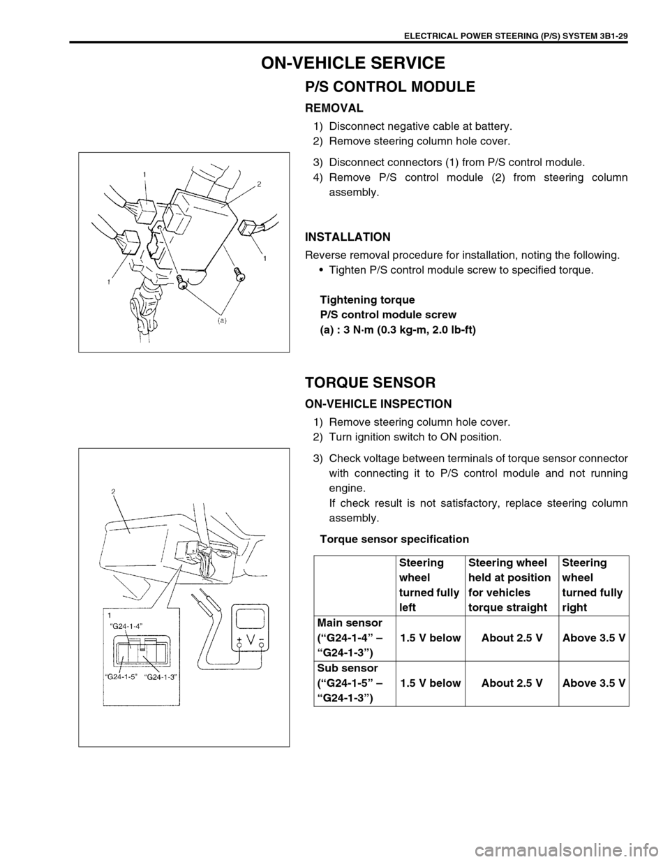
3) Disconnect connectors (1) from P/S control module.
4) Remove P/S control module (2) from steering column
assembly.
INSTALLATION
Reverse removal procedure for installation, noting the following.
Tighten P/S control module screw to specified torque.
Tightening torque
P/S control module screw
(a) : 3 N·m (0.3 kg-m, 2.0 lb-ft)
TORQUE SENSOR
ON-VEHICLE INSPECTION
1) Remove steering column hole cover.
2) Turn ignition switch to ON position.
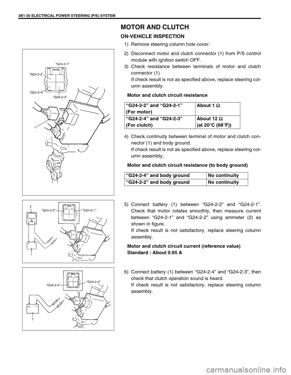
3) Check voltage between terminals of torque sensor connector
with connecting it to P/S control module and not running
engine.
If check result is not satisfactory, replace steering column
assembly.
Torque sensor specification
Steering
wheel
turned fully
leftSteering wheel
held at position
for vehicles
torque straightSteering
wheel
turned fully
right
Main sensor
(“G24-1-4” –
“G24-1-3”)1.5 V below About 2.5 V Above 3.5 V
Sub sensor
(“G24-1-5” –
“G24-1-3”)1.5 V below About 2.5 V Above 3.5 V
Page 171 of 698

3B1-30 ELECTRICAL POWER STEERING (P/S) SYSTEM
MOTOR AND CLUTCH
ON-VEHICLE INSPECTION
1) Remove steering column hole cover.
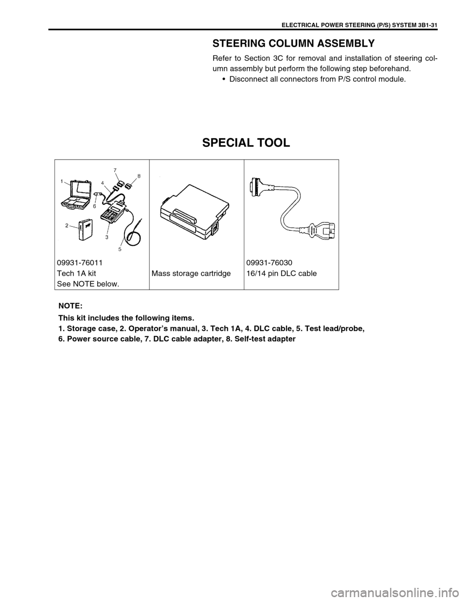
2) Disconnect motor and clutch connector (1) from P/S control
module with ignition switch OFF.
3) Check resistance between terminals of motor and clutch
connector (1)
If check result is not as specified above, replace steering col-
umn assembly.
Motor and clutch circuit resistance
4) Check continuity between terminal of motor and clutch con-
nector (1) and body ground.
If check result is not as specified above, replace steering col-
umn assembly.
Motor and clutch circuit resistance (to body ground)
5) Connect battery (1) between “G24-2-2” and “G24-2-1”.
Check that motor rotates smoothly, then measure current
between “G24-2-1” and “G24-2-2” using ammeter (2) as
shown in figure.
If check result is not satisfactory, replace steering column
assembly.
Motor and clutch circuit current (reference value)
Standard : About 0.65 A
6) Connect battery (1) between “G24-2-4” and “G24-2-3”, then
check that clutch operation sound is heard.
If check result is not satisfactory, replace steering column
assembly. “G24-2-2” and “G24-2-1”
(For motor)About 1
Ω
ΩΩ Ω
“G24-2-4” and “G24-2-3”
(For clutch)About 12
Ω
ΩΩ Ω
(at 20°C (68°F))
“G24-2-4” and body ground No continuity
“G24-2-2” and body ground No continuity
Page 172 of 698

ELECTRICAL POWER STEERING (P/S) SYSTEM 3B1-31
STEERING COLUMN ASSEMBLY
Refer to Section 3C for removal and installation of steering col-
umn assembly but perform the following step beforehand.
Disconnect all connectors from P/S control module.
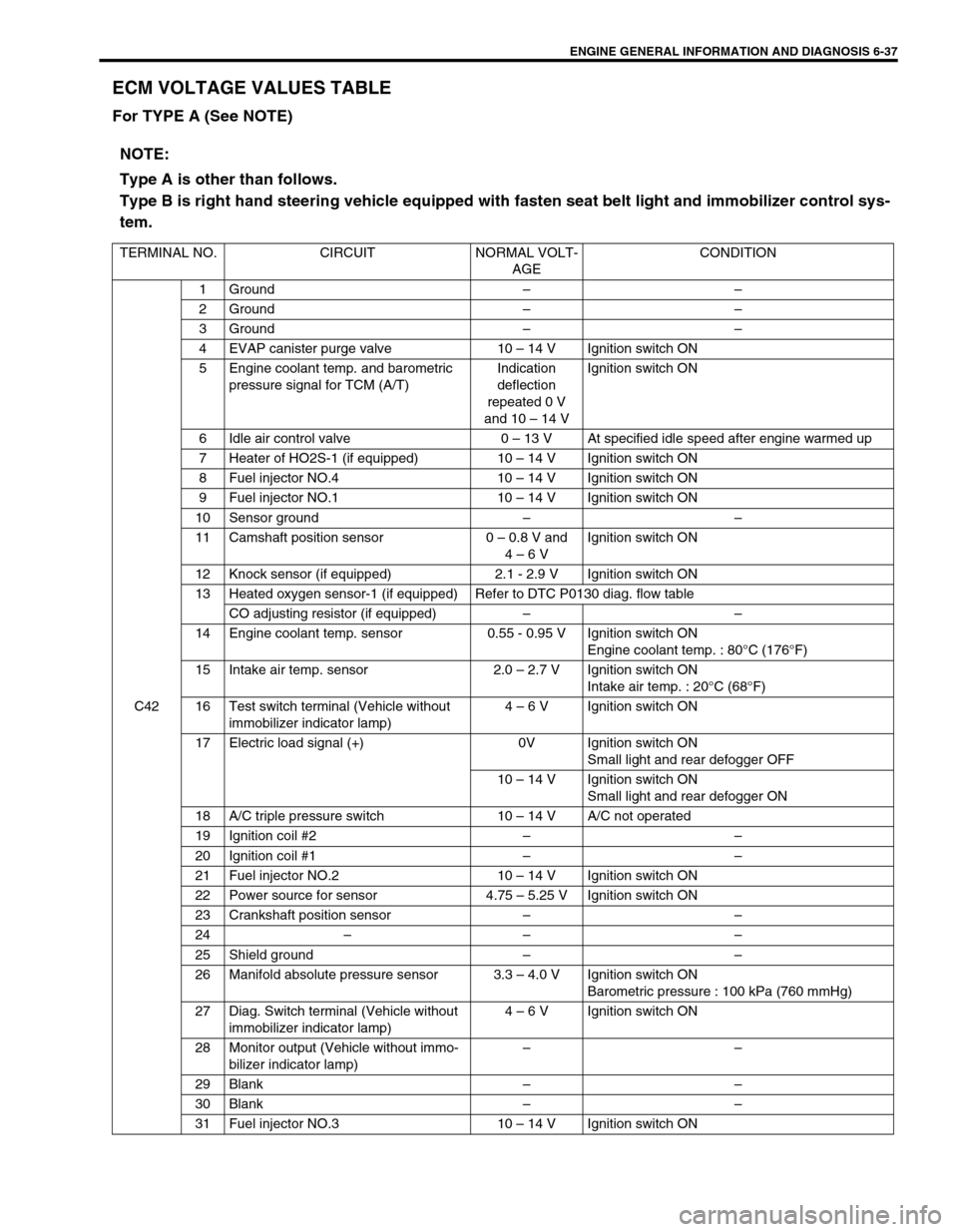
SPECIAL TOOL
09931-76011 09931-76030
Tech 1A kit
See NOTE below.Mass storage cartridge 16/14 pin DLC cable
NOTE:
This kit includes the following items.
1. Storage case, 2. Operator’s manual, 3. Tech 1A, 4. DLC cable, 5. Test lead/probe,
6. Power source cable, 7. DLC cable adapter, 8. Self-test adapter
Page 173 of 698

3B1-32 ELECTRICAL POWER STEERING (P/S) SYSTEM
Page 406 of 698

ENGINE GENERAL INFORMATION AND DIAGNOSIS 6-37
ECM VOLTAGE VALUES TABLE
For TYPE A (See NOTE)
NOTE:
Type A is other than follows.
Type B is right hand steering vehicle equipped with fasten seat belt light and immobilizer control sys-
tem.
TERMINAL NO. CIRCUIT NORMAL VOLT-
AGECONDITION
C421 Ground––
2 Ground––
3 Ground––
4 EVAP canister purge valve 10 – 14 V Ignition switch ON
5 Engine coolant temp. and barometric
pressure signal for TCM (A/T)Indication
deflection
repeated 0 V
and 10 – 14 VIgnition switch ON
6 Idle air control valve 0 – 13 V At specified idle speed after engine warmed up
7 Heater of HO2S-1 (if equipped) 10 – 14 V Ignition switch ON
8 Fuel injector NO.4 10 – 14 V Ignition switch ON
9 Fuel injector NO.1 10 – 14 V Ignition switch ON
10 Sensor ground––
11 Camshaft position sensor 0 – 0.8 V and
4 – 6 VIgnition switch ON
12 Knock sensor (if equipped) 2.1 - 2.9 V Ignition switch ON
13 Heated oxygen sensor-1 (if equipped) Refer to DTC P0130 diag. flow table
CO adjusting resistor (if equipped)––
14 Engine coolant temp. sensor 0.55 - 0.95 V Ignition switch ON
Engine coolant temp. : 80°C (176°F)
15 Intake air temp. sensor 2.0 – 2.7 V Ignition switch ON
Intake air temp. : 20°C (68°F)
16 Test switch terminal (Vehicle without
immobilizer indicator lamp)4 – 6 V Ignition switch ON
17 Electric load signal (+) 0V Ignition switch ON
Small light and rear defogger OFF
10 – 14 V Ignition switch ON
Small light and rear defogger ON
18 A/C triple pressure switch 10 – 14 V A/C not operated
19 Ignition coil #2––
20 Ignition coil #1––
21 Fuel injector NO.2 10 – 14 V Ignition switch ON
22 Power source for sensor 4.75 – 5.25 V Ignition switch ON
23 Crankshaft position sensor––
24–– –
25 Shield ground––
26 Manifold absolute pressure sensor 3.3 – 4.0 V Ignition switch ON
Barometric pressure : 100 kPa (760 mmHg)
27 Diag. Switch terminal (Vehicle without
immobilizer indicator lamp)4 – 6 V Ignition switch ON
28 Monitor output (Vehicle without immo-
bilizer indicator lamp)––
29 Blank––
30 Blank––
31 Fuel injector NO.3 10 – 14 V Ignition switch ON