SUZUKI SWIFT 2000 1.G RG413 Service Repair Manual
Manufacturer: SUZUKI, Model Year: 2000, Model line: SWIFT, Model: SUZUKI SWIFT 2000 1.GPages: 698, PDF Size: 16.01 MB
Page 51 of 698

0B-22 MAINTENANCE AND LUBRICATION
Page 52 of 698
HEATER AND VENTILATION 1A-1
6F1
6F2
6G
1A
6K
7A
7A1
7B1
7C1
7D
7E
7F
8A
8B
8C
8D
8E
9
10
10A
10B
SECTION 1A
HEATER AND VENTILATION
CONTENTS
GENERAL DESCRIPTION .............................. 1A-2
DIAGNOSIS ..................................................... 1A-3
DIAGNOSIS TABLE ..................................... 1A-3
WIRING CIRCUIT ........................................ 1A-4
ON-VEHICLE SERVICE .................................. 1A-5
HEATER UNIT ............................................. 1A-5BLOWER FAN MOTOR ............................... 1A-7
BLOWER FAN MOTOR RESISTOR ........... 1A-8
HEATER CONTROL ASSEMBLY ............... 1A-9
AIR INLET BOX ......................................... 1A-12
VENTILATION LOUVER............................ 1A-13
REQUIRED SERVICE MATERIALS ............. 1A-14
WARNING:
For vehicles equipped with Supplement Restraint (Air Bag) System
Service on and around the air bag system components or wiring must be performed only by an
authorized SUZUKI dealer. Refer to “Air Bag System Components and Wiring Location View” under
“General Description” in Section 10B in order to confirm whether you are performing service on or
near the air bag system components or wiring. Please observe all WARNINGS and “Service Precau-
tions” under “On-Vehicle Service” in Section 10B before performing service on or around the air
bag system components or wiring. Failure to follow WARNINGS could result in unintentional activa-
tion of the system or could render the system inoperative. Either or these two conditions may result
in severe injury.
Technical service work must be started at least 90 seconds after the ignition switch is turned to the
“LOCK” position and the negative cable is disconnected from the battery. Otherwise, the system
may be activated by reserve energy in the Sensing and Diagnostic Module (SDM).
NOTE:
The link mechanism of the heater varies depending on the specifications.
Page 53 of 698
1A-2 HEATER AND VENTILATION
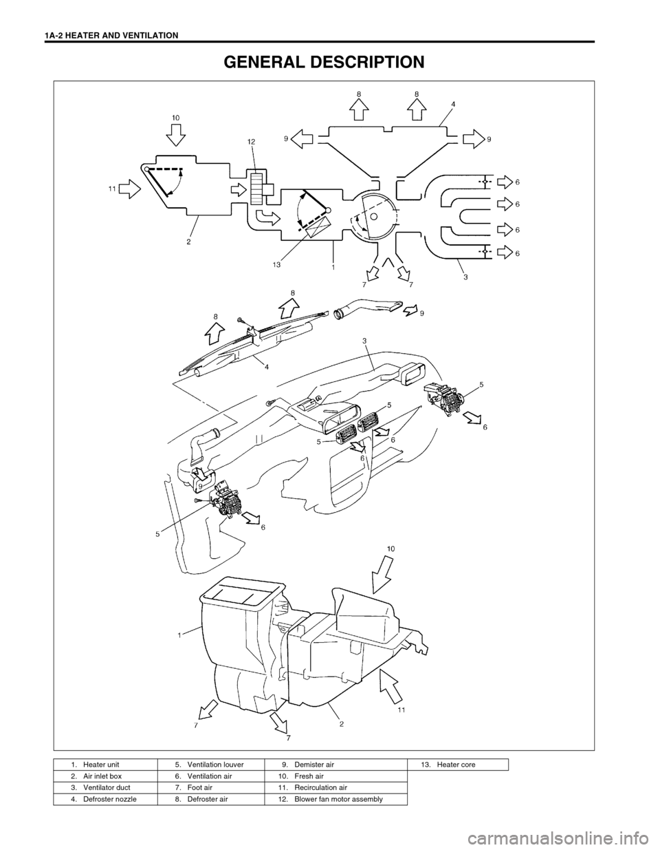
GENERAL DESCRIPTION
1. Heater unit 5. Ventilation louver 9. Demister air 13. Heater core
2. Air inlet box 6. Ventilation air 10. Fresh air
3. Ventilator duct 7. Foot air 11. Recirculation air
4. Defroster nozzle 8. Defroster air 12. Blower fan motor assembly
Page 54 of 698
HEATER AND VENTILATION 1A-3
DIAGNOSIS
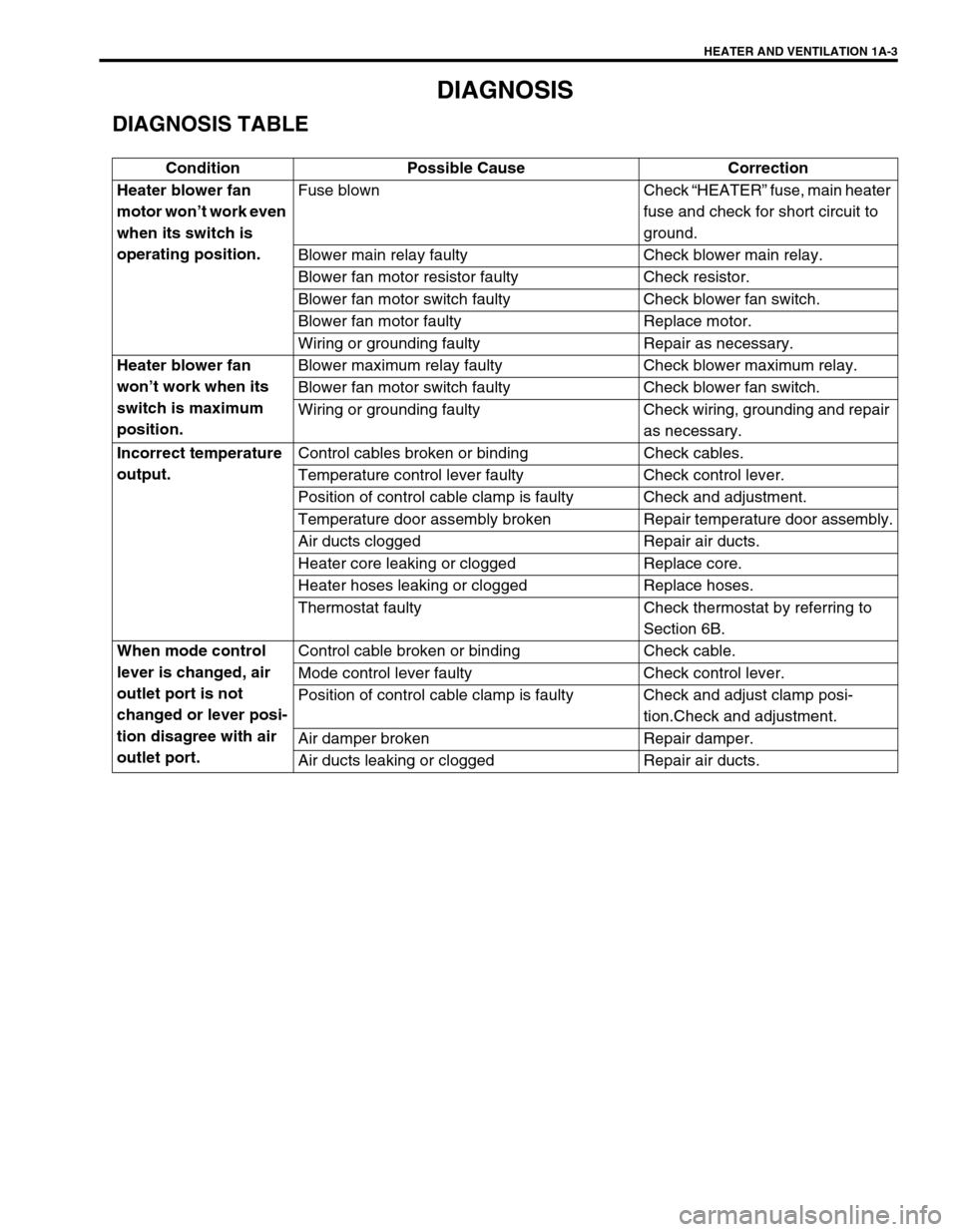
DIAGNOSIS TABLE
Condition Possible Cause Correction
Heater blower fan
motor won’t work even
when its switch is
operating position.Fuse blown Check “HEATER” fuse, main heater
fuse and check for short circuit to
ground.
Blower main relay faulty Check blower main relay.
Blower fan motor resistor faulty Check resistor.
Blower fan motor switch faulty Check blower fan switch.
Blower fan motor faulty Replace motor.
Wiring or grounding faulty Repair as necessary.
Heater blower fan
won’t work when its
switch is maximum
position.Blower maximum relay faulty Check blower maximum relay.
Blower fan motor switch faulty Check blower fan switch.
Wiring or grounding faulty Check wiring, grounding and repair
as necessary.
Incorrect temperature
output.Control cables broken or binding Check cables.
Temperature control lever faulty Check control lever.
Position of control cable clamp is faulty Check and adjustment.
Temperature door assembly broken Repair temperature door assembly.
Air ducts clogged Repair air ducts.
Heater core leaking or clogged Replace core.
Heater hoses leaking or clogged Replace hoses.
Thermostat faulty Check thermostat by referring to
Section 6B.
When mode control
lever is changed, air
outlet port is not
changed or lever posi-
tion disagree with air
outlet port.Control cable broken or binding Check cable.
Mode control lever faulty Check control lever.
Position of control cable clamp is faulty Check and adjust clamp posi-
tion.Check and adjustment.
Air damper broken Repair damper.
Air ducts leaking or clogged Repair air ducts.
Page 55 of 698
1A-4 HEATER AND VENTILATION
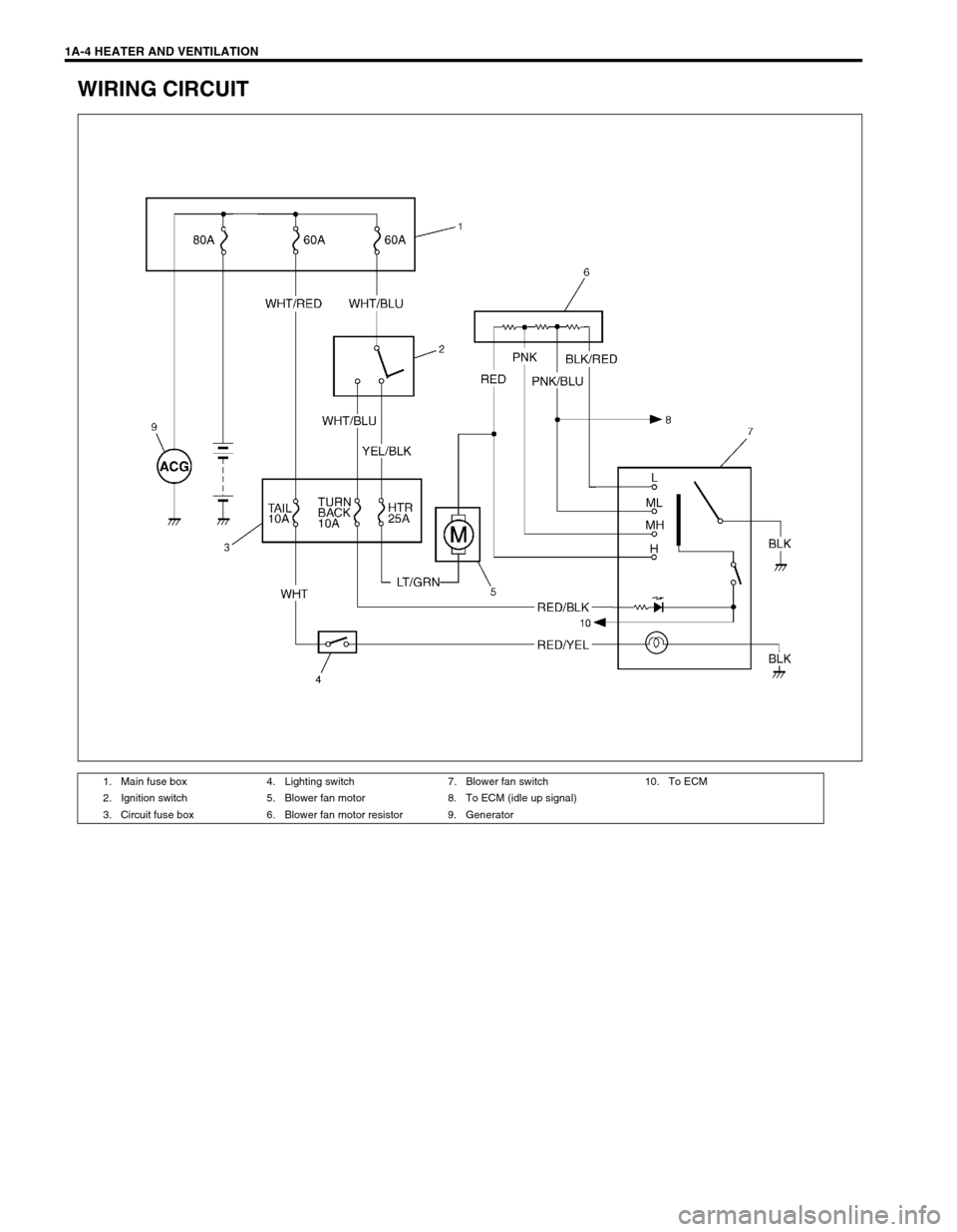
WIRING CIRCUIT
1. Main fuse box 4. Lighting switch 7. Blower fan switch 10. To ECM
2. Ignition switch 5. Blower fan motor 8. To ECM (idle up signal)
3. Circuit fuse box 6. Blower fan motor resistor 9. Generator
Page 56 of 698
HEATER AND VENTILATION 1A-5
ON-VEHICLE SERVICE
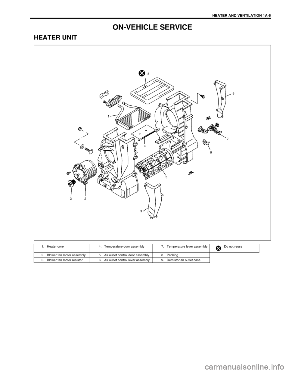
HEATER UNIT
1. Heater core 4. Temperature door assembly 7. Temperature lever assembly Do not reuse
2. Blower fan motor assembly 5. Air outlet control door assembly 8. Packing
3. Blower fan motor resistor 6. Air outlet control lever assembly 9. Demistor air outlet case
Page 57 of 698
1A-6 HEATER AND VENTILATION
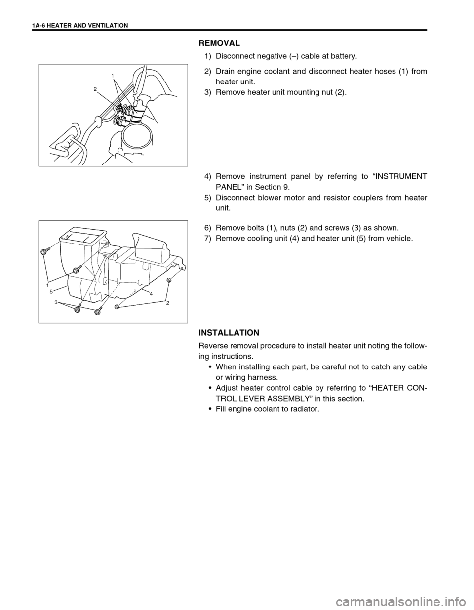
REMOVAL
1) Disconnect negative (–) cable at battery.
2) Drain engine coolant and disconnect heater hoses (1) from
heater unit.
3) Remove heater unit mounting nut (2).
4) Remove instrument panel by referring to “INSTRUMENT
PANEL” in Section 9.
5) Disconnect blower motor and resistor couplers from heater
unit.
6) Remove bolts (1), nuts (2) and screws (3) as shown.
7) Remove cooling unit (4) and heater unit (5) from vehicle.
INSTALLATION
Reverse removal procedure to install heater unit noting the follow-
ing instructions.
When installing each part, be careful not to catch any cable
or wiring harness.
Adjust heater control cable by referring to “HEATER CON-
TROL LEVER ASSEMBLY” in this section.
Fill engine coolant to radiator.
Page 58 of 698
HEATER AND VENTILATION 1A-7
BLOWER FAN MOTOR
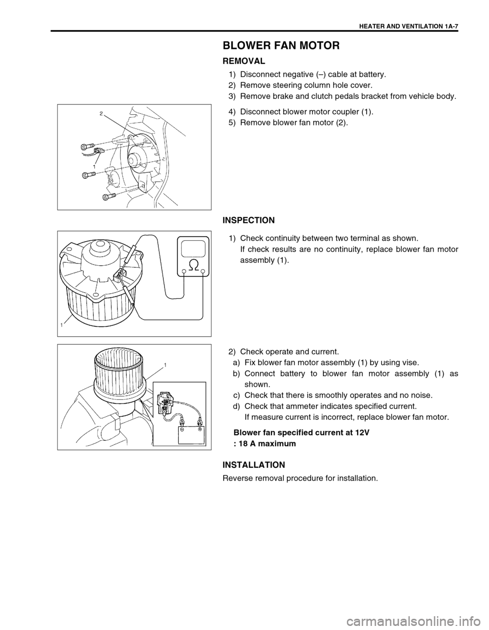
REMOVAL
1) Disconnect negative (–) cable at battery.
2) Remove steering column hole cover.
3) Remove brake and clutch pedals bracket from vehicle body.
4) Disconnect blower motor coupler (1).
5) Remove blower fan motor (2).
INSPECTION
1) Check continuity between two terminal as shown.
If check results are no continuity, replace blower fan motor
assembly (1).
2) Check operate and current.
a) Fix blower fan motor assembly (1) by using vise.
b) Connect battery to blower fan motor assembly (1) as
shown.
c) Check that there is smoothly operates and no noise.
d) Check that ammeter indicates specified current.
If measure current is incorrect, replace blower fan motor.
Blower fan specified current at 12V
: 18 A maximum
INSTALLATION
Reverse removal procedure for installation.
Page 59 of 698
1A-8 HEATER AND VENTILATION
BLOWER FAN MOTOR RESISTOR
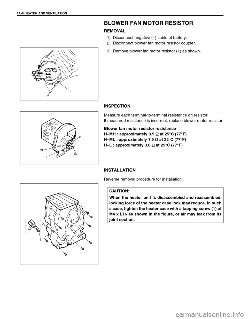
REMOVAL
1) Disconnect negative (–) cable at battery.
2) Disconnect blower fan motor resistor coupler.
3) Remove blower fan motor resistor (1) as shown.
INSPECTION
Measure each terminal-to-terminal resistance on resistor
If measured resistance is incorrect, replace blower motor resistor.
Blower fan motor resistor resistance
H–MH : approximately 0.5
Ω
ΩΩ Ω at 25°C (77°F)
H–ML : approximately 1.5
Ω
ΩΩ Ω at 25°C (77°F)
H–L : approximately 3.0
Ω
ΩΩ Ω at 25°C (77°F)
INSTALLATION
Reverse removal procedure for installation.
CAUTION:
When the heater unit is disassembled and reassembled,
locking force of the heater case lock may reduce. In such
a case, tighten the heater case with a tapping screw (1) of
M4 x L16 as shown in the figure, or air may leak from its
joint section.
1
Page 60 of 698
HEATER AND VENTILATION 1A-9
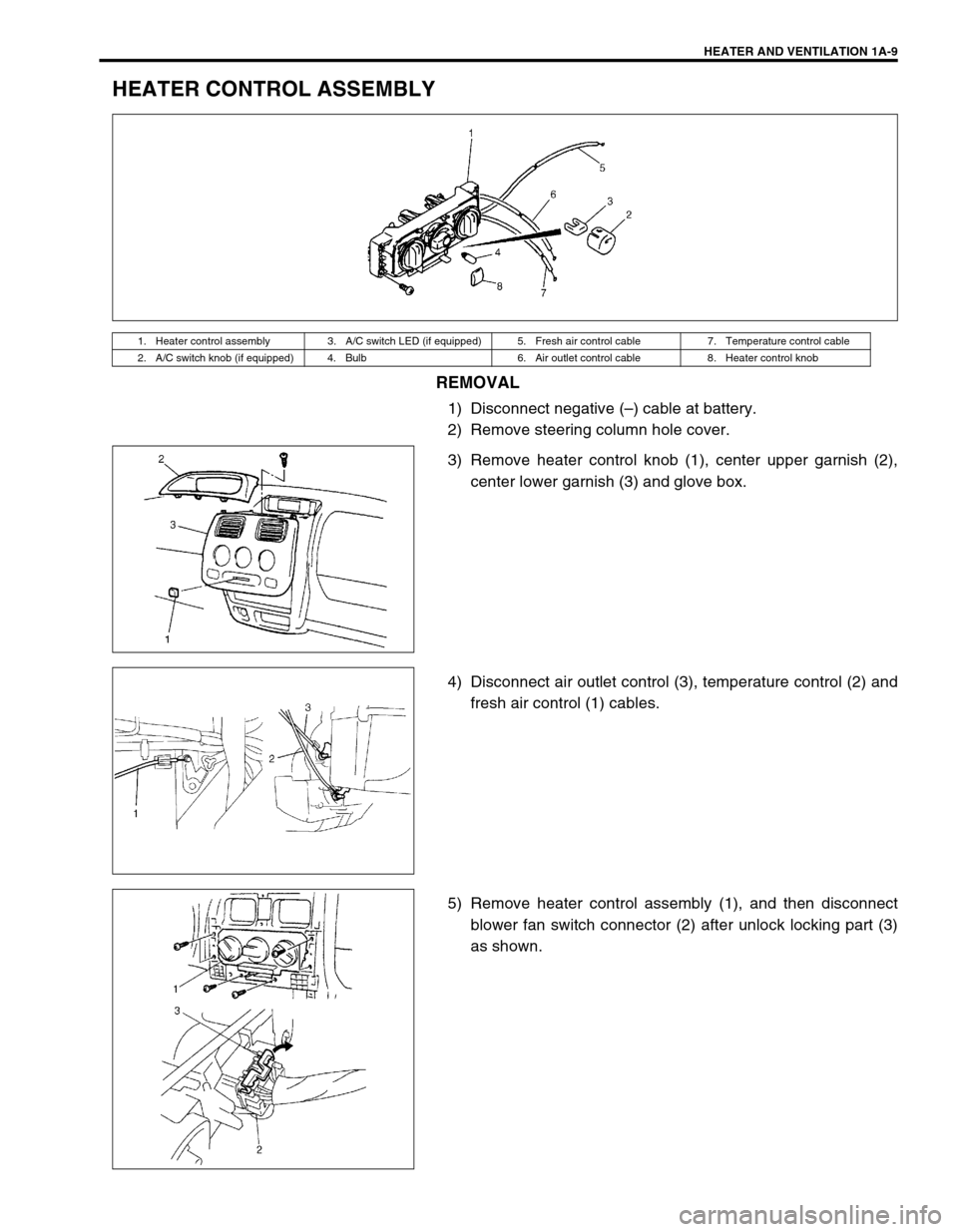
HEATER CONTROL ASSEMBLY
REMOVAL
1) Disconnect negative (–) cable at battery.
2) Remove steering column hole cover.
3) Remove heater control knob (1), center upper garnish (2),
center lower garnish (3) and glove box.
4) Disconnect air outlet control (3), temperature control (2) and
fresh air control (1) cables.
5) Remove heater control assembly (1), and then disconnect
blower fan switch connector (2) after unlock locking part (3)
as shown.
1. Heater control assembly 3. A/C switch LED (if equipped) 5. Fresh air control cable 7. Temperature control cable
2. A/C switch knob (if equipped) 4. Bulb 6. Air outlet control cable 8. Heater control knob