engine type SUZUKI SWIFT 2000 1.G RG413 Service Repair Manual
[x] Cancel search | Manufacturer: SUZUKI, Model Year: 2000, Model line: SWIFT, Model: SUZUKI SWIFT 2000 1.GPages: 698, PDF Size: 16.01 MB
Page 634 of 698
ENGINE AND EMISSION CONTROL SYSTEM 6E1-13
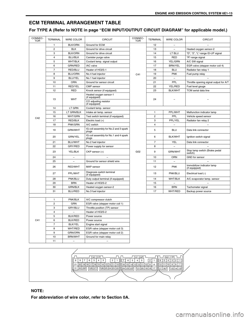
ECM TERMINAL ARRANGEMENT TABLE
For TYPE A (Refer to NOTE in page “ECM INPUT/OUTPUT CIRCUIT DIAGRAM” for applicable model.)
CONNEC-
TORTERMINAL WIRE COLOR CIRCUITCONNEC-
TORTERMINAL WIRE COLOR CIRCUIT
C421 BLK/ORN Ground for ECM
C4112––
2 BLK Ground for drive circuit 13–Heated oxygen sensor-2
3 BLK/ORN Ground for drive circuit 14 LT BLU“D”, “2”, “L”-range ID-UP signal
4 BLU/BLK Canister purge valve 15 RED“R”-range signal
5 WHT/BLK Coolant temp. signal output 16 YEL/GRN A/C SW signal
6 GRN/RED IAC valve 17 BRN/YEL EGR valve (stepper motor coil 4)
7 RED/BLU Heater of HO2S-1 18 BLU Radiator fan relay 1
8 BLU/ORN No.4 fuel injector 19 PNK Fuel pump relay
9 BLU/YEL No.1 fuel injector 20––
10 ORN Ground for sensor circuit 21 PPL Throttle opening signal output for A/T
11 RED/YEL CMP sensor 22 YEL/RED Fuel level gauge
12 RED Knock sensor (if equipped) 23 BLK/WHT TCM serial data line
13 WHTHeated oxygen sensor-1
(if equipped)
24––
CO adjusting resistor
(if equipped)
14 LT GRN Coolant temp. sensor
15 LT GRN/BLK Intake air temp. sensor
G021 PPL/WHT Malfunction indicator lamp
16 WHT/GRN Test switch terminal (if equipped) 2 PPL Vehicle speed sensor
17 RED/BLK Electric load (+) 3 PPL/YEL Radiator fan relay 2
18 PNK/GRN A/C switch 4––
19 GRN/WHTIG coil assembly for No.2 and 3 spark
plugs5 BLU Data link connector
20 GRN/YELIG coil assembly for No.1 and 4 spark
plugs6 BLK/WHT Ignition switch signal
21 BLU/WHT No.2 fuel injector 7 YEL Data link connector
22 GRY/RED Power supply for sensor 8––
23 YEL/BLK CKP sensor (+) 9 GRN/WHTStop lamp switch (Brake pedal
switch)
24––10 ORN GND for sensor
25–Ground for sensor shield wire 11––
26 RED/WHT MAP sensor 12 PNKImmobilizer indicator lamp
(if equipped)
27 PPL/WHTDiagnosis switch terminal
(if equipped)13 PNK/BLU Electrical load (-)
28 PNK/BLU Duty output terminal (if equipped) 14 WHT/BLK A/C evaporator temp. sensor
29 BRN Heater of HO2S-2 15––
30 GRN/BLK Heated oxygen sensor-2 16 BRN Tachometer signal
31 BLU/RED No.3 fuel injector 17 WHT/RED Backup power source
C411 PNK/BLK A/C compressor clutch
2 GRN EGR valve (stepper motor coil 1)
3 GRY/BLU Throttle position (TP) sensor
4–Heater of HO2S-2
5 BLK/RED Power source
6 BLK/RED Power source
7 BLK/YEL Engine start signal
8 WHT/RED EGR valve (stepper motor coil 3)
9 GRN/ORN EGR valve (stepper motor coil 2)
10 BRN/WHT Ground for main relay
11––
C42 (31P) C41 (24P) G02 (17P)1 2 3 4 5 6 7 8 9
10 11 12 13 14 15 16 17 18 19 20 21
22 23 24 25 26 28 27 29 30 315 6
1 2 3 4 5 6 7
11 12
9 10 11 13 12 14 15 16
16 171 2
7 8
13 14 3 4
9 10
15 17 188
19 20 21 22 23 24
NOTE:
For abbreviation of wire color, refer to Section 0A.
Page 635 of 698
6E1-14 ENGINE AND EMISSION CONTROL SYSTEM
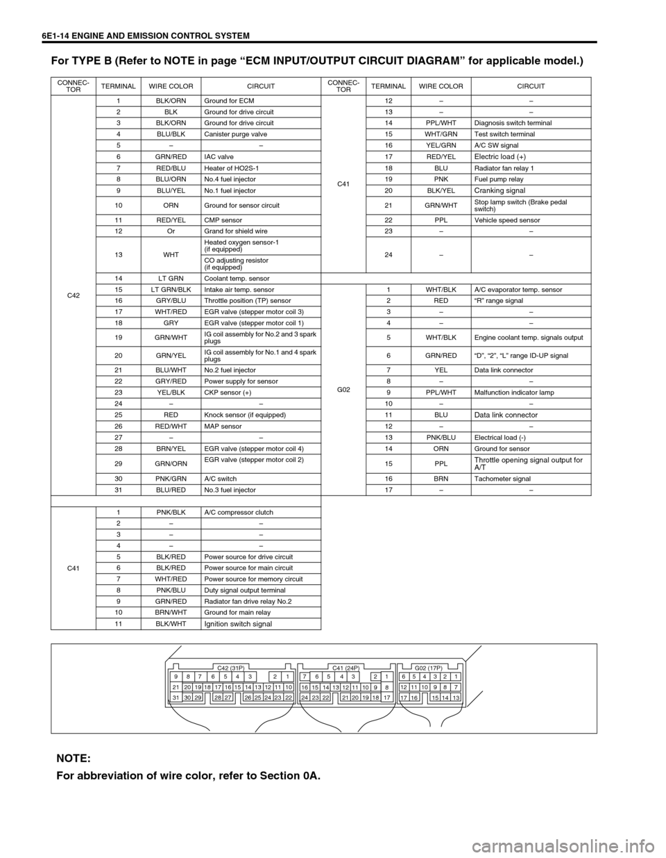
For TYPE B (Refer to NOTE in page “ECM INPUT/OUTPUT CIRCUIT DIAGRAM” for applicable model.)
CONNEC-
TORTERMINAL WIRE COLOR CIRCUITCONNEC-
TORTERMINAL WIRE COLOR CIRCUIT
C421 BLK/ORN Ground for ECM
C4112––
2 BLK Ground for drive circuit 13––
3 BLK/ORN Ground for drive circuit 14 PPL/WHT Diagnosis switch terminal
4 BLU/BLK Canister purge valve 15 WHT/GRN Test switch terminal
5––16 YEL/GRN A/C SW signal
6 GRN/RED IAC valve 17 RED/YEL
Electric load (+)
7 RED/BLU Heater of HO2S-1 18 BLU Radiator fan relay 1
8 BLU/ORN No.4 fuel injector 19 PNK Fuel pump relay
9 BLU/YEL No.1 fuel injector 20 BLK/YEL
Cranking signal
10 ORN Ground for sensor circuit 21 GRN/WHTStop lamp switch (Brake pedal
switch)
11 RED/YEL CMP sensor 22 PPL Vehicle speed sensor
12 Or Grand for shield wire 23––
13 WHTHeated oxygen sensor-1
(if equipped)
24––
CO adjusting resistor
(if equipped)
14 LT GRN Coolant temp. sensor
15 LT GRN/BLK Intake air temp. sensor
G021 WHT/BLK A/C evaporator temp. sensor
16 GRY/BLU Throttle position (TP) sensor 2 RED“R” range signal
17 WHT/RED EGR valve (stepper motor coil 3) 3––
18 GRY EGR valve (stepper motor coil 1) 4––
19 GRN/WHTIG coil assembly for No.2 and 3 spark
plugs5 WHT/BLK Engine coolant temp. signals output
20 GRN/YELIG coil assembly for No.1 and 4 spark
plugs6 GRN/RED“D”, “2”, “L” range ID-UP signal
21 BLU/WHT No.2 fuel injector 7 YEL Data link connector
22 GRY/RED Power supply for sensor 8––
23 YEL/BLK CKP sensor (+) 9 PPL/WHT Malfunction indicator lamp
24––10––
25 RED Knock sensor (if equipped) 11 BLU
Data link connector
26 RED/WHT MAP sensor 12––
27––13 PNK/BLU Electrical load (-)
28 BRN/YEL EGR valve (stepper motor coil 4) 14 ORN Ground for sensor
29 GRN/ORNEGR valve (stepper motor coil 2)
15 PPL
Throttle opening signal output for
A/T
30 PNK/GRN A/C switch 16 BRN Tachometer signal
31 BLU/RED No.3 fuel injector 17––
C411 PNK/BLK A/C compressor clutch
2––
3––
4––
5 BLK/RED Power source for drive circuit
6 BLK/RED Power source for main circuit
7 WHT/RED Power source for memory circuit
8 PNK/BLU Duty signal output terminal
9 GRN/RED Radiator fan drive relay No.2
10 BRN/WHT Ground for main relay
11 BLK/WHT
Ignition switch signal
C42 (31P) C41 (24P) G02 (17P)1 2 3 4 5 6 7 8 9
10 11 12 13 14 15 16 17 18 19 20 21
22 23 24 25 26 28 27 29 30 315 6
1 2 3 4 5 6 7
11 12
9 10 11 13 12 14 15 16
16 171 2
7 8
13 14 3 4
9 10
15 17 188
19 20 21 22 23 24
NOTE:
For abbreviation of wire color, refer to Section 0A.
Page 666 of 698

6F1-4 IGNITION SYSTEM (ELECTRONIC IGNITION SYSTEM)
IGNITION SYSTEM DIAGNOSTIC FLOW TABLE
Step Action Yes No
1Was “ENGINE DIAG. FLOW TABLE” in Section 6 per-
formed?Go to Step 2. Go to “ENGINE DIAG.
FLOW TABLE” in Sec-
tion 6.
2Ignition Spark Test
1) Check all spark plugs for condition and type refer-
ring to “Spark Plugs” section.
2) If OK, perform ignition spark test, referring to “Igni-
tion Spark Test” in this section.
Is spark emitted from all spark plugs?Go to Step 11. Go to Step 3.
3Diagnostic Trouble Code (DTC) Check Is DTC stored
in ECM?Go to applicable DTC
Diag. Flow Table in
Section 6.Go to Step 4.
4Electrical Connection Check
1) Check ignition coil assemblies and high-tension
cords for electrical connection.
Are they connected securely?Go to Step 5. Connect securely.
5High-tension Cords Check
1) Check high-tension cord for resistance referring to
“High-Tension Cords” in this section.
Is check result satisfactory?Go to Step 6. Replace high-tension
cord(s).
6Ignition Coil Assembly Power Supply and Ground Cir-
cuit Check
1) Check ignition coil assembly power supply and
ground circuits for open and short.
Are circuits in good condition?Go to Step 7. Repair or replace.
7Ignition Coil Assembly Check
1) Check ignition coil for resistance referring to “Igni-
tion Coil Assembly” in this section.
Is check result satisfactory?Go to Step 8. Replace ignition coil
assembly.
8Crankshaft Position (CKP) Sensor Check
1) Check crankshaft position sensor referring to Step
3 and 4 of “DTC P0335 (No.23) Diag. Flow Table”
in Section 6.
Is check result satisfactory?Go to Step 9. Tighten CKP sensor
bolt, replace CKP sen-
sor or CKP sensor
plate.
9Ignition Trigger Signal Circuit Check
1) Check ignition trigger signal wire for open, short
and poor connection.
Is circuit in good condition?Go to Step 10. Repair or replace.
10A Known-good Ignition Coil Assembly Substitution
1) Substitute a known-good ignition coil assembly
and then repeat Step 2.
Is check result of Step 2 satisfactory?Go to Step 11. Substitute a known-
good ECM and then
repeat Step 2.
11Ignition Timing Check
1) Check initial ignition timing and ignition timing
advance referring to “Ignition Timing” in this sec-
tion.
Is check result satisfactory?System is in good con-
dition.Check CKP sensor,
CKP sensor plate and
input signals related to
this system.
Page 667 of 698
IGNITION SYSTEM (ELECTRONIC IGNITION SYSTEM 6F1-5
ON-VEHICLE SERVICE
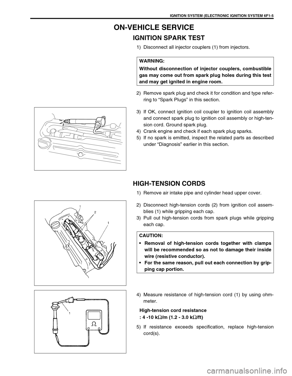
IGNITION SPARK TEST
1) Disconnect all injector couplers (1) from injectors.
2) Remove spark plug and check it for condition and type refer-
ring to “Spark Plugs” in this section.
3) If OK, connect ignition coil coupler to ignition coil assembly
and connect spark plug to ignition coil assembly or high-ten-
sion cord. Ground spark plug.
4) Crank engine and check if each spark plug sparks.
5) If no spark is emitted, inspect the related parts as described
under “Diagnosis” earlier in this section.
HIGH-TENSION CORDS
1) Remove air intake pipe and cylinder head upper cover.
2) Disconnect high-tension cords (2) from ignition coil assem-
blies (1) while gripping each cap.
3) Pull out high-tension cords from spark plugs while gripping
each cap.
4) Measure resistance of high-tension cord (1) by using ohm-
meter.
High-tension cord resistance
: 4 -10 k
Ω/m (1.2 - 3.0 kΩ/ft)
5) If resistance exceeds specification, replace high-tension
cord(s). WARNING:
Without disconnection of injector couplers, combustible
gas may come out from spark plug holes during this test
and may get ignited in engine room.
CAUTION:
Removal of high-tension cords together with clamps
will be recommended so as not to damage their inside
wire (resistive conductor).
For the same reason, pull out each connection by grip-
ping cap portion.
Page 668 of 698
6F1-6 IGNITION SYSTEM (ELECTRONIC IGNITION SYSTEM)
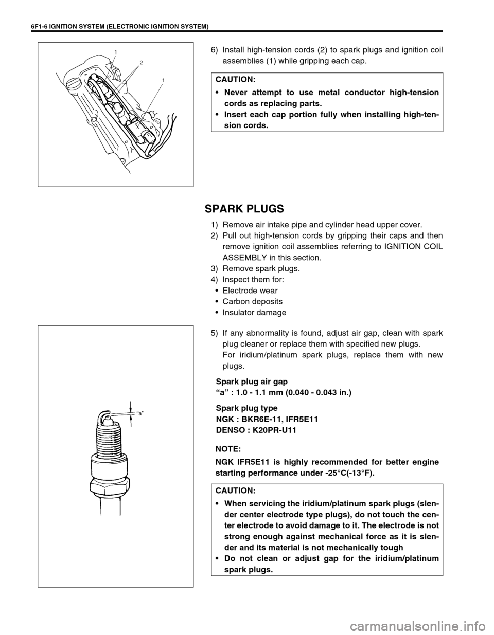
6) Install high-tension cords (2) to spark plugs and ignition coil
assemblies (1) while gripping each cap.
SPARK PLUGS
1) Remove air intake pipe and cylinder head upper cover.
2) Pull out high-tension cords by gripping their caps and then
remove ignition coil assemblies referring to IGNITION COIL
ASSEMBLY in this section.
3) Remove spark plugs.
4) Inspect them for:
Electrode wear
Carbon deposits
Insulator damage
5) If any abnormality is found, adjust air gap, clean with spark
plug cleaner or replace them with specified new plugs.
For iridium/platinum spark plugs, replace them with new
plugs.
Spark plug air gap
“a” : 1.0 - 1.1 mm (0.040 - 0.043 in.)
Spark plug type
NGK : BKR6E-11, IFR5E11
DENSO : K20PR-U11 CAUTION:
Never attempt to use metal conductor high-tension
cords as replacing parts.
Insert each cap portion fully when installing high-ten-
sion cords.
NOTE:
NGK IFR5E11 is highly recommended for better engine
starting performance under -25°C(-13°F).
CAUTION:
When servicing the iridium/platinum spark plugs (slen-
der center electrode type plugs), do not touch the cen-
ter electrode to avoid damage to it. The electrode is not
strong enough against mechanical force as it is slen-
der and its material is not mechanically tough
Do not clean or adjust gap for the iridium/platinum
spark plugs.
Page 682 of 698
6H-2 CHARGING SYSTEM
GENERAL DESCRIPTION
BATTERY
The battery has three major functions in the electrical system.
It is a source of electrical energy for cranking the engine.
It acts as a voltage stabilizer for the electrical system.
It can, for a limited time, provide energy when the electrical load exceeds the output of the generator.
CARRIER AND HOLD-DOWN
The battery carrier should be in good condition so that it will support the battery securely and keep it level.
Before installing the battery, the battery carrier and hold-down clamp should be clean and free from corrosion
and make certain there are no parts in carrier.
To prevent the battery from shaking in its carrier, the hold-down bolts should be tight enough but not over-tight-
ened.
ELECTROLYTE FREEZING
The freezing point of electrolyte depends on its specific gravity. Since freezing may ruin a battery, it should be
protected against freezing by keeping it in a fully charged condition. If a battery is frozen accidentally, it should
not be charged until it is warmed.
SULFATION
If the battery is allowed to stand for a long period in discharged condition, the lead sulfate becomes converted
into a hard, crystalline substance, which will not easily turn back to the active material again during the subse-
quent recharging. “Sulfation” means the result as well as the process of that reaction. Such a battery can be
revived by very slow charging and may be restored to usable condition but its capacity is lower than before.
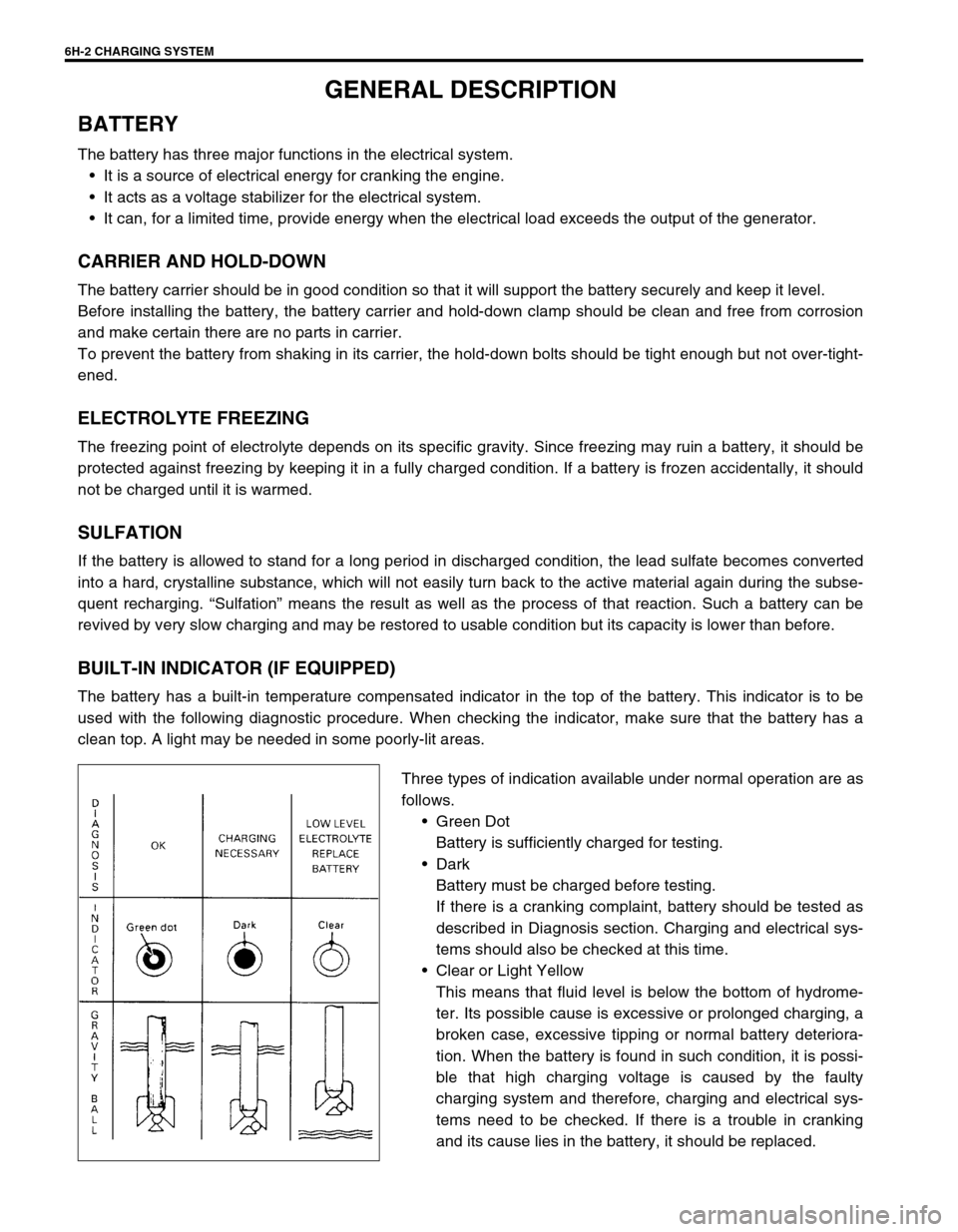
BUILT-IN INDICATOR (IF EQUIPPED)
The battery has a built-in temperature compensated indicator in the top of the battery. This indicator is to be
used with the following diagnostic procedure. When checking the indicator, make sure that the battery has a
clean top. A light may be needed in some poorly-lit areas.
Three types of indication available under normal operation are as
follows.
Green Dot
Battery is sufficiently charged for testing.
Dark
Battery must be charged before testing.
If there is a cranking complaint, battery should be tested as
described in Diagnosis section. Charging and electrical sys-
tems should also be checked at this time.
Clear or Light Yellow
This means that fluid level is below the bottom of hydrome-
ter. Its possible cause is excessive or prolonged charging, a
broken case, excessive tipping or normal battery deteriora-
tion. When the battery is found in such condition, it is possi-
ble that high charging voltage is caused by the faulty
charging system and therefore, charging and electrical sys-
tems need to be checked. If there is a trouble in cranking
and its cause lies in the battery, it should be replaced.