engine type SUZUKI SWIFT 2000 1.G RG413 Service Service Manual
[x] Cancel search | Manufacturer: SUZUKI, Model Year: 2000, Model line: SWIFT, Model: SUZUKI SWIFT 2000 1.GPages: 698, PDF Size: 16.01 MB
Page 548 of 698
ENGINE MECHANICAL (M13 ENGINE) 6A1-47
DISASSEMBLY
1) For ease in servicing cylinder head, remove intake manifold,
injectors and exhaust manifold from cylinder head.
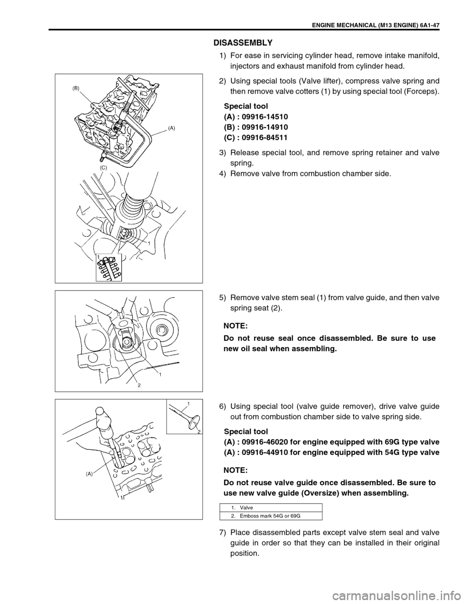
2) Using special tools (Valve lifter), compress valve spring and
then remove valve cotters (1) by using special tool (Forceps).
Special tool
(A) : 09916-14510
(B) : 09916-14910
(C) : 09916-84511
3) Release special tool, and remove spring retainer and valve
spring.
4) Remove valve from combustion chamber side.
5) Remove valve stem seal (1) from valve guide, and then valve
spring seat (2).
6) Using special tool (valve guide remover), drive valve guide
out from combustion chamber side to valve spring side.
Special tool
(A) : 09916-46020 for engine equipped with 69G type valve
(A) : 09916-44910 for engine equipped with 54G type valve
7) Place disassembled parts except valve stem seal and valve
guide in order so that they can be installed in their original
position.
NOTE:
Do not reuse seal once disassembled. Be sure to use
new oil seal when assembling.
NOTE:
Do not reuse valve guide once disassembled. Be sure to
use new valve guide (Oversize) when assembling.
1. Valve
2. Emboss mark 54G or 69G
Page 549 of 698

6A1-48 ENGINE MECHANICAL (M13 ENGINE)
INSPECTION
Valve Guides
Using a micrometer and bore gauge, take diameter readings on
valve stems and guides to check stem-to-guide clearance. Be
sure to take reading at more than one place along the length of
each stem and guide.
If clearance exceeds limit, replace valve and valve guide.
Valve stem-to-guide clearance
Valve stem diameter [A]
Valve guide bore [B] standard
In and Ex : 6.000 – 6.012 mm (0.2362 – 0.2367 in.) for 69G
type valve
In and Ex : 5.485 – 5.510 mm (0.2159 – 0.2169 in.) for 54G
type valve
If bore gauge is not available, check end deflection of valve stem
with a dial gauge instead.
Move stem end in directions (1) and (2) to measure end deflec-
tion.
If deflection exceeds its limit, replace valve stem and valve guide.
Valve stem end deflection limit
In : 0.14 mm (0.005 in.)
Ex : 0.18 mm (0.007 in.)Valve type Standard Limit
69GIn0.020 – 0.047 mm
(0.0008 – 0.0019 in.)0.07 mm
(0.0028 in.)
Ex0.045 – 0.072 mm
(0.0018 – 0.0028 in.)0.09 mm
(0.0035 in.)
54GIn0.020 – 0.030 mm
(0.0008 – 0.0012 in.)0.05 mm
(0.0017 in.)
Ex0.045 – 0.055 mm
(0.0018 – 0.0022 in.)0.07 mm
(0.0028 in.)
Valve type Standard
69GIn5.965 – 5.980 mm
(0.2348 – 0.2354 in.)
Ex5.940 – 5.955 mm
(0.2339 – 0.2344 in.)
54GIn5.465 – 5.480 mm
(0.2152 – 0.2157 in.)
Ex5.440 – 5.455 mm
(0.2142 – 0.2148 in.)
1. Emboss mark 54G or 69G
Page 553 of 698
6A1-52 ENGINE MECHANICAL (M13 ENGINE)
Valve Springs
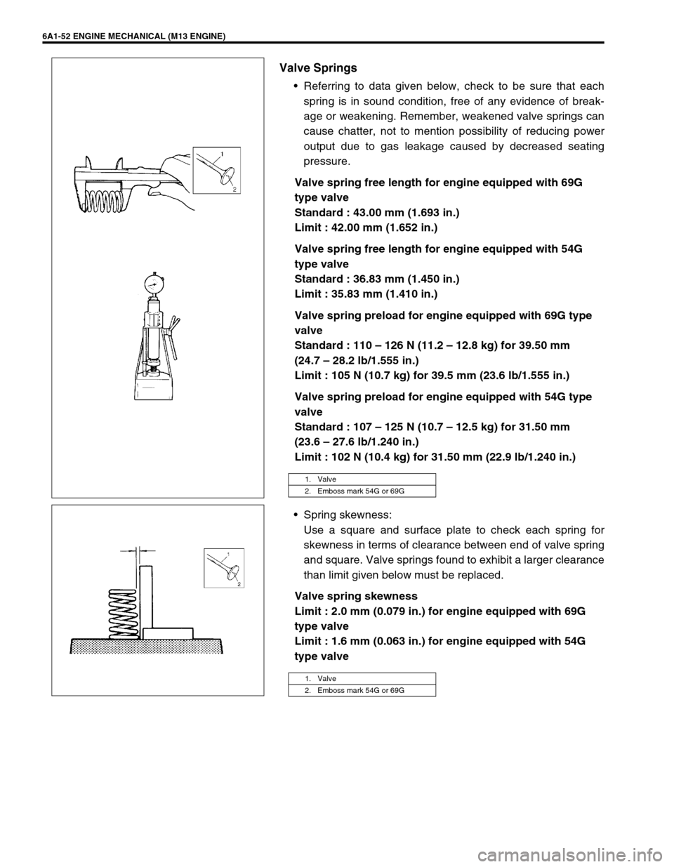
Referring to data given below, check to be sure that each
spring is in sound condition, free of any evidence of break-
age or weakening. Remember, weakened valve springs can
cause chatter, not to mention possibility of reducing power
output due to gas leakage caused by decreased seating
pressure.
Valve spring free length for engine equipped with 69G
type valve
Standard : 43.00 mm (1.693 in.)
Limit : 42.00 mm (1.652 in.)
Valve spring free length for engine equipped with 54G
type valve
Standard : 36.83 mm (1.450 in.)
Limit : 35.83 mm (1.410 in.)
Valve spring preload for engine equipped with 69G type
valve
Standard : 110 – 126 N (11.2 – 12.8 kg) for 39.50 mm
(24.7 – 28.2 lb/1.555 in.)
Limit : 105 N (10.7 kg) for 39.5 mm (23.6 lb/1.555 in.)
Valve spring preload for engine equipped with 54G type
valve
Standard : 107 – 125 N (10.7 – 12.5 kg) for 31.50 mm
(23.6 – 27.6 lb/1.240 in.)
Limit : 102 N (10.4 kg) for 31.50 mm (22.9 lb/1.240 in.)
Spring skewness:
Use a square and surface plate to check each spring for
skewness in terms of clearance between end of valve spring
and square. Valve springs found to exhibit a larger clearance
than limit given below must be replaced.
Valve spring skewness
Limit : 2.0 mm (0.079 in.) for engine equipped with 69G
type valve
Limit : 1.6 mm (0.063 in.) for engine equipped with 54G
type valve
1. Valve
2. Emboss mark 54G or 69G
1. Valve
2. Emboss mark 54G or 69G
Page 554 of 698
ENGINE MECHANICAL (M13 ENGINE) 6A1-53
ASSEMBLY
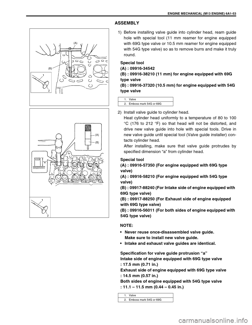
1) Before installing valve guide into cylinder head, ream guide
hole with special tool (11 mm reamer for engine equipped
with 69G type valve or 10.5 mm reamer for engine equipped
with 54G type valve) so as to remove burrs and make it truly
round.
Special tool
(A) : 09916-34542
(B) : 09916-38210 (11 mm) for engine equipped with 69G
type valve
(B) : 09916-37320 (10.5 mm) for engine equipped with 54G
type valve
2) Install valve guide to cylinder head.
Heat cylinder head uniformly to a temperature of 80 to 100
°C (176 to 212 °F) so that head will not be distorted, and
drive new valve guide into hole with special tools. Drive in
new valve guide until special tool (Valve guide installer) con-
tacts cylinder head.
After installing, make sure that valve guide protrudes by
specified dimension “a” from cylinder head.
Special tool
(A) : 09916-57350 (For engine equipped with 69G type
valve)
(A) : 09916-58210 (For engine equipped with 54G type
valve)
(B) : 09917-88240 (For Intake side of engine equipped with
69G type valve)
(B) : 09917-88250 (For Exhaust side of engine equipped
with 69G type valve)
(B) : 09916-56011 (For both sides of engine equipped with
54G type valve)
Specification for valve guide protrusion “a”
Intake side of engine equipped with 69G type valve
: 17.5 mm (0.71 in.)
Exhaust side of engine equipped with 69G type valve
: 14.5 mm (0.57 in.)
Both sides of engine equipped with 54G type valve
: 11.1 – 11.5 mm (0.44 – 0.45 in.)
1. Valve
2. Emboss mark 54G or 69G
NOTE:
Never reuse once-disassembled valve guide.
Make sure to install new valve guide.
Intake and exhaust valve guides are identical.
1. Valve
2. Emboss mark 54G or 69G
Page 555 of 698
6A1-54 ENGINE MECHANICAL (M13 ENGINE)
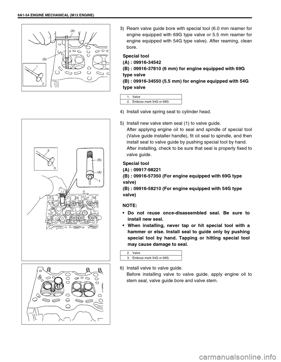
3) Ream valve guide bore with special tool (6.0 mm reamer for
engine equipped with 69G type valve or 5.5 mm reamer for
engine equipped with 54G type valve). After reaming, clean
bore.
Special tool
(A) : 09916-34542
(B) : 09916-37810 (6 mm) for engine equipped with 69G
type valve
(B) : 09916-34550 (5.5 mm) for engine equipped with 54G
type valve
4) Install valve spring seat to cylinder head.
5) Install new valve stem seal (1) to valve guide.
After applying engine oil to seal and spindle of special tool
(Valve guide installer handle), fit oil seal to spindle, and then
install seal to valve guide by pushing special tool by hand.
After installing, check to be sure that seal is properly fixed to
valve guide.
Special tool
(A) : 09917-98221
(B) : 09916-57350 (For engine equipped with 69G type
valve)
(B) : 09916-58210 (For engine equipped with 54G type
valve)
6) Install valve to valve guide.
Before installing valve to valve guide, apply engine oil to
stem seal, valve guide bore and valve stem.
1. Valve
2. Emboss mark 54G or 69G
NOTE:
Do not reuse once-disassembled seal. Be sure to
install new seal.
When installing, never tap or hit special tool with a
hammer or else. Install seal to guide only by pushing
special tool by hand. Tapping or hitting special tool
may cause damage to seal.
2. Valve
3. Emboss mark 54G or 69G
Page 591 of 698
6B-2 ENGINE COOLING
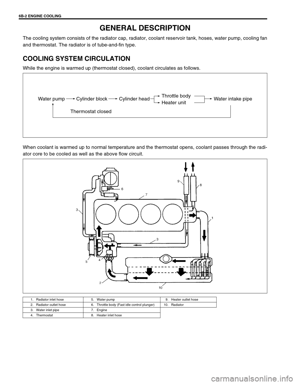
GENERAL DESCRIPTION
The cooling system consists of the radiator cap, radiator, coolant reservoir tank, hoses, water pump, cooling fan
and thermostat. The radiator is of tube-and-fin type.
COOLING SYSTEM CIRCULATION
While the engine is warmed up (thermostat closed), coolant circulates as follows.
When coolant is warmed up to normal temperature and the thermostat opens, coolant passes through the radi-
ator core to be cooled as well as the above flow circuit.
1. Radiator inlet hose 5. Water pump 9. Heater outlet hose
2. Radiator outlet hose 6. Throttle body (Fast idle control plunger) 10. Radiator
3. Water inlet pipe 7. Engine
4. Thermostat 8. Heater inlet hose
Water pump Cylinder block
Thermostat closedCylinder head Water intake pipeThrottle body
Heater unit
Page 610 of 698
ENGINE FUEL 6C-3
PRECAUTIONS
WARNING:
Before attempting service of any type on fuel system, the
followings should be always observed in order to reduce
the risk or fire and personal injury.
Disconnect negative cable at battery.
Do not smoke, and place no smoking signs near work
area.
Be sure to have CO
2 fire extinguisher handy.
Be sure to perform work in a well-ventilated area and
away from any open flames (such as gas hot heater).
Wear safety glasses.
To relieve fuel vapor pressure in fuel tank, remove fuel
filler cap from fuel filler neck and then reinstall it.
As fuel feed line is still under high fuel pressure even
after engine was stopped, loosening or disconnecting
fuel feed line directly may cause dangerous spout of
fuel to occur where loosened or disconnected.
Before loosening or disconnecting fuel feed line, make
sure to relieve fuel pressure “FUEL PRESSURE
RELIEF PROCEDURE” in Section 6.
A small amount of fuel may be released after the fuel
line is disconnected. In order to reduce the chance of
personal injury, cover the fitting to be disconnected
with a shop cloth. Be sure to put that cloth in an
approved container when disconnection is completed.
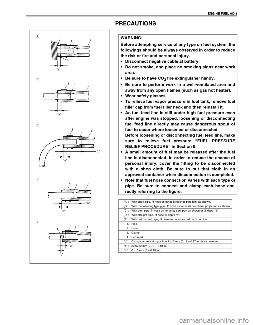
Note that fuel hose connection varies with each type of
pipe. Be sure to connect and clamp each hose cor-
rectly referring to the figure.
[A] : With short pipe, fit hose as far as it reaches pipe joint as shown.
[B] : With the following type pipe, fit hose as far as its peripheral projection as shown.
[C] : With bent pipe, fit hose as far as its bent part as shown or till depth “b”.
[D] : With straight pipe, fit hose till depth “b”.
[E] : With red marked pipe, fit hose end reaches red mark on pipe.
1. Pipe
2. Hose
3. Clamp
4. Ped mark
“a” : Clamp securely at a position 3 to 7 mm (0.12 – 0.27 in.) from hose end.
“b” : 20 to 30 mm (0.79 – 1.18 in.)
“c” : 0 to 5 mm (0 – 0.19 in.)
Page 627 of 698
6E1-6 ENGINE AND EMISSION CONTROL SYSTEM
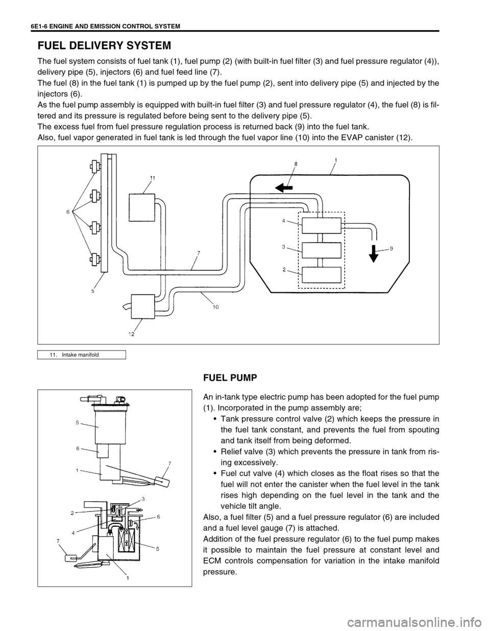
FUEL DELIVERY SYSTEM
The fuel system consists of fuel tank (1), fuel pump (2) (with built-in fuel filter (3) and fuel pressure regulator (4)),
delivery pipe (5), injectors (6) and fuel feed line (7).
The fuel (8) in the fuel tank (1) is pumped up by the fuel pump (2), sent into delivery pipe (5) and injected by the
injectors (6).
As the fuel pump assembly is equipped with built-in fuel filter (3) and fuel pressure regulator (4), the fuel (8) is fil-
tered and its pressure is regulated before being sent to the delivery pipe (5).
The excess fuel from fuel pressure regulation process is returned back (9) into the fuel tank.
Also, fuel vapor generated in fuel tank is led through the fuel vapor line (10) into the EVAP canister (12).
FUEL PUMP
An in-tank type electric pump has been adopted for the fuel pump
(1). Incorporated in the pump assembly are;
Tank pressure control valve (2) which keeps the pressure in
the fuel tank constant, and prevents the fuel from spouting
and tank itself from being deformed.
Relief valve (3) which prevents the pressure in tank from ris-
ing excessively.
Fuel cut valve (4) which closes as the float rises so that the
fuel will not enter the canister when the fuel level in the tank
rises high depending on the fuel level in the tank and the
vehicle tilt angle.
Also, a fuel filter (5) and a fuel pressure regulator (6) are included
and a fuel level gauge (7) is attached.
Addition of the fuel pressure regulator (6) to the fuel pump makes
it possible to maintain the fuel pressure at constant level and
ECM controls compensation for variation in the intake manifold
pressure.
11. Intake manifold
Page 630 of 698
ENGINE AND EMISSION CONTROL SYSTEM 6E1-9
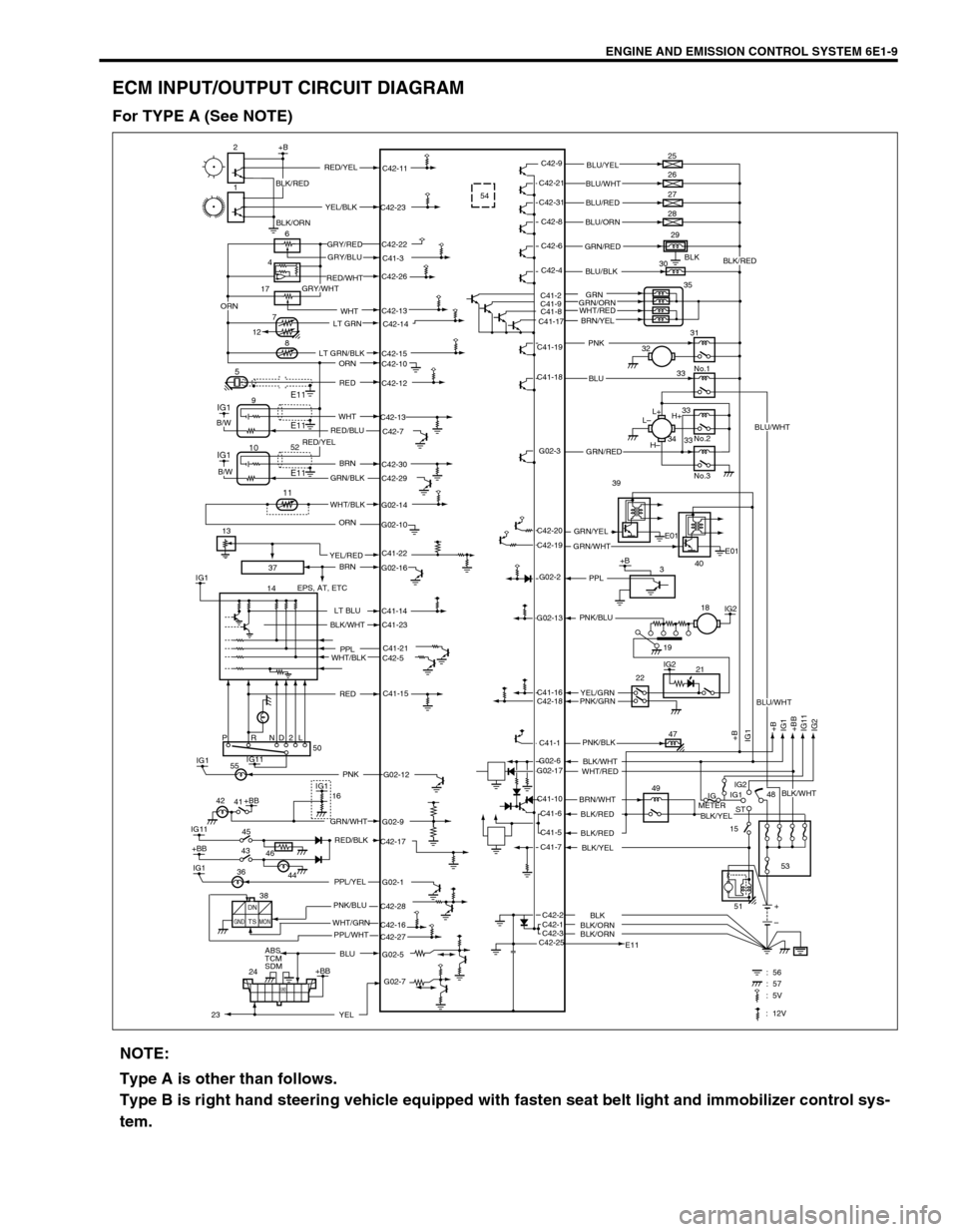
ECM INPUT/OUTPUT CIRCUIT DIAGRAM
For TYPE A (See NOTE)
37
C41-23
G02-12 IG1PNK 5554
BLK
C41-2
C41-9
C41-8
C41-17C42-13
17
2+B
1
6
8
5
IG1
IG1
14C42-9
C42-11
C42-23
C42-22
C41-3
C42-26
C42-14
C42-15
C42-10
C42-12
C42-13
C42-7
C42-30
C42-29
G02-14
G02-10
G02-16
C41-14
C41-21
C42-5
C41-15
G02-9
C42-17
G02-1
C42-28
C42-27 C42-16
G02-5C42-21
C42-31
C42-8
C42-6
C42-4
C41-19
C41-18
G02-3
G02-2
G02-13
C41-16
C42-18
C41-1
C41-10
C41-6
C41-5
C41-7
C42-1 C42-2
C42-3
C42-25G02-6
G02-173E01
E01 C42-20
C42-19L+
L–
H–H+ 25
26
27
28
29
30
35
31
No.1
No.2
No.3 32
33
33
33 34
IG2
IG2
+B
+B
IG1
+BB
IG11
IG2 IG1
21
47
49
IG
METERIG1
ST
15IG2
48
53
E11+
– 2218
PRND2L
IG11
IG11
+BB
IG145 41
ABS
TCM
SDM
24IG1
+BB50
16
E11
E1194
7
12
+BB
GND
: 56 : 57
IG1
E11 10
11
+B RED/YELBLU/YEL
BLU/WHT
BLU/RED
BLU/ORN
GRN/RED
BLU/BLK
PNK
BLU
GRN/RED
GRN/YEL39
40 GRN/WHT
PPL
YEL/GRN PNK/BLU
PNK/GRN
PNK/BLK
BLK/WHT
WHT/RED
BRN/WHT
BLK/RED
BLK/RED
BLK/YEL
BLK/ORNBLK
BLK/ORN YEL/BLK
GRY/RED
GRY/BLU
RED/WHT
GRY/WHT
LT GRN
LT GRN/BLK
ORN
RED
WHT
RED/BLU
BRN
GRN/BLK
WHT/BLK
ORN
BRN
EPS, AT, ETC
LT BLU
PPL
WHT/BLK
GRN/WHT
RED/BLK
PPL/YEL
PNK/BLU
WHT/GRN
BLU
B/W
B/W
BLK/WHT
RED
42
46 43
44 36
DN
TSGND MONPPL/WHT 38
G02-7
YEL
BLK/RED
GRN
GRN/ORN
BRN/YEL
51
2352
C41-22YEL/RED 13WHT
19
ORN
: 5V
: 12V
BLU/WHT
BLK/WHT
BLU/WHT
BLK/YEL
BLK/RED
BLK/ORN
WHT/RED
RED/YEL
NOTE:
Type A is other than follows.
Type B is right hand steering vehicle equipped with fasten seat belt light and immobilizer control sys-
tem.
Page 632 of 698
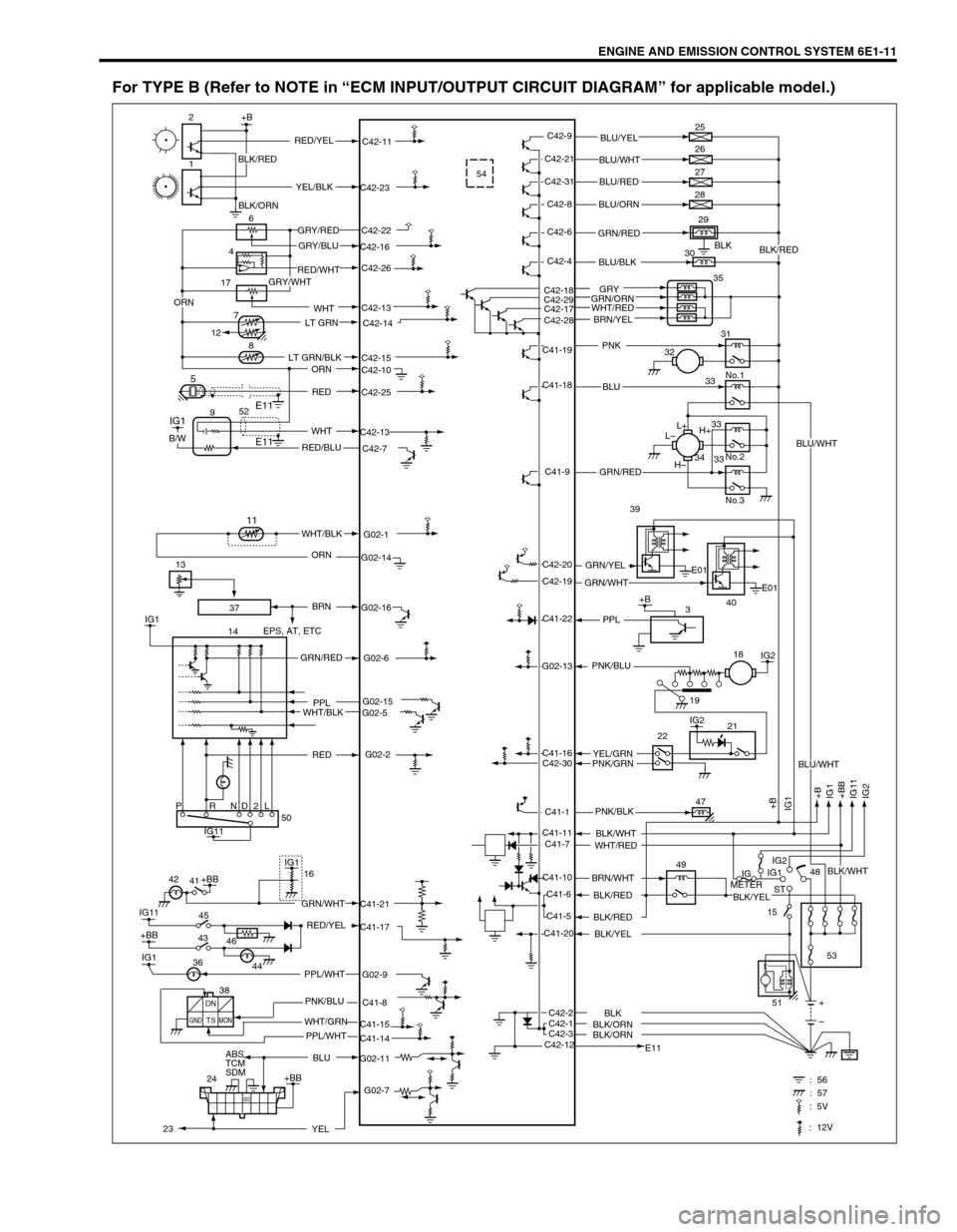
ENGINE AND EMISSION CONTROL SYSTEM 6E1-11
For TYPE B (Refer to NOTE in “ECM INPUT/OUTPUT CIRCUIT DIAGRAM” for applicable model.)
37
54
BLK
C42-18
C42-29
C42-17
C42-28
C42-13
17
2+B
1
6
8
5
IG1
IG1
14C42-9
C42-11
C42-23
C42-22
C42-16
C42-26
C42-14
C42-15
C42-10
C42-25
C42-13
C42-7
G02-1
G02-14
G02-16
G02-6
G02-15
G02-5
G02-2
C41-21
C41-17
G02-9
C41-8
C41-14 C41-15
G02-11C42-21
C42-31
C42-8
C42-6
C42-4
C41-19
C41-18
C41-9
C41-22
G02-13
C41-16
C42-30
C41-1
C41-10
C41-6
C41-5
C41-20
C42-1 C42-2
C42-3
C42-12 C41-11
C41-73E01
E01 C42-20
C42-19L+
L–
H–H+ 25
26
27
28
29
30
35
31
No.1
No.2
No.3 32
33
33
33 34
IG2
IG2
+B
+B
IG1
+BB
IG11
IG2 IG1
21
47
49
IG
METERIG1
ST
15IG2
48
53
E11+
– 2218
PRND2L
IG11
IG11
+BB
IG145 41
ABS
TCM
SDM
24IG1
+BB50
16
E11
E1194
7
12
52
+BB
GND
: 56 : 57
11
+B RED/YELBLU/YEL
BLU/WHT
BLU/RED
BLU/ORN
GRN/RED
BLU/BLK
PNK
BLU
GRN/RED
GRN/YEL39
40 GRN/WHT
PPL
YEL/GRN PNK/BLU
PNK/GRN
PNK/BLK
BLK/WHT
WHT/RED
BRN/WHT
BLK/RED
BLK/RED
BLK/YEL
BLK/ORNBLK
BLK/ORN YEL/BLK
GRY/RED
GRY/BLU
RED/WHT
GRY/WHT
LT GRN
LT GRN/BLK
ORN
RED
WHT
RED/BLU
WHT/BLK
ORN
BRN
EPS, AT, ETC
GRN/RED
PPL
WHT/BLK
GRN/WHT
RED/YEL
PPL/WHT
PNK/BLU
WHT/GRN
BLU
B/W
RED
42
46 43
44 36
DN
TS
GND MON
PPL/WHT 38
G02-7
YEL
BLK/RED
GRY
GRN/ORN
BRN/YEL
51
23
13WHT
19
ORN
: 5V
: 12V
BLU/WHT
BLK/WHT
BLU/WHT
BLK/YEL
BLK/RED
BLK/ORN
WHT/RED