steering wheel SUZUKI SWIFT 2000 1.G RG413 Service Repair Manual
[x] Cancel search | Manufacturer: SUZUKI, Model Year: 2000, Model line: SWIFT, Model: SUZUKI SWIFT 2000 1.GPages: 698, PDF Size: 16.01 MB
Page 208 of 698
FRONT SUSPENSION 3D-15
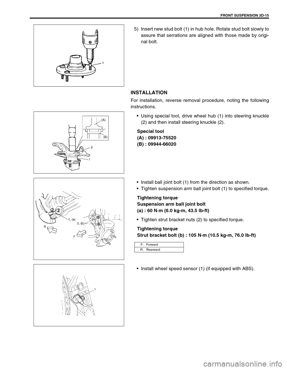
5) Insert new stud bolt (1) in hub hole. Rotate stud bolt slowly to
assure that serrations are aligned with those made by origi-
nal bolt.
INSTALLATION
For installation, reverse removal procedure, noting the following
instructions.
Using special tool, drive wheel hub (1) into steering knuckle
(2) and then install steering knuckle (2).
Special tool
(A) : 09913-75520
(B) : 09944-66020
Install ball joint bolt (1) from the direction as shown.
Tighten suspension arm ball joint bolt (1) to specified torque.
Tightening torque
Suspension arm ball joint bolt
(a) : 60 N·m (6.0 kg-m, 43.5 lb-ft)
Tighten strut bracket nuts (2) to specified torque.
Tightening torque
Strut bracket bolt (b) : 105 N·m (10.5 kg-m, 76.0 lb-ft)
Install wheel speed sensor (1) (if equipped with ABS).
F: Forward
R: Rearward
Page 209 of 698

3D-16 FRONT SUSPENSION
Connect tie rod end (1) to steering knuckle (2) and tighten tie
rod end castle nut (3) to specified torque.
Tightening torque
The rod end castle nut (a) : 43 N·m (4.3 kg-m, 31.5 lb-ft)
Install new split pin (4).
Install brake disc (2) and brake caliper (3).
Tighten brake caliper bolt to specified torque.
Tightening torque
Brake caliper bolt : 85 N·m (8.5 kg-m, 61.5 lb-ft)
Depress foot brake pedal and hold it there.
Tighten new drive shaft nut (1) to specified torque.
Tightening torque
Drive shaft nut (a) : 175 N·m (17.5 kg-m, 127.0 lb-ft)
Caulk drive shaft nut (1) as shown.
Caulking specification
“a” : 0.5 mm (0.02 in.) or more
Tightening wheel nut to specified torque.
Tightening torque
Wheel nut : 85 N·m (8.5 kg-m, 61.5 lb-ft)
SUSPENSION CONTROL ARM / BUSHING
REMOVAL
1) Remove stabilizer bar. Refer to “STABILIZER BAR AND/OR
BUSHINGS” in this section.
2) Remove suspension control arm ball joint bolt (1).
CAUTION:
Never reuse drive shaft nut (1).
CAUTION:
Be careful while caulking nut so that no crack will occur
in caulked part of nut. Cracked nut must be replaced with
new one.
F: Forward
Page 211 of 698

3D-18 FRONT SUSPENSION
2) Press-fit bushing so that dimensions “A” and “B” in figure
become equal.
INSTALLATION
1) Install body side of suspension control arm but tighten sus-
pension control arm bolt (1) only temporarily.
2) Install suspension control arm ball joint to steering knuckle.
Align ball stud groove with steering knuckle bolt hole. Then
install ball joint bolt (1) from the direction as shown in figure.
Tighten suspension arm ball joint bolt (1) to specified torque.
Tightening torque
Suspension arm ball joint bolt
(a) : 60 N·m (6.0 kg-m, 43.5 lb-ft)
3) Install stabilizer bar, referring to “STABILIZER BAR AND/OR
BUSHINGS” in this section.
4) Lower hoist and vehicle in non-loaded condition, tighten con-
trol arm bolt (1) to specified torque.
Tightening torque
Control arm bolt (a) : 60 N·m (6.0 kg-m, 43.5 lb-ft)
5) Confirm front end (wheel) alignment referring to Section 3A.
F: Forward
Page 250 of 698

WHEELS AND TIRES 3F-5
MAINTENANCE AND MINOR ADJUSTMENTS
WHEEL MAINTENANCE
Wheel repairs that use welding, heating, or peening are not approved. All damaged wheels should be replaced.
WHEEL ATTACHING STUDS
If a broken stud is found, see Section 3E (rear) or Section 3D (front) for Note and Replacement procedure.
MATCHED TIRES AND WHEELS
Tires and wheels are match mounted at the assembly plant.
This means that the radially stiffest part of the tire, or “high spot”,
is matched to the smallest radius or “low spot” of the wheel.
This is done to provide the smoothest possible ride.
The “high spot” of the tire is originally marked by paint dot (1) on
the outboard sidewall. This paint dot will eventually wash off the
tire.
The “ow spot” of the wheel is originally marked by paint dot (2) on
the wheel rim-flange. Properly assembled, the wheel rims’ paint
dot should be aligned with the tires’ paint dot as shown in left fig-
ure.
Whenever a tire is dismounted from its wheel, it should be
remounted so that the tire and wheel are matched. If the tire’s
paint dot cannot be located, a line should be scribed on the tire
and wheel before dismounting to assure that it is remounted in
the same position.
TIRE MAINTENANCE
TIRE PLACARD
The “Tire Placard” is located on the left door (right door for right-hand side steering vehicle) lock pillar and
should be referred to tire information.
The placard lists the maximum load, tire size and cold tire pressure where applicable.
NOTE:
Whether rim size and/or maximum load are listed or not depends on regulations of each country.
Page 251 of 698
3F-6 WHEELS AND TIRES
INFLATION OF TIRES
The pressure recommended for any model is carefully calculated to give a satisfactory ride, stability, steering,
tread wear, tire life and resistance to bruises.
Tire pressure, with tires cold, (after vehicle has set for 3 hours or more, or driven less than one mile) should be
checked monthly or before any extended trip. Set to the specifications on the “Tire Placard” located on the left
door (right door for right-hand side steering vehicle) lock pillar.
It is normal for tire pressure to increase when the tires become hot during driving.
Do not bleed or reduce tire pressure after driving. Bleeding reduces the “Cold Inflation Pressure”.
Higher than recommended pressure can cause :
Hard ride
Tire bruising or carcass damage
Rapid tread wear at center of tire
Unequal pressure on same axle can cause :
Uneven braking
Steering lead
Reduced handling
Swerve on acceleration
Lower than recommended pressure can cause :
Tire squeal on turns
Hard Steering
Rapid and uneven wear on the edges of the tread
Tire rim bruises and rupture
Tire cord breakage
High tire temperature
Reduced handling
High fuel consumption
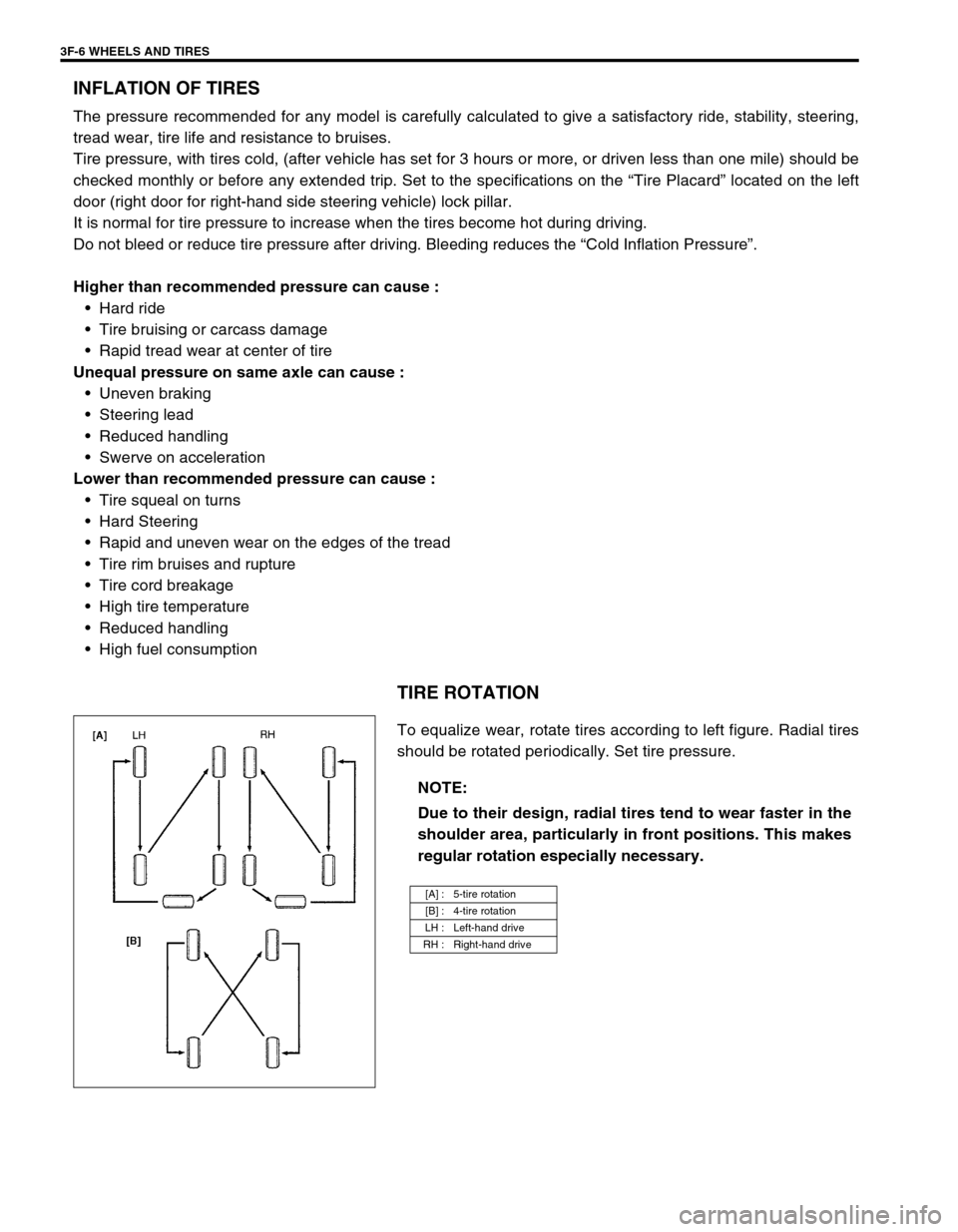
TIRE ROTATION
To equalize wear, rotate tires according to left figure. Radial tires
should be rotated periodically. Set tire pressure.
NOTE:
Due to their design, radial tires tend to wear faster in the
shoulder area, particularly in front positions. This makes
regular rotation especially necessary.
[A] : 5-tire rotation
[B] : 4-tire rotation
LH : Left-hand drive
RH : Right-hand drive
Page 257 of 698
4A-4 FRONT DRIVE SHAFT
DRIVE SHAFT ASSEMBLY
REMOVAL
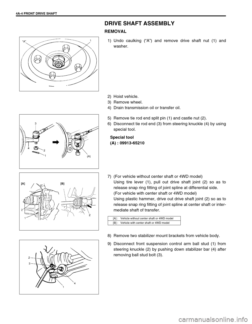
1) Undo caulking (“A”) and remove drive shaft nut (1) and
washer.
2) Hoist vehicle.
3) Remove wheel.
4) Drain transmission oil or transfer oil.
5) Remove tie rod end split pin (1) and castle nut (2).
6) Disconnect tie rod end (3) from steering knuckle (4) by using
special tool.
Special tool
(A) : 09913-65210
7) (For vehicle without center shaft or 4WD model)
Using tire lever (1), pull out drive shaft joint (2) so as to
release snap ring fitting of joint spline at differential side.
(For vehicle with center shaft or 4WD model)
Using plastic hammer, drive out drive shaft joint (2) so as to
release snap ring fitting of joint spline at center shaft or inter-
mediate shaft of transfer.
8) Remove two stabilizer mount brackets from vehicle body.
9) Disconnect front suspension control arm ball stud (1) from
steering knuckle (2) by pushing down stabilizer bar (4) after
removing ball stud bolt (3).
[A] : Vehicle without center shaft or 4WD model
[B] : Vehicle with center shaft or 4WD model
Page 279 of 698
5-6 BRAKES
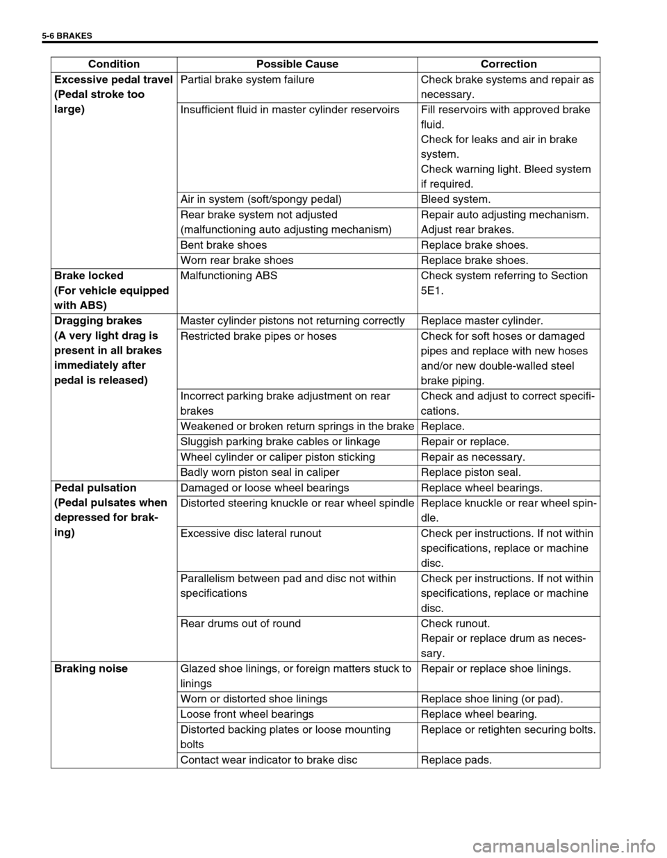
Excessive pedal travel
(Pedal stroke too
large)Partial brake system failure Check brake systems and repair as
necessary.
Insufficient fluid in master cylinder reservoirs Fill reservoirs with approved brake
fluid.
Check for leaks and air in brake
system.
Check warning light. Bleed system
if required.
Air in system (soft/spongy pedal) Bleed system.
Rear brake system not adjusted
(malfunctioning auto adjusting mechanism)Repair auto adjusting mechanism.
Adjust rear brakes.
Bent brake shoes Replace brake shoes.
Worn rear brake shoes Replace brake shoes.
Brake locked
(For vehicle equipped
with ABS)Malfunctioning ABS Check system referring to Section
5E1.
Dragging brakes
(A very light drag is
present in all brakes
immediately after
pedal is released)Master cylinder pistons not returning correctly Replace master cylinder.
Restricted brake pipes or hoses Check for soft hoses or damaged
pipes and replace with new hoses
and/or new double-walled steel
brake piping.
Incorrect parking brake adjustment on rear
brakesCheck and adjust to correct specifi-
cations.
Weakened or broken return springs in the brake Replace.
Sluggish parking brake cables or linkage Repair or replace.
Wheel cylinder or caliper piston sticking Repair as necessary.
Badly worn piston seal in caliper Replace piston seal.
Pedal pulsation
(Pedal pulsates when
depressed for brak-
ing)Damaged or loose wheel bearings Replace wheel bearings.
Distorted steering knuckle or rear wheel spindle Replace knuckle or rear wheel spin-
dle.
Excessive disc lateral runout Check per instructions. If not within
specifications, replace or machine
disc.
Parallelism between pad and disc not within
specificationsCheck per instructions. If not within
specifications, replace or machine
disc.
Rear drums out of round Check runout.
Repair or replace drum as neces-
sary.
Braking noise
Glazed shoe linings, or foreign matters stuck to
liningsRepair or replace shoe linings.
Worn or distorted shoe linings Replace shoe lining (or pad).
Loose front wheel bearings Replace wheel bearing.
Distorted backing plates or loose mounting
boltsReplace or retighten securing bolts.
Contact wear indicator to brake disc Replace pads. Condition Possible Cause Correction
Page 282 of 698
BRAKES 5-9
EXCESSIVE PEDAL TRAVEL INSPECTION
1) Start engine.
2) Depress brake pedal a few times.
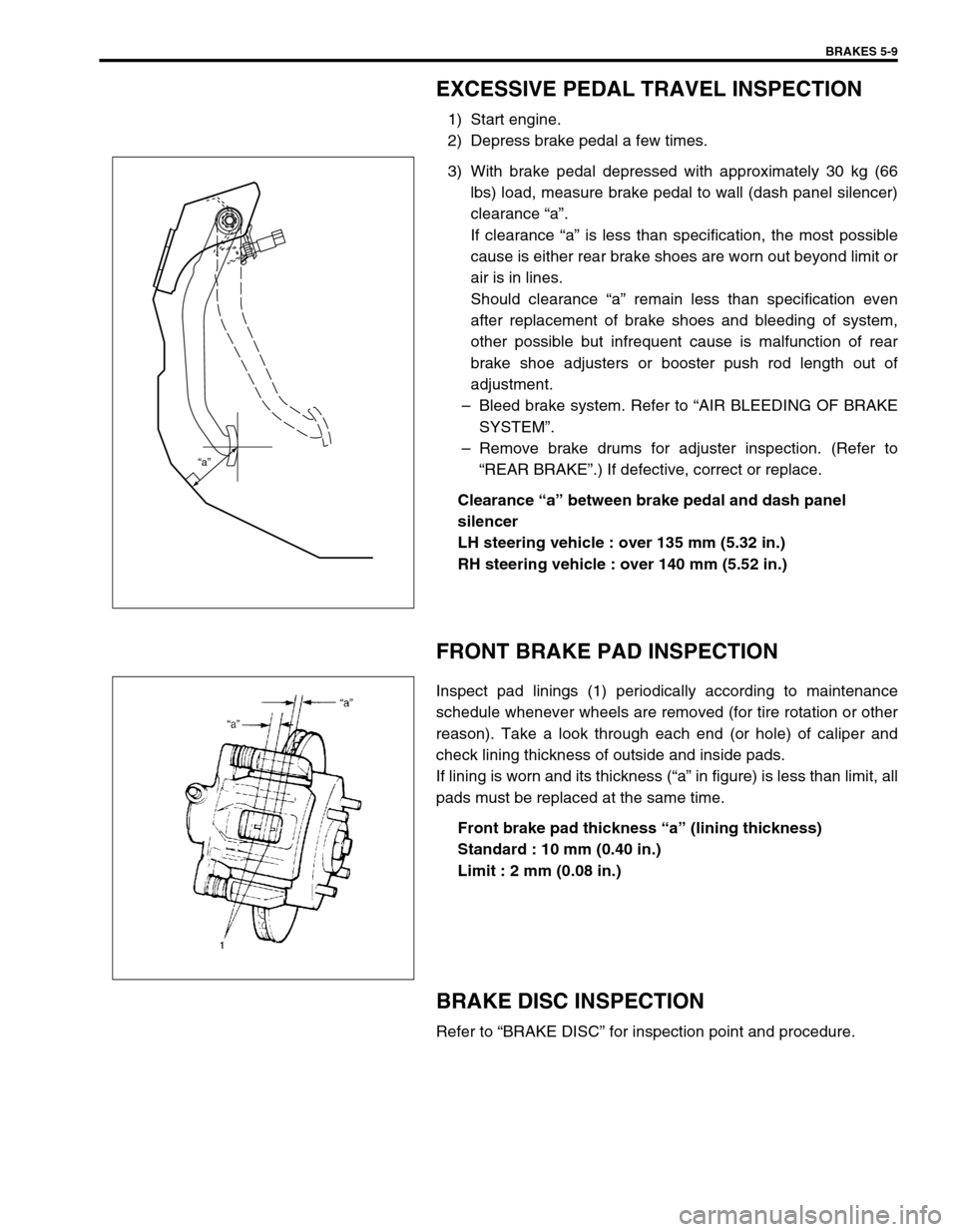
3) With brake pedal depressed with approximately 30 kg (66
lbs) load, measure brake pedal to wall (dash panel silencer)
clearance “a”.
If clearance “a” is less than specification, the most possible
cause is either rear brake shoes are worn out beyond limit or
air is in lines.
Should clearance “a” remain less than specification even
after replacement of brake shoes and bleeding of system,
other possible but infrequent cause is malfunction of rear
brake shoe adjusters or booster push rod length out of
adjustment.
–Bleed brake system. Refer to “AIR BLEEDING OF BRAKE
SYSTEM”.
–Remove brake drums for adjuster inspection. (Refer to
“REAR BRAKE”.) If defective, correct or replace.
Clearance “a” between brake pedal and dash panel
silencer
LH steering vehicle : over 135 mm (5.32 in.)
RH steering vehicle : over 140 mm (5.52 in.)
FRONT BRAKE PAD INSPECTION
Inspect pad linings (1) periodically according to maintenance
schedule whenever wheels are removed (for tire rotation or other
reason). Take a look through each end (or hole) of caliper and
check lining thickness of outside and inside pads.
If lining is worn and its thickness (“a” in figure) is less than limit, all
pads must be replaced at the same time.
Front brake pad thickness “a” (lining thickness)
Standard : 10 mm (0.40 in.)
Limit : 2 mm (0.08 in.)
BRAKE DISC INSPECTION
Refer to “BRAKE DISC” for inspection point and procedure.
“a”
Page 290 of 698
BRAKES 5-17
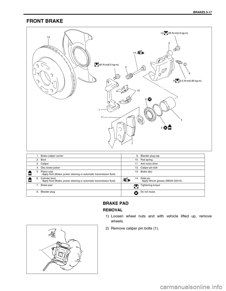
FRONT BRAKE
BRAKE PAD
REMOVAL
1) Loosen wheel nuts and with vehicle lifted up, remove
wheels.
2) Remove caliper pin bolts (1).
1. Brake caliper carrier 9. Bleeder plug cap
2. Boot 10. Pad spring
3. Caliper 11. Anti noise shim
4. Disc brake piston 12. Caliper pin bolt
5. Piston seal
: Apply fluid (Brake, power steering or automatic transmission fluid).13. Brake disc
6. Cylinder boot
: Apply fluid (Brake, power steering or automatic transmission fluid).14. Slide pin
: Apply lithium grease (99000-25010).
7. Brake pad Tightening torque
8. Bleeder plugDo not reuse.
9
1
7
13
2
143
1226 N·m(2.6 kg-m)
85 N·m(8.5 kg-m)
8
8.5 N·m(0.85 kg-m)
10
5 4
6
11
Page 297 of 698

5-24 BRAKES
INSPECTION
Using magnetic stand and with dial gauge positioned at
about 10 mm (0.39 in.) inward from periphery of disc, mea-
sure deflection of disc.
If limit value is exceeded, replace correct or replace.
Disc deflection
Limit : 0.10 mm (0.004 in.) max.
Special tool
(A) : 09900-20606
(B) : 09900-20701
Using micrometer, measure thickness of brake disc.
If limit value is exceeded, replace brake disc.
Brake disc thickness
Standard : 17.0 mm (0.67 in.)
Limit : 15.0 mm (0.59 in.)
INSTALLATION
1) Install disc to wheel hub.
2) Install caliper assembly to steering knuckle.
3) Torque caliper carrier bolts to specification.
Tightening torque
Caliper carrier bolts (a) : 85 N·m (8.5 kg-m, 61.5 Ib-ft)
4) Torque front wheel nuts to specification.
Tightening torque
Wheel nuts (b) : 85 N·m (8.5 kg-m, 61.5 Ib-ft)
5) Upon completion of installation, perform brake test.