Ecm SUZUKI SWIFT 2000 1.G RG413 Service Workshop Manual
[x] Cancel search | Manufacturer: SUZUKI, Model Year: 2000, Model line: SWIFT, Model: SUZUKI SWIFT 2000 1.GPages: 698, PDF Size: 16.01 MB
Page 15 of 698
0A-12 GENERAL INFORMATION
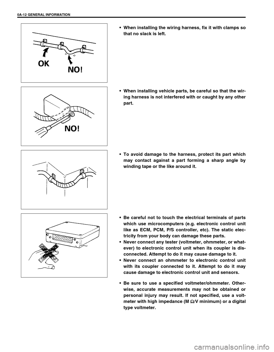
When installing the wiring harness, fix it with clamps so
that no slack is left.
When installing vehicle parts, be careful so that the wir-
ing harness is not interfered with or caught by any other
part.
To avoid damage to the harness, protect its part which
may contact against a part forming a sharp angle by
winding tape or the like around it.
Be careful not to touch the electrical terminals of parts
which use microcomputers (e.g. electronic control unit
like as ECM, PCM, P/S controller, etc). The static elec-
tricity from your body can damage these parts.
Never connect any tester (voltmeter, ohmmeter, or what-
ever) to electronic control unit when its coupler is dis-
connected. Attempt to do it may cause damage to it.
Never connect an ohmmeter to electronic control unit
with its coupler connected to it. Attempt to do it may
cause damage to electronic control unit and sensors.
Be sure to use a specified voltmeter/ohmmeter. Other-
wise, accurate measurements may not be obtained or
personal injury may result. If not specified, use a volt-
meter with high impedance (M
Ω/
Ω/Ω/ Ω/V minimum) or a digital
type voltmeter.
Page 17 of 698
0A-14 GENERAL INFORMATION
When checking system circuits including an electronic control unit
such as ECM, TCM, ABS control module, etc., it is important to
perform careful check, starting with items which are easier to
check.
1) Disconnect negative (–) cable from battery
2) Check each connector at both ends of the circuit being
checked for loose connection. Also check lock condition of
connector if equipped with connector lock.
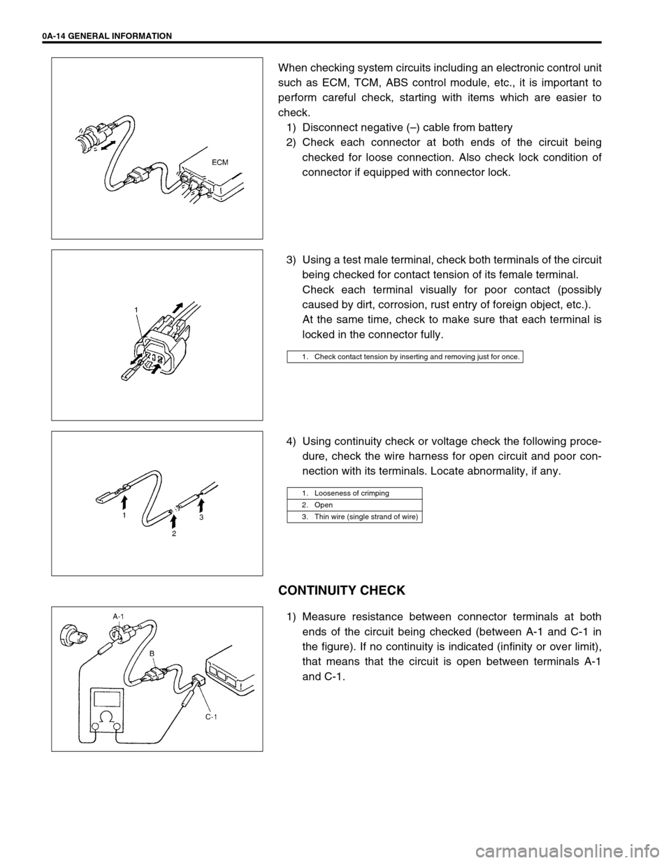
3) Using a test male terminal, check both terminals of the circuit
being checked for contact tension of its female terminal.
Check each terminal visually for poor contact (possibly
caused by dirt, corrosion, rust entry of foreign object, etc.).
At the same time, check to make sure that each terminal is
locked in the connector fully.
4) Using continuity check or voltage check the following proce-
dure, check the wire harness for open circuit and poor con-
nection with its terminals. Locate abnormality, if any.
CONTINUITY CHECK
1) Measure resistance between connector terminals at both
ends of the circuit being checked (between A-1 and C-1 in
the figure). If no continuity is indicated (infinity or over limit),
that means that the circuit is open between terminals A-1
and C-1.
1. Check contact tension by inserting and removing just for once.
1. Looseness of crimping
2. Open
3. Thin wire (single strand of wire)
Page 25 of 698
0A-22 GENERAL INFORMATION
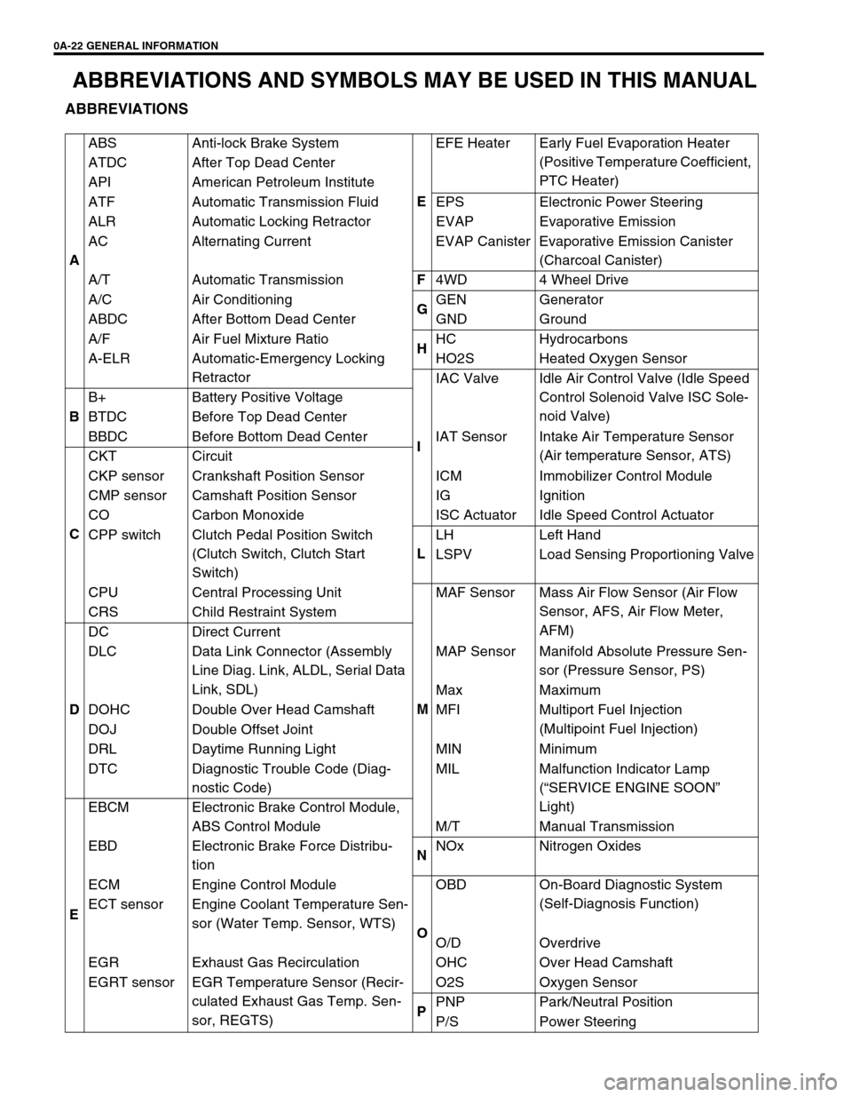
ABBREVIATIONS AND SYMBOLS MAY BE USED IN THIS MANUAL
ABBREVIATIONS
AABS Anti-lock Brake System
EEFE Heater Early Fuel Evaporation Heater
(Positive Temperature Coefficient,
PTC Heater) ATDC After Top Dead Center
API American Petroleum Institute
ATF Automatic Transmission Fluid EPS Electronic Power Steering
ALR Automatic Locking Retractor EVAP Evaporative Emission
AC Alternating Current EVAP Canister Evaporative Emission Canister
(Charcoal Canister)
A/T Automatic TransmissionF
4WD 4 Wheel Drive
A/C Air Conditioning
GGEN Generator
ABDC After Bottom Dead Center GND Ground
A/F Air Fuel Mixture Ratio
HHC Hydrocarbons
A-ELR Automatic-Emergency Locking
RetractorHO2S Heated Oxygen Sensor
IIAC Valve Idle Air Control Valve (Idle Speed
Control Solenoid Valve ISC Sole-
noid Valve)
BB+ Battery Positive Voltage
BTDC Before Top Dead Center
BBDC Before Bottom Dead Center IAT Sensor Intake Air Temperature Sensor
(Air temperature Sensor, ATS)
CCKT Circuit
CKP sensor Crankshaft Position Sensor ICM Immobilizer Control Module
CMP sensor Camshaft Position Sensor IG Ignition
CO Carbon Monoxide ISC Actuator Idle Speed Control Actuator
CPP switch Clutch Pedal Position Switch
(Clutch Switch, Clutch Start
Switch)LLH Left Hand
LSPV Load Sensing Proportioning Valve
CPU Central Processing Unit
MMAF Sensor Mass Air Flow Sensor (Air Flow
Sensor, AFS, Air Flow Meter,
AFM) CRS Child Restraint System
DDC Direct Current
DLC Data Link Connector (Assembly
Line Diag. Link, ALDL, Serial Data
Link, SDL)MAP Sensor Manifold Absolute Pressure Sen-
sor (Pressure Sensor, PS)
Max Maximum
DOHC Double Over Head Camshaft MFI Multiport Fuel Injection
(Multipoint Fuel Injection)
DOJ Double Offset Joint
DRL Daytime Running Light MIN Minimum
DTC Diagnostic Trouble Code (Diag-
nostic Code)MIL Malfunction Indicator Lamp
(“SERVICE ENGINE SOON”
Light)
EEBCM Electronic Brake Control Module,
ABS Control Module M/T Manual Transmission
EBD Electronic Brake Force Distribu-
tionNNOx Nitrogen Oxides
ECM Engine Control Module
OOBD On-Board Diagnostic System
(Self-Diagnosis Function)
ECT sensor Engine Coolant Temperature Sen-
sor (Water Temp. Sensor, WTS)
O/D Overdrive
EGR Exhaust Gas Recirculation OHC Over Head Camshaft
EGRT sensor EGR Temperature Sensor (Recir-
culated Exhaust Gas Temp. Sen-
sor, REGTS)O2S Oxygen Sensor
PPNP Park/Neutral Position
P/S Power Steering
Page 55 of 698
1A-4 HEATER AND VENTILATION
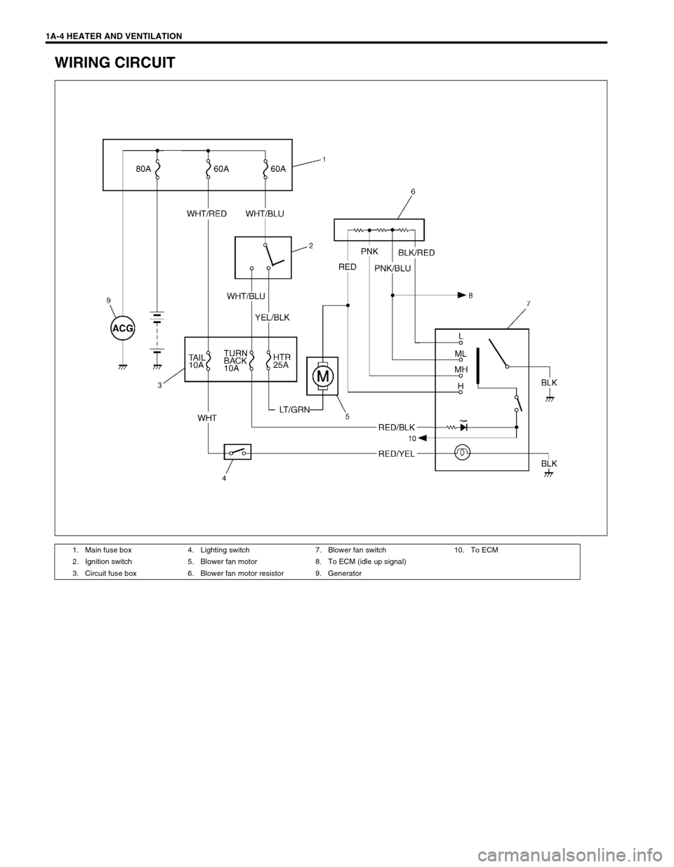
WIRING CIRCUIT
1. Main fuse box 4. Lighting switch 7. Blower fan switch 10. To ECM
2. Ignition switch 5. Blower fan motor 8. To ECM (idle up signal)
3. Circuit fuse box 6. Blower fan motor resistor 9. Generator
Page 66 of 698
AIR CONDITIONING (OPTIONAL) 1B-1
6F1
6F2
6G
1B
7A
7A1
7B1
7C1
7D
7E
7F
8A
8B
8C
8D
8E
9
10
10A
10B
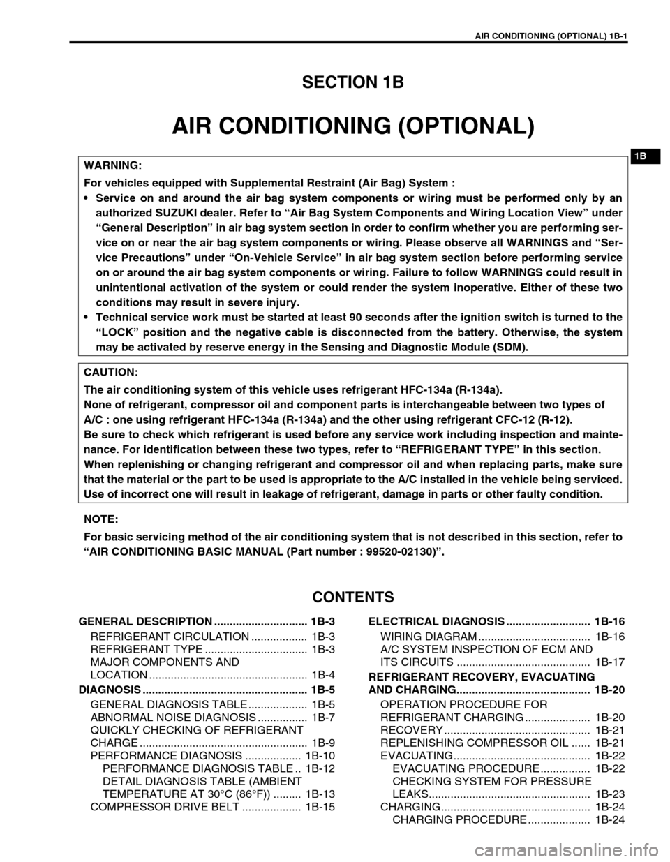
SECTION 1B
AIR CONDITIONING (OPTIONAL)
CONTENTS
GENERAL DESCRIPTION .............................. 1B-3
REFRIGERANT CIRCULATION .................. 1B-3
REFRIGERANT TYPE ................................. 1B-3
MAJOR COMPONENTS AND
LOCATION ................................................... 1B-4
DIAGNOSIS ..................................................... 1B-5
GENERAL DIAGNOSIS TABLE ................... 1B-5
ABNORMAL NOISE DIAGNOSIS ................ 1B-7
QUICKLY CHECKING OF REFRIGERANT
CHARGE ...................................................... 1B-9
PERFORMANCE DIAGNOSIS .................. 1B-10
PERFORMANCE DIAGNOSIS TABLE .. 1B-12
DETAIL DIAGNOSIS TABLE (AMBIENT
TEMPERATURE AT 30°C (86°F)) ......... 1B-13
COMPRESSOR DRIVE BELT ................... 1B-15ELECTRICAL DIAGNOSIS ........................... 1B-16
WIRING DIAGRAM .................................... 1B-16
A/C SYSTEM INSPECTION OF ECM AND
ITS CIRCUITS ........................................... 1B-17
REFRIGERANT RECOVERY, EVACUATING
AND CHARGING........................................... 1B-20
OPERATION PROCEDURE FOR
REFRIGERANT CHARGING ..................... 1B-20
RECOVERY ............................................... 1B-21
REPLENISHING COMPRESSOR OIL ...... 1B-21
EVACUATING............................................ 1B-22
EVACUATING PROCEDURE ................ 1B-22
CHECKING SYSTEM FOR PRESSURE
LEAKS.................................................... 1B-23
CHARGING................................................ 1B-24
CHARGING PROCEDURE .................... 1B-24 WARNING:
For vehicles equipped with Supplemental Restraint (Air Bag) System :
Service on and around the air bag system components or wiring must be performed only by an
authorized SUZUKI dealer. Refer to “Air Bag System Components and Wiring Location View” under
“General Description” in air bag system section in order to confirm whether you are performing ser-
vice on or near the air bag system components or wiring. Please observe all WARNINGS and “Ser-
vice Precautions” under “On-Vehicle Service” in air bag system section before performing service
on or around the air bag system components or wiring. Failure to follow WARNINGS could result in
unintentional activation of the system or could render the system inoperative. Either of these two
conditions may result in severe injury.
Technical service work must be started at least 90 seconds after the ignition switch is turned to the
“LOCK” position and the negative cable is disconnected from the battery. Otherwise, the system
may be activated by reserve energy in the Sensing and Diagnostic Module (SDM).
CAUTION:
The air conditioning system of this vehicle uses refrigerant HFC-134a (R-134a).
None of refrigerant, compressor oil and component parts is interchangeable between two types of
A/C : one using refrigerant HFC-134a (R-134a) and the other using refrigerant CFC-12 (R-12).
Be sure to check which refrigerant is used before any service work including inspection and mainte-
nance. For identification between these two types, refer to “REFRIGERANT TYPE” in this section.
When replenishing or changing refrigerant and compressor oil and when replacing parts, make sure
that the material or the part to be used is appropriate to the A/C installed in the vehicle being serviced.
Use of incorrect one will result in leakage of refrigerant, damage in parts or other faulty condition.
NOTE:
For basic servicing method of the air conditioning system that is not described in this section, refer to
“AIR CONDITIONING BASIC MANUAL (Part number : 99520-02130)”.
Page 70 of 698
AIR CONDITIONING (OPTIONAL) 1B-5
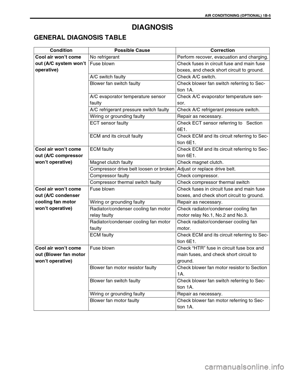
DIAGNOSIS
GENERAL DIAGNOSIS TABLE
Condition Possible Cause Correction
Cool air won’t come
out (A/C system won’t
operative)No refrigerant Perform recover, evacuation and charging.
Fuse blown Check fuses in circuit fuse and main fuse
boxes, and check short circuit to ground.
A/C switch faulty Check A/C switch.
Blower fan switch faulty Check blower fan switch referring to Sec-
tion 1A.
A/C evaporator temperature sensor
faultyCheck A/C evaporator temperature sen-
sor.
A/C refrigerant pressure switch faulty Check A/C refrigerant pressure switch.
Wiring or grounding faulty Repair as necessary.
ECT sensor faulty Check ECT sensor referring to Section
6E1.
ECM and its circuit faulty Check ECM and its circuit referring to Sec-
tion 6E1.
Cool air won’t come
out (A/C compressor
won’t operative)ECM faulty Check ECM and its circuit referring to Sec-
tion 6E1.
Magnet clutch faulty Check magnet clutch.
Compressor drive belt loosen or broken Adjust or replace drive belt.
Compressor faulty Check compressor.
Compressor thermal switch faulty Check compressor thermal switch
Cool air won’t come
out (A/C condenser
cooling fan motor
won’t operative)Fuse blown Check fuses in circuit fuse and main fuse
boxes, and check short circuit to ground.
Wiring or grounding faulty Repair as necessary.
Radiator/condenser cooling fan motor
relay faultyCheck radiator/condenser cooling fan
motor relay No.1, No.2 and No.3.
Radiator/condenser cooling fan motor
faultyCheck radiator/condenser cooling fan
motor.
ECM faulty Check ECM and its circuit referring to Sec-
tion 6E1.
Cool air won’t come
out (Blower fan motor
won’t operative)Fuse blown Check “HTR” fuse in circuit fuse box and
main fuses, and check short circuit to
ground.
Blower fan motor resistor faulty Check blower fan motor resistor to Section
1A.
Blower fan switch faulty Check blower fan switch referring to Sec-
tion 1A.
Wiring or grounding faulty Repair as necessary.
Blower fan motor faulty Check blower fan motor referring to Sec-
tion 1A.
Page 82 of 698
AIR CONDITIONING (OPTIONAL) 1B-17
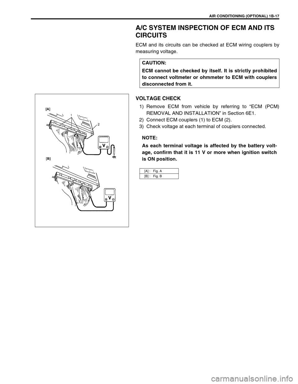
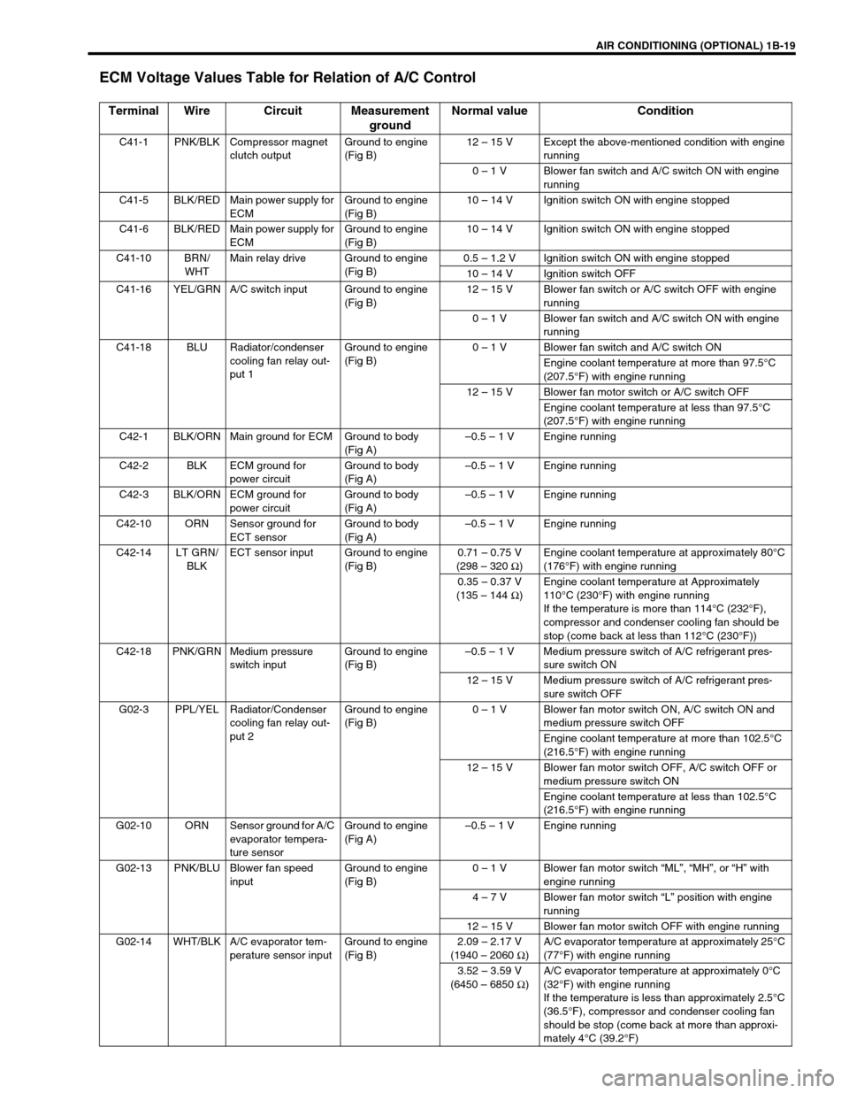
A/C SYSTEM INSPECTION OF ECM AND ITS
CIRCUITS
ECM and its circuits can be checked at ECM wiring couplers by
measuring voltage.
VOLTAGE CHECK
1) Remove ECM from vehicle by referring to “ECM (PCM)
REMOVAL AND INSTALLATION” in Section 6E1.
2) Connect ECM couplers (1) to ECM (2).
3) Check voltage at each terminal of couplers connected.CAUTION:
ECM cannot be checked by itself. It is strictly prohibited
to connect voltmeter or ohmmeter to ECM with couplers
disconnected from it.
NOTE:
As each terminal voltage is affected by the battery volt-
age, confirm that it is 11 V or more when ignition switch
is ON position.
[A] : Fig. A
[B] : Fig. B
Page 83 of 698
1B-18 AIR CONDITIONING (OPTIONAL)
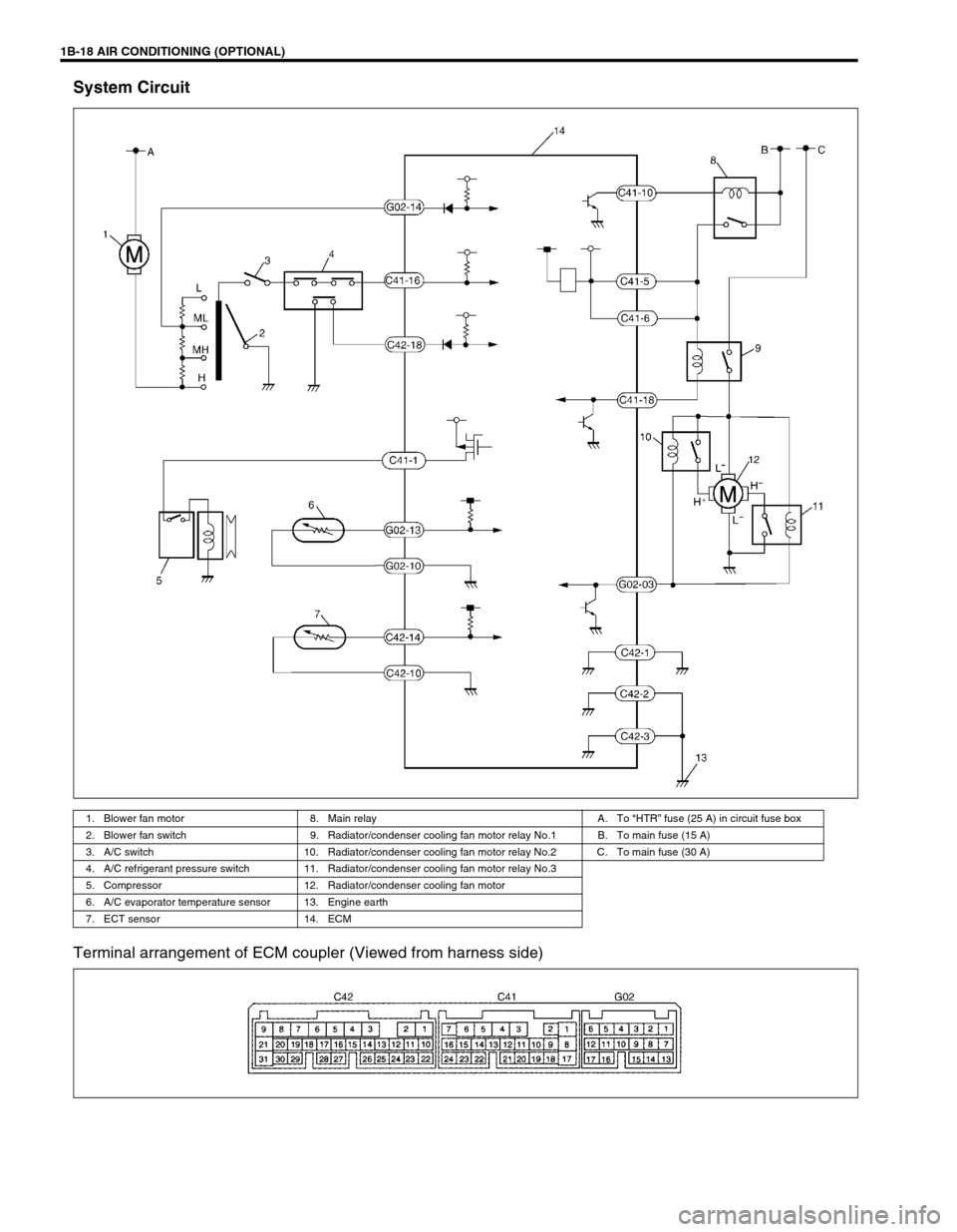
System Circuit
Terminal arrangement of ECM coupler (Viewed from harness side)
1. Blower fan motor 8. Main relay A. To “HTR” fuse (25 A) in circuit fuse box
2. Blower fan switch 9. Radiator/condenser cooling fan motor relay No.1 B. To main fuse (15 A)
3. A/C switch 10. Radiator/condenser cooling fan motor relay No.2 C. To main fuse (30 A)
4. A/C refrigerant pressure switch 11. Radiator/condenser cooling fan motor relay No.3
5. Compressor 12. Radiator/condenser cooling fan motor
6. A/C evaporator temperature sensor 13. Engine earth
7. ECT sensor 14. ECM
Page 84 of 698
AIR CONDITIONING (OPTIONAL) 1B-19
ECM Voltage Values Table for Relation of A/C Control
Terminal Wire Circuit Measurement
groundNormal value Condition
C41-1 PNK/BLK Compressor magnet
clutch outputGround to engine
(Fig B)12 – 15 V Except the above-mentioned condition with engine
running
0 – 1 V Blower fan switch and A/C switch ON with engine
running
C41-5 BLK/RED Main power supply for
ECMGround to engine
(Fig B)10 – 14 V Ignition switch ON with engine stopped
C41-6 BLK/RED Main power supply for
ECMGround to engine
(Fig B)10 – 14 V Ignition switch ON with engine stopped
C41-10 BRN/
WHTMain relay drive Ground to engine
(Fig B)0.5 – 1.2 V Ignition switch ON with engine stopped
10 – 14 V Ignition switch OFF
C41-16 YEL/GRN A/C switch input Ground to engine
(Fig B)12 – 15 V Blower fan switch or A/C switch OFF with engine
running
0 – 1 V Blower fan switch and A/C switch ON with engine
running
C41-18 BLU Radiator/condenser
cooling fan relay out-
put 1Ground to engine
(Fig B)0 – 1 V Blower fan switch and A/C switch ON
Engine coolant temperature at more than 97.5°C
(207.5°F) with engine running
12 – 15 V Blower fan motor switch or A/C switch OFF
Engine coolant temperature at less than 97.5°C
(207.5°F) with engine running
C42-1 BLK/ORN Main ground for ECM Ground to body
(Fig A)–0.5 – 1 V Engine running
C42-2 BLK ECM ground for
power circuitGround to body
(Fig A)–0.5 – 1 V Engine running
C42-3 BLK/ORN ECM ground for
power circuitGround to body
(Fig A)–0.5 – 1 V Engine running
C42-10 ORN Sensor ground for
ECT sensorGround to body
(Fig A)–0.5 – 1 V Engine running
C42-14 LT GRN/
BLKECT sensor input Ground to engine
(Fig B)0.71 – 0.75 V
(298 – 320 Ω
)Engine coolant temperature at approximately 80°C
(176°F) with engine running
0.35 – 0.37 V
(135 – 144 Ω
)Engine coolant temperature at Approximately
110°C (230°F) with engine running
If the temperature is more than 114°C (232°F),
compressor and condenser cooling fan should be
stop (come back at less than 112°C (230°F))
C42-18 PNK/GRN Medium pressure
switch inputGround to engine
(Fig B)–0.5 – 1 V Medium pressure switch of A/C refrigerant pres-
sure switch ON
12 – 15 V Medium pressure switch of A/C refrigerant pres-
sure switch OFF
G02-3 PPL/YEL Radiator/Condenser
cooling fan relay out-
put 2Ground to engine
(Fig B)0 – 1 V Blower fan motor switch ON, A/C switch ON and
medium pressure switch OFF
Engine coolant temperature at more than 102.5°C
(216.5°F) with engine running
12 – 15 V Blower fan motor switch OFF, A/C switch OFF or
medium pressure switch ON
Engine coolant temperature at less than 102.5°C
(216.5°F) with engine running
G02-10 ORN Sensor ground for A/C
evaporator tempera-
ture sensorGround to engine
(Fig A)–0.5 – 1 V Engine running
G02-13 PNK/BLU Blower fan speed
inputGround to engine
(Fig B)0 – 1 V Blower fan motor switch “ML”, “MH”, or “H” with
engine running
4 – 7 V Blower fan motor switch “L” position with engine
running
12 – 15 V Blower fan motor switch OFF with engine running
G02-14 WHT/BLK A/C evaporator tem-
perature sensor inputGround to engine
(Fig B)2.09 – 2.17 V
(1940 – 2060 Ω
)A/C evaporator temperature at approximately 25°C
(77°F) with engine running
3.52 – 3.59 V
(6450 – 6850 Ω
)A/C evaporator temperature at approximately 0°C
(32°F) with engine running
If the temperature is less than approximately 2.5°C
(36.5°F), compressor and condenser cooling fan
should be stop (come back at more than approxi-
mately 4°C (39.2°F)
Page 143 of 698
3B1-2 ELECTRICAL POWER STEERING (P/S) SYSTEM
STEERING FORCE INSPECTION ........... 3B1-28
ON-VEHICLE SERVICE ............................... 3B1-29
P/S CONTROL MODULE ......................... 3B1-29
TORQUE SENSOR .................................. 3B1-29MOTOR AND CLUTCH ............................ 3B1-30
STEERING COLUMN ASSEMBLY .......... 3B1-31
SPECIAL TOOL ........................................... 3B1-31
GENERAL DESCRIPTION
SYSTEM COMPONENTS
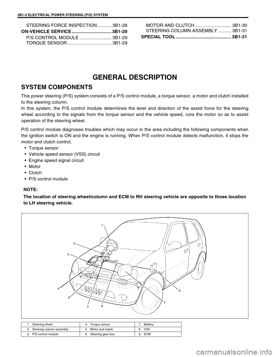
This power steering (P/S) system consists of a P/S control module, a torque sensor, a motor and clutch installed
to the steering column.
In this system, the P/S control module determines the level and direction of the assist force for the steering
wheel according to the signals from the torque sensor and the vehicle speed, runs the motor so as to assist
operation of the steering wheel.
P/S control module diagnoses troubles which may occur in the area including the following components when
the ignition switch is ON and the engine is running. When P/S control module detects malfunction, it stops the
motor and clutch control.
Torque sensor
Vehicle speed sensor (VSS) circuit
Engine speed signal circuit
Motor
Clutch
P/S control module
NOTE:
The location of steering wheel/column and ECM to RH steering vehicle are opposite to those location
to LH steering vehicle.
1. Steering wheel 4. Torque sensor 7. Battery
2. Steering column assembly 5. Motor and clutch 8. VSS
3. P/S control module 6. Steering gear box 9. ECM