remove seats SUZUKI SWIFT 2000 1.G RG413 Service Workshop Manual
[x] Cancel search | Manufacturer: SUZUKI, Model Year: 2000, Model line: SWIFT, Model: SUZUKI SWIFT 2000 1.GPages: 698, PDF Size: 16.01 MB
Page 10 of 698

GENERAL INFORMATION 0A-7
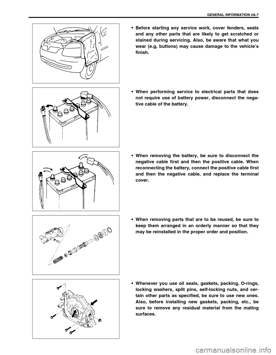
Before starting any service work, cover fenders, seats
and any other parts that are likely to get scratched or
stained during servicing. Also, be aware that what you
wear (e.g, buttons) may cause damage to the vehicle’s
finish.
When performing service to electrical parts that does
not require use of battery power, disconnect the nega-
tive cable of the battery.
When removing the battery, be sure to disconnect the
negative cable first and then the positive cable. When
reconnecting the battery, connect the positive cable first
and then the negative cable, and replace the terminal
cover.
When removing parts that are to be reused, be sure to
keep them arranged in an orderly manner so that they
may be reinstalled in the proper order and position.
Whenever you use oil seals, gaskets, packing, O-rings,
locking washers, split pins, self-locking nuts, and cer-
tain other parts as specified, be sure to use new ones.
Also, before installing new gaskets, packing, etc., be
sure to remove any residual material from the mating
surfaces.
Page 253 of 698

3F-8 WHEELS AND TIRES
TIRE
MOUNTING AND DISMOUNTING
Use a tire changing machine to mount or dismount tires. Follow equipment manufacturer’s instructions. Do not
use hand tools or tire irons alone to change tires as they may damage tire beads or wheel rim.
Rim bead seats should be cleaned with a wire brush or coarse steel wool to remove lubricants, old rubber and
light rust. Before mounting or dismounting a tire, bead area should be well lubricated with approved tire lubri-
cant.
After mounting, inflate to specified pressure shown on tire placard so that beads are completely seated.
Install valve core and inflate to proper pressure.
REPAIR
There are many different materials and techniques on the market to repair tires. As not all of these work on all
types of tires, tire manufacturers have published detailed instructions on how and when to repair tires. These
instructions can be obtained from each tire manufacturer.WARNING:
Do not stand over tire when inflating. Bead may break when bead snaps over rim’s safety hump and
cause serious personal injury.
Do not exceed specified pressure when inflating. If specified pressure will not seat beads, deflate, re-
lubricate and reinflate.
Over inflation may cause bead to break and cause serious personal injury.
Page 551 of 698

6A1-50 ENGINE MECHANICAL (M13 ENGINE)
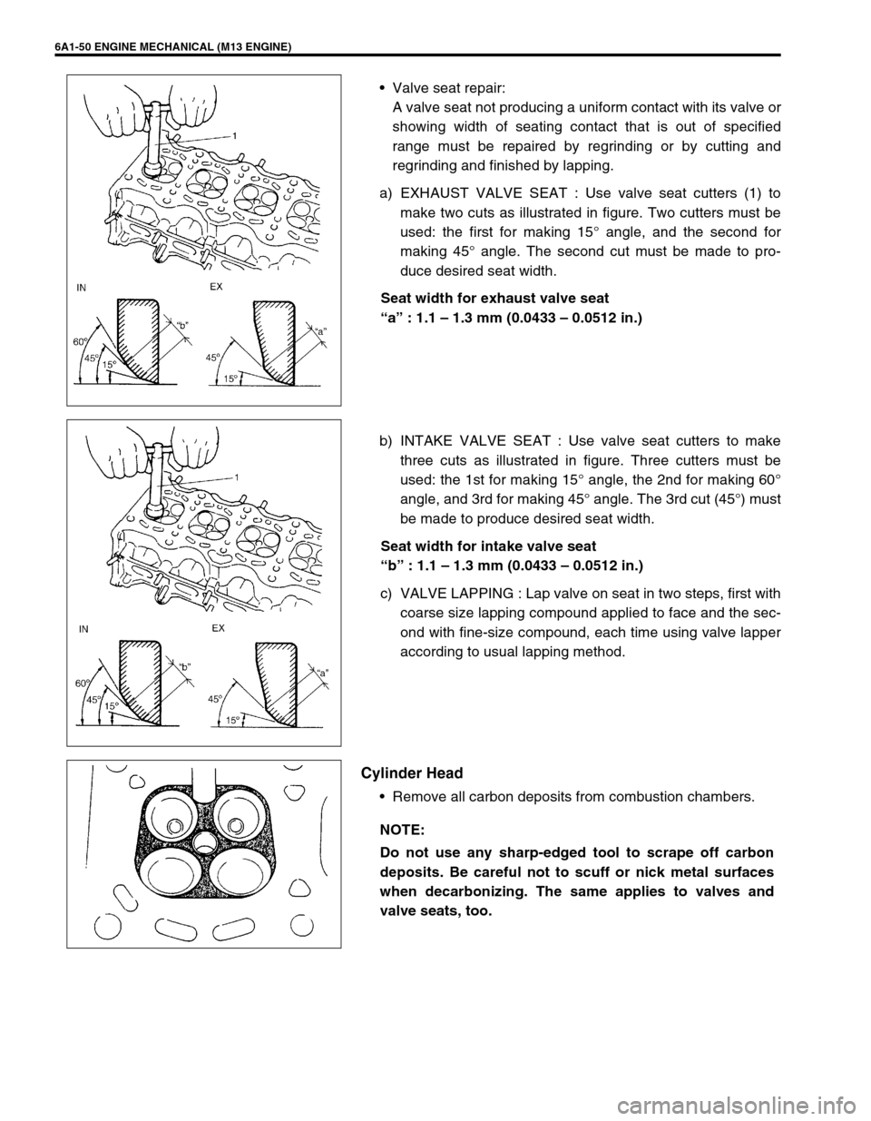
Valve seat repair:
A valve seat not producing a uniform contact with its valve or
showing width of seating contact that is out of specified
range must be repaired by regrinding or by cutting and
regrinding and finished by lapping.
a) EXHAUST VALVE SEAT : Use valve seat cutters (1) to
make two cuts as illustrated in figure. Two cutters must be
used: the first for making 15° angle, and the second for
making 45° angle. The second cut must be made to pro-
duce desired seat width.
Seat width for exhaust valve seat
“a” : 1.1 – 1.3 mm (0.0433 – 0.0512 in.)
b) INTAKE VALVE SEAT : Use valve seat cutters to make
three cuts as illustrated in figure. Three cutters must be
used: the 1st for making 15° angle, the 2nd for making 60°
angle, and 3rd for making 45° angle. The 3rd cut (45°) must
be made to produce desired seat width.
Seat width for intake valve seat
“b” : 1.1 – 1.3 mm (0.0433 – 0.0512 in.)
c) VALVE LAPPING : Lap valve on seat in two steps, first with
coarse size lapping compound applied to face and the sec-
ond with fine-size compound, each time using valve lapper
according to usual lapping method.
Cylinder Head
Remove all carbon deposits from combustion chambers.
NOTE:
Do not use any sharp-edged tool to scrape off carbon
deposits. Be careful not to scuff or nick metal surfaces
when decarbonizing. The same applies to valves and
valve seats, too.