Meter SUZUKI SWIFT 2000 1.G Transmission Service User Guide
[x] Cancel search | Manufacturer: SUZUKI, Model Year: 2000, Model line: SWIFT, Model: SUZUKI SWIFT 2000 1.GPages: 447, PDF Size: 10.54 MB
Page 121 of 447
AUTOMATIC TRANSMISSION (4 A/T) 7B-79
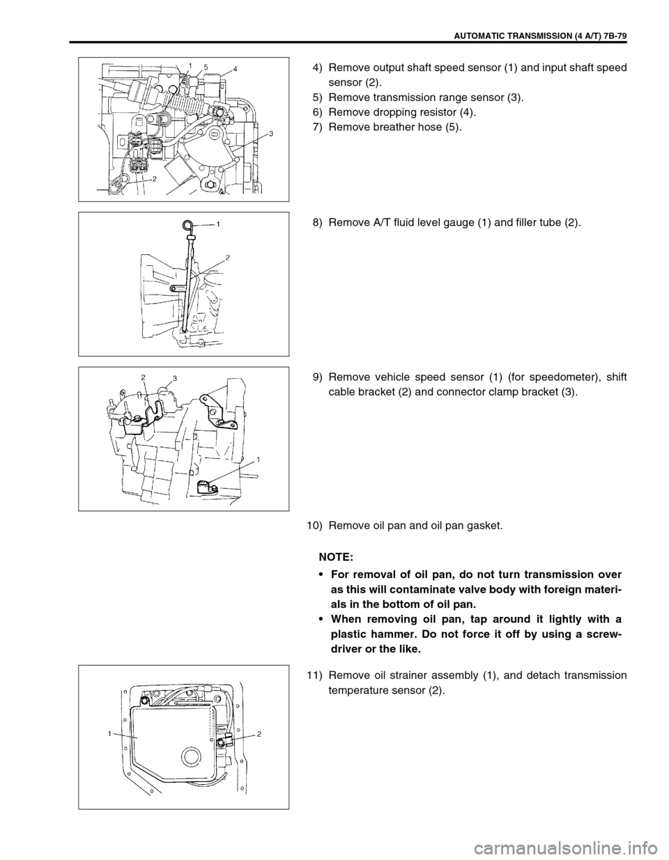
4) Remove output shaft speed sensor (1) and input shaft speed
sensor (2).
5) Remove transmission range sensor (3).
6) Remove dropping resistor (4).
7) Remove breather hose (5).
8) Remove A/T fluid level gauge (1) and filler tube (2).
9) Remove vehicle speed sensor (1) (for speedometer), shift
cable bracket (2) and connector clamp bracket (3).
10) Remove oil pan and oil pan gasket.
11) Remove oil strainer assembly (1), and detach transmission
temperature sensor (2).
NOTE:
For removal of oil pan, do not turn transmission over
as this will contaminate valve body with foreign materi-
als in the bottom of oil pan.
When removing oil pan, tap around it lightly with a
plastic hammer. Do not force it off by using a screw-
driver or the like.
Page 150 of 447

7B-108 AUTOMATIC TRANSMISSION (4 A/T)
Valve spring dimensions (Reference)
Lower Valve Body
1) Remove oil strainers (1).
2) Remove solenoid valves, if still attached.
3) Remove keys (2) and pull out all sleeve, plug, spring and
valves.
Valve spring dimensions (Reference)Spring Free length
“a” (mm)Outside diameter
“b” (mm)
Primary regula-
tor valve spring79.2 18.0
Lock-up control
valve spring31.1 8.5
Lock-up signal
valve spring36.1 8.5
3. Fail valve No.1 sleeve
4. Fail valve No.1
5. Cooler by-pass valve
6. Cooler by-pass valve spring
7. Manual valve
8. Secondary regulator valve
9. Secondary regulator valve spring
10. Secondary regulator valve plug
Spring Free length
“a” (mm)Outside diame-
ter “b” (mm)
Secondary regula-
tor valve spring38.7 8.8
Cooler by-pass
valve spring22.8 8.0
Page 154 of 447
7B-112 AUTOMATIC TRANSMISSION (4 A/T)
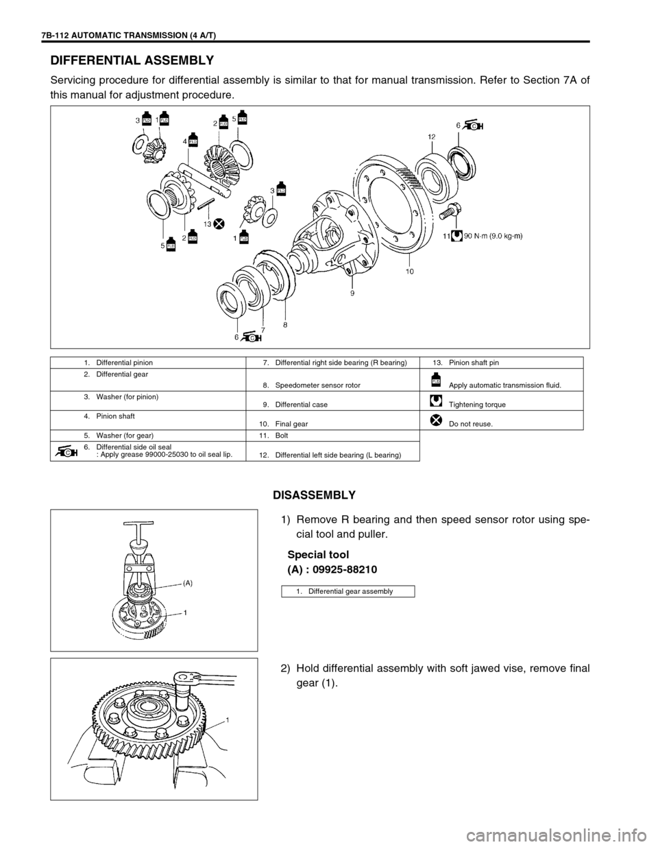
DIFFERENTIAL ASSEMBLY
Servicing procedure for differential assembly is similar to that for manual transmission. Refer to Section 7A of
this manual for adjustment procedure.
DISASSEMBLY
1) Remove R bearing and then speed sensor rotor using spe-
cial tool and puller.
Special tool
(A) : 09925-88210
2) Hold differential assembly with soft jawed vise, remove final
gear (1).
1. Differential pinion 7. Differential right side bearing (R bearing) 13. Pinion shaft pin
2. Differential gear
8. Speedometer sensor rotor Apply automatic transmission fluid.
3. Washer (for pinion)
9. Differential case Tightening torque
4. Pinion shaft
10. Final gear Do not reuse.
5. Washer (for gear) 11. Bolt
6. Differential side oil seal
: Apply grease 99000-25030 to oil seal lip.
12. Differential left side bearing (L bearing)
1. Differential gear assembly
Page 156 of 447

7B-114 AUTOMATIC TRANSMISSION (4 A/T)
5) Install differential side L bearing (1). Press-fit it by using spe-
cial tool and copper hammer.
Special tool
(D) : 09924-74510
(E) : 09926-68310
.
6) Press-fit new sensor rotor (1) with groove (2) side downward
as shown by using special tools and copper hammer.
Special tool
(F) : 09951-76010
(G) : 09940-54910
7) Support differential assembly as illustrated so as to float L
bearing, and then press-fit R bearing by using special tool
and copper hammer.
Special tool
(D) : 09924-74510
(E) : 09926-68310
(H) : 09951-16060
8) Hold differential assembly with soft jawed vise (3), install
final gear (2) and then tighten it with 8 bolts to which thread
lock cement is applied to specified torque.
Tightening torque
(a) : 90 N·m (9.0 kg-m, 65.0 lb-ft)
“A” : Thread lock cement 99000-32110
2. Differential case
1. Differential side R bearing 4. Differential case
2. Speedometer sensor rotor 5. Differential side L bearing
3. Differential pinion shaft pin
CAUTION:
Use of bolts other than specified ones is prohibited.
1. Final gear bolt
Page 176 of 447

7B-134 AUTOMATIC TRANSMISSION (4 A/T)
63) Install vehicle speed sensor (for speedometer) (1), shift
cable bracket (2) and connector clamp bracket (3).
Tightening torque
Vehicle speed sensor bolt
(a) : 5.5 N·m (0.55 kg-m, 4.0 lb-ft)
Shift cable bracket bolts
(b) : 13 N·m (1.3 kg-m, 9.5 lb-ft)
Connector clamp bracket bolt : 8 N·m (0.8 kg-m, 6.0 lb-ft)
64) Install A/T fluid filler tube (2) and level gauge (1).
Tightening torque
A/T fluid filler tube bolt (a) : 19.5 N·m (1.95 kg-m, 14.5 lb-ft)
65) Install output shaft speed sensor (1) and input shaft speed
sensor (2).
Apply grease to O-ring of each sensor.
Tightening torque
Output shaft speed sensor bolt
(a) : 8 N·m (0.8 kg-m, 6.0 lb-ft)
Input shaft speed sensor bolt
(b) : 8 N·m (0.8 kg-m, 6.0 Ib-ft)
Grease : 99000-25030
66) Install engine mounting LH bracket.
Tightening torque
Engine mounting LH bracket bolts
(a) : 55 N·m (5.5 kg-m, 40.0 lb-ft)
Page 184 of 447
7C-2 CLUTCH
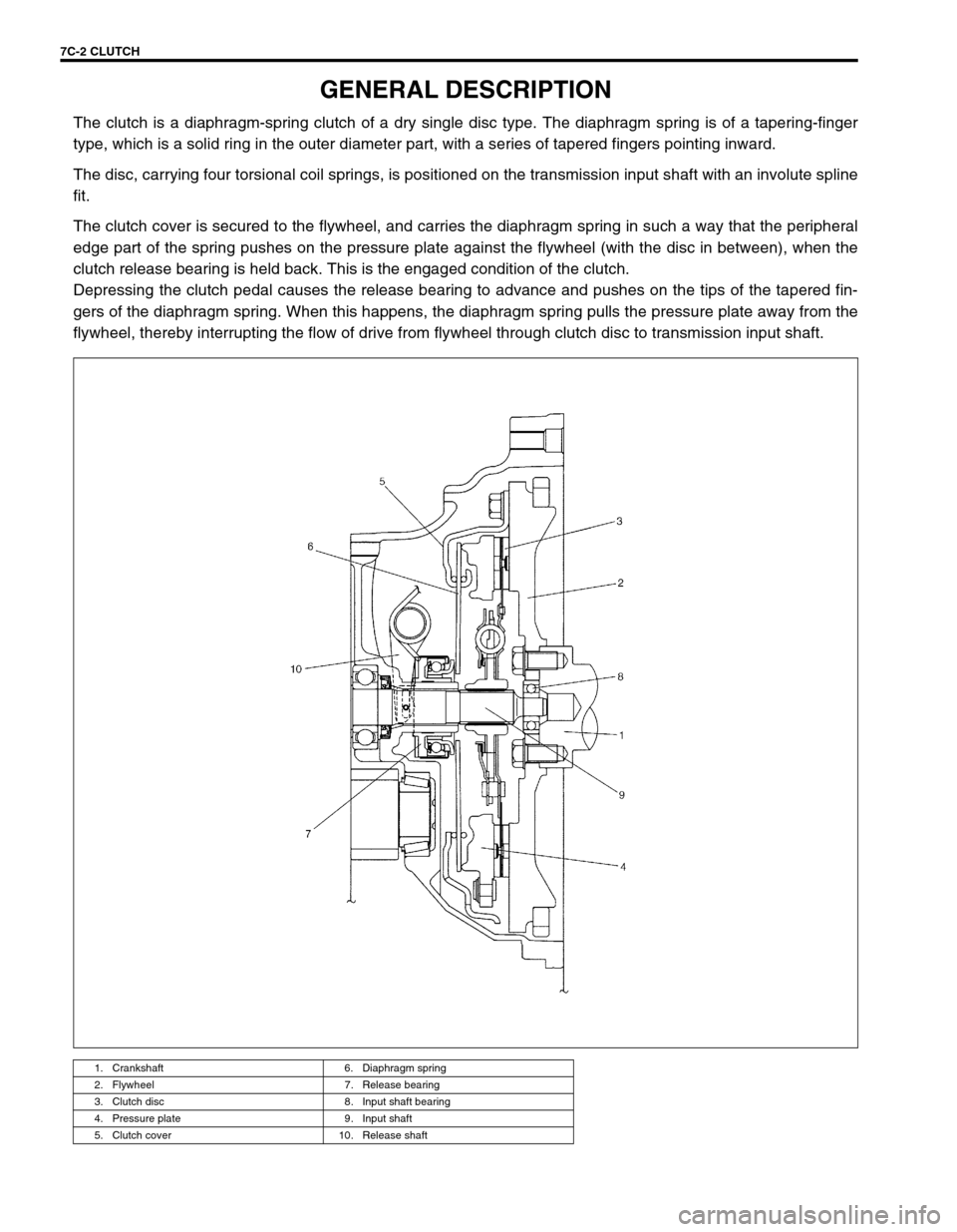
GENERAL DESCRIPTION
The clutch is a diaphragm-spring clutch of a dry single disc type. The diaphragm spring is of a tapering-finger
type, which is a solid ring in the outer diameter part, with a series of tapered fingers pointing inward.
The disc, carrying four torsional coil springs, is positioned on the transmission input shaft with an involute spline
fit.
The clutch cover is secured to the flywheel, and carries the diaphragm spring in such a way that the peripheral
edge part of the spring pushes on the pressure plate against the flywheel (with the disc in between), when the
clutch release bearing is held back. This is the engaged condition of the clutch.
Depressing the clutch pedal causes the release bearing to advance and pushes on the tips of the tapered fin-
gers of the diaphragm spring. When this happens, the diaphragm spring pulls the pressure plate away from the
flywheel, thereby interrupting the flow of drive from flywheel through clutch disc to transmission input shaft.
1. Crankshaft 6. Diaphragm spring
2. Flywheel 7. Release bearing
3. Clutch disc 8. Input shaft bearing
4. Pressure plate 9. Input shaft
5. Clutch cover 10. Release shaft
Page 210 of 447
7D-12 TRANSFER
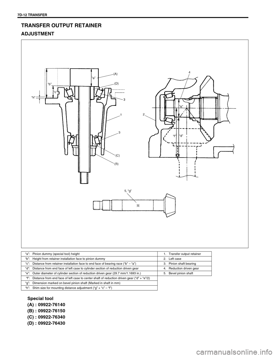
TRANSFER OUTPUT RETAINER
ADJUSTMENT
Special tool
(A) : 09922-76140
(B) : 09922-76150
(C) : 09922-76340
(D) : 09922-76430
“a”: Pinion dummy (special tool) height 1. Transfer output retainer
“b”: Height from retainer installation face to pinion dummy 2. Left case
“c”: Distance from retainer installation face to end face of bearing race (“b” – “a”) 3. Pinion shaft bearing
“d”: Distance from end face of left case to cylinder section of reduction driven gear 4. Reduction driven gear
“e”: Outer diameter of cylinder section of reduction driven gear (29.7 mm/1.1693 in.) 5. Bevel pinion shaft
“f”: Distance from end face of left case to center shaft of reduction driven gear (“d” + “e”/2)
“g”: Dimension marked on bevel pinion shaft (Marked in shaft in mm)
“h”: Shim size for mounting distance adjustment (“g” + “c” – “f”)
Page 215 of 447
TRANSFER 7D-17
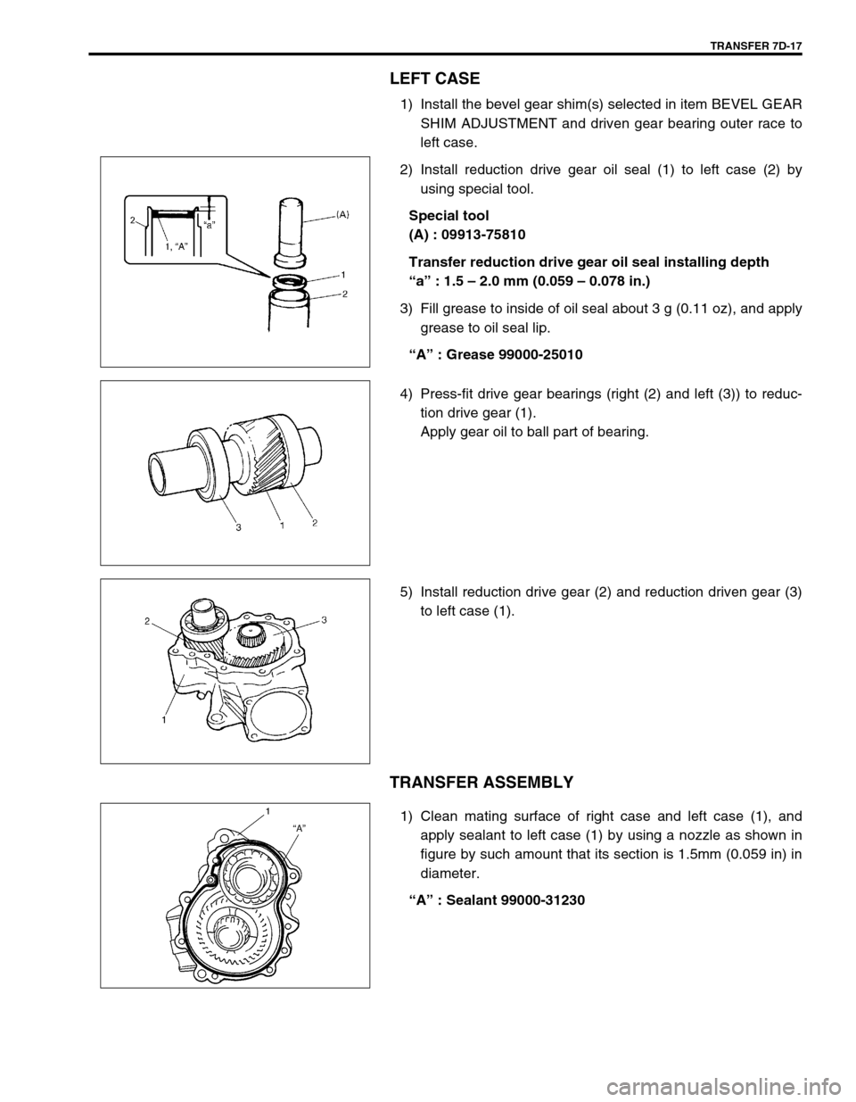
LEFT CASE
1) Install the bevel gear shim(s) selected in item BEVEL GEAR
SHIM ADJUSTMENT and driven gear bearing outer race to
left case.
2) Install reduction drive gear oil seal (1) to left case (2) by
using special tool.
Special tool
(A) : 09913-75810
Transfer reduction drive gear oil seal installing depth
“a” : 1.5 – 2.0 mm (0.059 – 0.078 in.)
3) Fill grease to inside of oil seal about 3 g (0.11 oz), and apply
grease to oil seal lip.
“A” : Grease 99000-25010
4) Press-fit drive gear bearings (right (2) and left (3)) to reduc-
tion drive gear (1).
Apply gear oil to ball part of bearing.
5) Install reduction drive gear (2) and reduction driven gear (3)
to left case (1).
TRANSFER ASSEMBLY
1) Clean mating surface of right case and left case (1), and
apply sealant to left case (1) by using a nozzle as shown in
figure by such amount that its section is 1.5mm (0.059 in) in
diameter.
“A” : Sealant 99000-31230
Page 242 of 447

7F-20 REAR DIFFERENTIAL
UNIT ASSEMBLY
Before installing viscous coupling case (1) to differential carrier
(2), clean mating surfaces of viscous coupling case and differen-
tial carrier, then apply sealant to differential carrier (2) by using a
nozzle as shown in figure by such amount that its section is
1.5mm (0.059 in.) in diameter.
“A” : Sealant 99000-31110
Tightening torque
Coupling case bolts (a) : 25 N·m (2.5 kg-m, 18.0 lb-ft)
TIGHTENING TORQUE SPECIFICATION
Irregular patterns: If the pattern is not oval, it means
that bevel gear is defective. High or low spots on tooth
surfaces or on the seat of bevel gear are the cause of
irregular patterns appearing on some teeth. The rem-
edy is to replace the pinion and-gear set and, if the
seat is defective, so is transfer case. TOOTH CONTACT PATTERN DIAGNOSIS AND REMEDY
Fastening partTightening torque
Nm kg-m lb-ft
Rear differential oil drain plug 55 5.5 40.0
Rear differential oil level/filler plug 50 5.0 36.5
Rear differential companion flange nut 130 13.0 94.0
Rear differential input flange bolts 23 2.3 17.0
Drive bevel gear bolts 80 8.0 58.0
Differential side bearing cap bolts 23 2.3 17.0
Coupling case bolts 25 2.5 18.0
Differential carrier bolts 23 2.3 17.0
Propeller shaft bolts 23 2.3 17.0
Page 245 of 447
BODY ELECTRICAL SYSTEM 8-1
6F1
6F2
6G
6H
6K
7A
7A1
7B1
7C1
7D
7E
7F
8A
8
8D
8E
9
10
10A
10B
SECTION 8
BODY ELECTRICAL SYSTEM
CONTENTS
DIAGNOSIS ........................................................ 8-3
HEADLIGHT .................................................... 8-3
HEADLIGHTS WITH LEVELING SYSTEM
(IF EQUIPPED) ............................................... 8-3
TURN SIGNAL AND HAZARD WARNING
LIGHT .............................................................. 8-3
CLEARANCE, TAIL AND LICENSE
PLATE LIGHT ................................................. 8-4
BACK-UP LIGHT ............................................. 8-4
BRAKE LIGHT ................................................ 8-4
FRONT FOG LIGHT (IF EQUIPPED) ............. 8-4
REAR FOG LIGHT (IF EQUIPPED) ................ 8-4
SPEEDOMETER AND VSS ............................ 8-5
FUEL METER AND FUEL LEVEL SENSOR
(GAUGE UNIT) ............................................... 8-5
ENGINE COOLANT TEMPERATURE (ECT)
METER AND ECT SENSOR ........................... 8-5
OIL PRESSURE WARNING LIGHT ................ 8-5
BRAKE AND PARKING BRAKE WARNING
LIGHT .............................................................. 8-6
REAR WINDOW DEFOGGER ........................ 8-6
WIPERS AND WASHERS .............................. 8-6
FRONT WIPER AND WASHER .................. 8-6
REAR WIPER AND WASHER (IF
EQUIPPED)................................................. 8-6
POWER WINDOW CONTROL SYSTEM
(IF EQUIPPED) ............................................... 8-7
CIGARETTE LIGHTER ................................... 8-7
POWER DOOR LOCK CONTROL SYSTEM
(IF EQUIPPED) ............................................... 8-7
KEYLESS ENTRY SYSTEM (IF
EQUIPPED) .................................................... 8-7POWER DOOR MIRROR CONTROL
SYSTEM (IF EQUIPPED) ............................... 8-8
INTERIOR LIGHT ........................................... 8-8
HORN ............................................................. 8-8
IGNITION KEY REMAINDER (IF EQUIPPED)
AND LIGHT REMAINDER WARNING
BUZZER.......................................................... 8-8
SEAT BELT WARNING LIGHT (IF
EQUIPPED) .................................................... 8-8
FRONT SEAT HEATER (IF EQUIPPED) ....... 8-9
ON-VEHICLE SERVICE ..................................... 8-9
CAUTIONS IN SERVICING ............................ 8-9
HEADLIGHT ................................................... 8-9
HEADLIGHT SWITCH ................................ 8-9
HEADLIGHT ASSEMBLY ......................... 8-10
HEADLIGHT BULB ................................... 8-10
HEADLIGHT AIMING ADJUSTMENT
WITH SCREEN ......................................... 8-11
HEADLIGHT LEVELING SWITCH (IF
EQUIPPED) .............................................. 8-12
TURN SIGNAL AND HAZARD WARNING
LIGHTS ......................................................... 8-12
TURN SIGNAL LIGHT SWITCH ............... 8-12
REMOVAL AND INSTALLATION ............. 8-12
TURN SIGNAL AND HAZARD RELAY ..... 8-13
HAZARD SWITCH .................................... 8-13
FRONT FOG LIGHTS (IF EQUIPPED)......... 8-13
FRONT FOG LIGHT SWITCH .................. 8-13
REAR FOG LIGHT (IF EQUIPPED) ............. 8-14
REAR FOG LIGHT SWITCH..................... 8-14
IGNITION SWITCH ....................................... 8-14
COMBINATION METER ............................... 8-15 WARNING:
For vehicles equipped with Supplemental Restraint (Air Bag) System :
Service on and around the air bag system components or wiring must be performed only by an
authorized SUZUKI dealer. Refer to “Air Bag System Components and Wiring Location View” under
“General Description” in air bag system section in order to confirm whether you are performing ser-
vice on or near the air bag system components or wiring. Please observe all WARNINGS and “Ser-
vice Precautions” under “On-Vehicle Service” in air bag system section before performing service
on or around the air bag system components or wiring. Failure to follow WARNINGS could result in
unintentional activation of the system or could render the system inoperative. Either of these two
conditions may result in severe injury.
Technical service work must be started at least 90 seconds after the ignition switch is turned to the
“LOCK” position and the negative cable is disconnected from the battery. Otherwise, the system
may be activated by reserve energy in the Sensing and Diagnostic Module (SDM).