Meter SUZUKI SWIFT 2000 1.G Transmission Service Owner's Manual
[x] Cancel search | Manufacturer: SUZUKI, Model Year: 2000, Model line: SWIFT, Model: SUZUKI SWIFT 2000 1.GPages: 447, PDF Size: 10.54 MB
Page 246 of 447
8-2 BODY ELECTRICAL SYSTEM
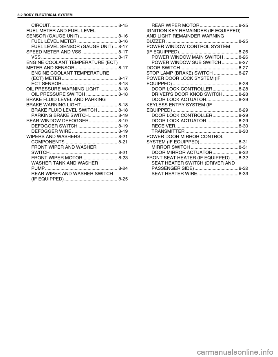
CIRCUIT.................................................... 8-15
FUEL METER AND FUEL LEVEL
SENSOR (GAUGE UNIT) ............................. 8-16
FUEL LEVEL METER ............................... 8-16
FUEL LEVEL SENSOR (GAUGE UNIT) ... 8-17
SPEED METER AND VSS ........................... 8-17
VSS ........................................................... 8-17
ENGINE COOLANT TEMPERATURE (ECT)
METER AND SENSOR................................. 8-17
ENGINE COOLANT TEMPERATURE
(ECT) METER ........................................... 8-17
ECT SENSOR ........................................... 8-18
OIL PRESSURE WARNING LIGHT ............. 8-18
OIL PRESSURE SWITCH ........................ 8-18
BRAKE FLUID LEVEL AND PARKING
BRAKE WARNING LIGHT ............................ 8-18
BRAKE FLUID LEVEL SWITCH ............... 8-18
PARKING BRAKE SWITCH...................... 8-19
REAR WINDOW DEFOGGER...................... 8-19
DEFOGGER SWITCH .............................. 8-19
DEFOGGER WIRE ................................... 8-19
WIPERS AND WASHERS ............................ 8-21
COMPONENTS ........................................ 8-21
FRONT WIPER AND WASHER
SWITCH .................................................... 8-21
FRONT WIPER MOTOR........................... 8-23
WASHER TANK AND WASHER
PUMP ........................................................ 8-24
REAR WIPER AND WASHER SWITCH
(IF EQUIPPED) ......................................... 8-25REAR WIPER MOTOR .............................. 8-25
IGNITION KEY REMAINDER (IF EQUIPPED)
AND LIGHT REMAINDER WARNING
BUZZER ........................................................ 8-25
POWER WINDOW CONTROL SYSTEM
(IF EQUIPPED).............................................. 8-26
POWER WINDOW MAIN SWITCH ........... 8-26
POWER WINDOW SUB SWITCH ............. 8-27
DOOR SWITCH ............................................. 8-27
STOP LAMP (BRAKE) SWITCH ................... 8-27
POWER DOOR LOCK SYSTEM (IF
EQUIPPED) ................................................... 8-28
DOOR LOCK CONTROLLER .................... 8-28
DRIVER’S DOOR KNOB SWITCH ............ 8-28
DOOR LOCK ACTUATOR......................... 8-29
KEYLESS ENTRY SYSTEM (IF
EQUIPPED) ................................................... 8-29
DOOR LOCK CONTROLLER .................... 8-29
DOOR LOCK ACTUATOR......................... 8-29
RECEIVER................................................. 8-30
TRANSMITTER ......................................... 8-30
POWER DOOR MIRROR CONTROL
SYSTEM (IF EQUIPPED) .............................. 8-31
MIRROR SWITCH ..................................... 8-31
DOOR MIRROR ACTUATOR .................... 8-32
FRONT SEAT HEATER (IF EQUIPPED) ...... 8-32
SEAT HEATER SWITCH (DRIVER AND
PASSENGER SIDE) .................................. 8-32
SEAT HEATER WIRE................................ 8-33
Page 249 of 447
BODY ELECTRICAL SYSTEM 8-5
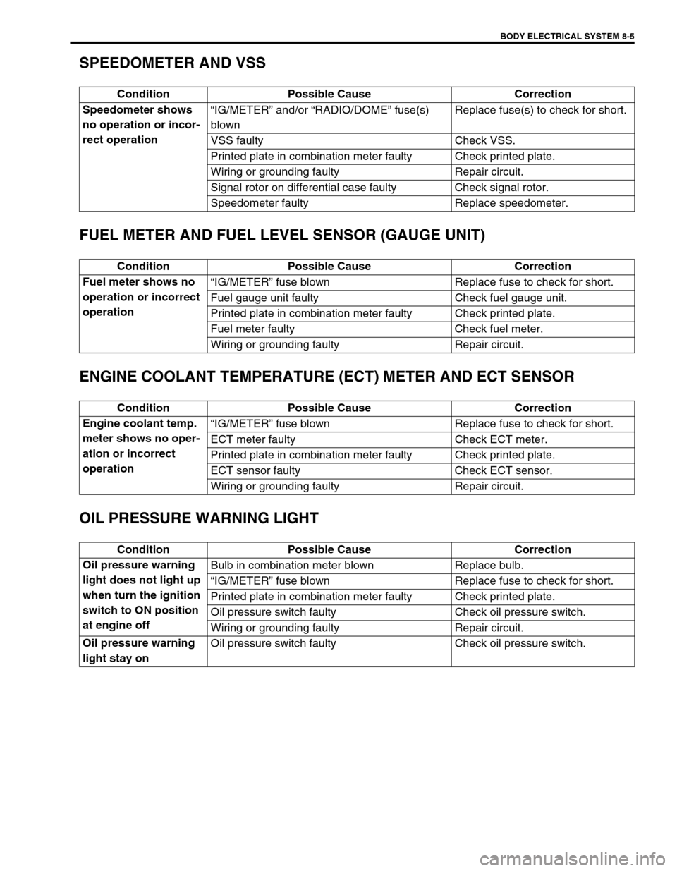
SPEEDOMETER AND VSS
FUEL METER AND FUEL LEVEL SENSOR (GAUGE UNIT)
ENGINE COOLANT TEMPERATURE (ECT) METER AND ECT SENSOR
OIL PRESSURE WARNING LIGHT
Condition Possible Cause Correction
Speedometer shows
no operation or incor-
rect operation“IG/METER” and/or “RADIO/DOME” fuse(s)
blownReplace fuse(s) to check for short.
VSS faulty Check VSS.
Printed plate in combination meter faulty Check printed plate.
Wiring or grounding faulty Repair circuit.
Signal rotor on differential case faulty Check signal rotor.
Speedometer faulty Replace speedometer.
Condition Possible Cause Correction
Fuel meter shows no
operation or incorrect
operation“IG/METER” fuse blown Replace fuse to check for short.
Fuel gauge unit faulty Check fuel gauge unit.
Printed plate in combination meter faulty Check printed plate.
Fuel meter faulty Check fuel meter.
Wiring or grounding faulty Repair circuit.
Condition Possible Cause Correction
Engine coolant temp.
meter shows no oper-
ation or incorrect
operation“IG/METER” fuse blown Replace fuse to check for short.
ECT meter faulty Check ECT meter.
Printed plate in combination meter faulty Check printed plate.
ECT sensor faulty Check ECT sensor.
Wiring or grounding faulty Repair circuit.
Condition Possible Cause Correction
Oil pressure warning
light does not light up
when turn the ignition
switch to ON position
at engine offBulb in combination meter blown Replace bulb.
“IG/METER” fuse blown Replace fuse to check for short.
Printed plate in combination meter faulty Check printed plate.
Oil pressure switch faulty Check oil pressure switch.
Wiring or grounding faulty Repair circuit.
Oil pressure warning
light stay onOil pressure switch faulty Check oil pressure switch.
Page 250 of 447
8-6 BODY ELECTRICAL SYSTEM
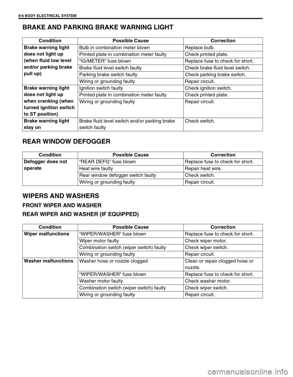
BRAKE AND PARKING BRAKE WARNING LIGHT
REAR WINDOW DEFOGGER
WIPERS AND WASHERS
FRONT WIPER AND WASHER
REAR WIPER AND WASHER (IF EQUIPPED)
Condition Possible Cause Correction
Brake warning light
does not light up
(when fluid low level
and/or parking brake
pull up)Bulb in combination meter blown Replace bulb.
Printed plate in combination meter faulty Check printed plate.
“IG/METER” fuse blown Replace fuse to check for short.
Brake fluid level switch faulty Check brake fluid level switch.
Parking brake switch faulty Check parking brake switch.
Wiring or grounding faulty Repair circuit.
Brake warning light
does not light up
when cranking (when
turned ignition switch
to ST position)Ignition switch faulty Check ignition switch.
Printed plate in combination meter faulty Check printed plate.
Wiring or grounding faulty Repair circuit.
Brake warning light
stay onBrake fluid level switch and/or parking brake
switch faultyCheck switch.
Condition Possible Cause Correction
Defogger does not
operate“REAR DEFG” fuse blown Replace fuse to check for short.
Heat wire faulty Repair heat wire.
Rear window defogger switch faulty Check switch.
Wiring or grounding faulty Repair circuit.
Condition Possible Cause Correction
Wiper malfunctions
“WIPER/WASHER” fuse blown Replace fuse to check for short.
Wiper motor faulty Check wiper motor.
Combination switch (wiper switch) faulty Check wiper switch.
Wiring or grounding faulty Repair circuit.
Washer malfunctions
Washer hose or nozzle clogged Clean or repair clogged hose or
nozzle.
“WIPER/WASHER” fuse blown Replace fuse to check for short.
Washer motor faulty Check washer motor.
Combination switch (wiper switch) faulty Check wiper switch.
Wiring or grounding faulty Repair circuit.
Page 252 of 447
8-8 BODY ELECTRICAL SYSTEM
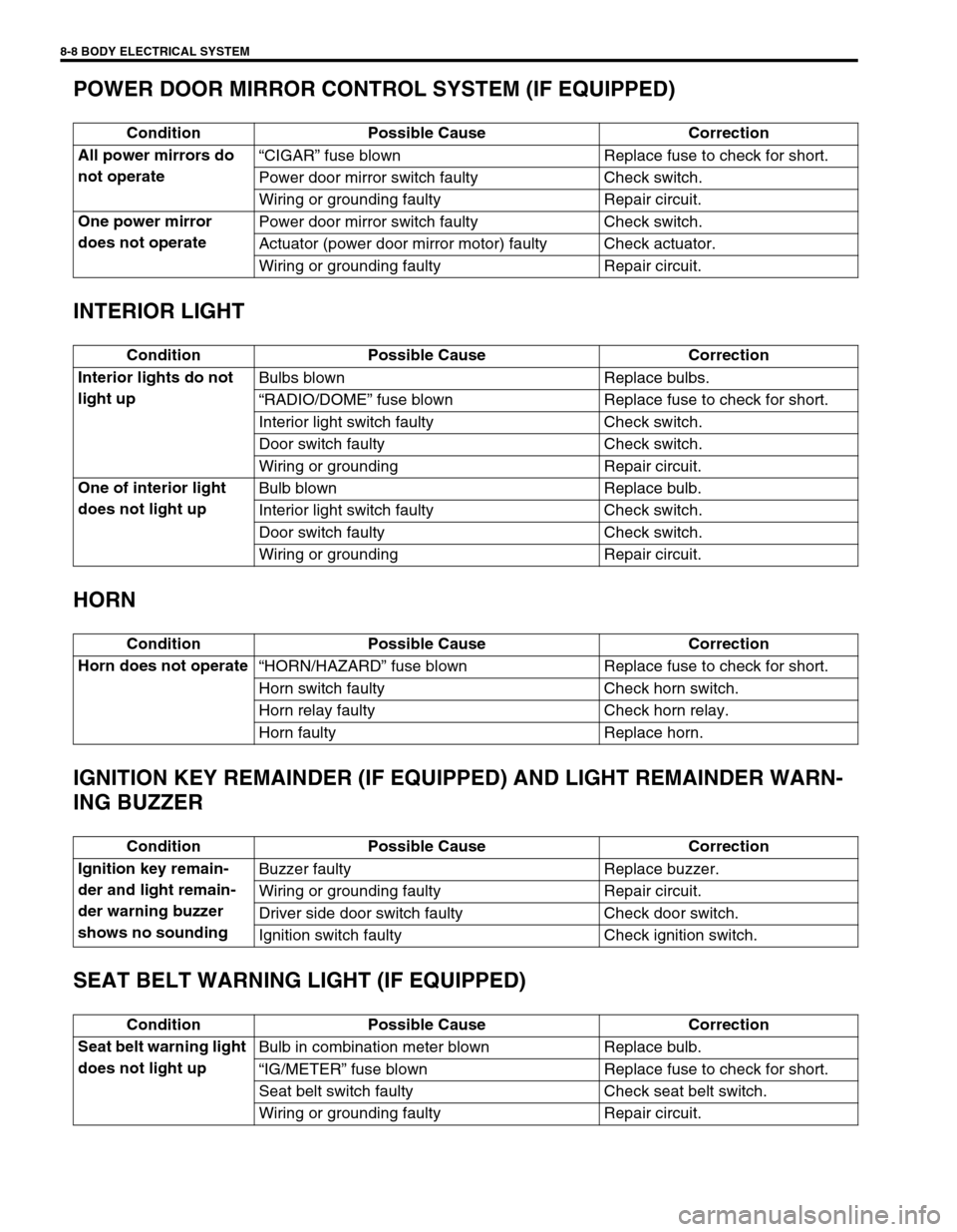
POWER DOOR MIRROR CONTROL SYSTEM (IF EQUIPPED)
INTERIOR LIGHT
HORN
IGNITION KEY REMAINDER (IF EQUIPPED) AND LIGHT REMAINDER WARN-
ING BUZZER
SEAT BELT WARNING LIGHT (IF EQUIPPED)
Condition Possible Cause Correction
All power mirrors do
not operate“CIGAR” fuse blown Replace fuse to check for short.
Power door mirror switch faulty Check switch.
Wiring or grounding faulty Repair circuit.
One power mirror
does not operatePower door mirror switch faulty Check switch.
Actuator (power door mirror motor) faulty Check actuator.
Wiring or grounding faulty Repair circuit.
Condition Possible Cause Correction
Interior lights do not
light upBulbs blown Replace bulbs.
“RADIO/DOME” fuse blown Replace fuse to check for short.
Interior light switch faulty Check switch.
Door switch faulty Check switch.
Wiring or grounding Repair circuit.
One of interior light
does not light upBulb blown Replace bulb.
Interior light switch faulty Check switch.
Door switch faulty Check switch.
Wiring or grounding Repair circuit.
Condition Possible Cause Correction
Horn does not operate
“HORN/HAZARD” fuse blown Replace fuse to check for short.
Horn switch faulty Check horn switch.
Horn relay faulty Check horn relay.
Horn faulty Replace horn.
Condition Possible Cause Correction
Ignition key remain-
der and light remain-
der warning buzzer
shows no soundingBuzzer faulty Replace buzzer.
Wiring or grounding faulty Repair circuit.
Driver side door switch faulty Check door switch.
Ignition switch faulty Check ignition switch.
Condition Possible Cause Correction
Seat belt warning light
does not light upBulb in combination meter blown Replace bulb.
“IG/METER” fuse blown Replace fuse to check for short.
Seat belt switch faulty Check seat belt switch.
Wiring or grounding faulty Repair circuit.
Page 259 of 447
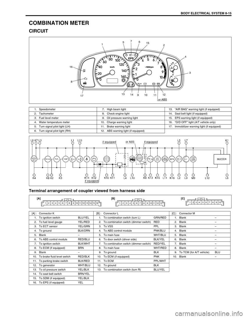
BODY ELECTRICAL SYSTEM 8-15
COMBINATION METER
CIRCUIT
Terminal arrangement of coupler viewed from harness side
12
3 4
56 7
8
910
1112 13
14
1715
16
or ABS
1. Speedometer 7. High beam light 13.“AIR BAG” warning light (if equipped)
2. Tachometer 8. Check engine light 14. Seat belt light (if equipped)
3. Fuel level meter 9. Oil pressure warning light 15. EPS warning light (if equipped)
4. Water temperature meter 10. Charge warning light 16.“O/D OFF” light (A/T vehicle only)
5. Turn signal pilot light (LH) 11. Brake warning light 17. Immobilizer warning light (if equipped)
6. Turn signal pilot light (RH) 12. ABS warning light (if equipped)
[A] : Connector K [B] : Connector L [C] : Connector M
1. To ignition switch BLU/YEL 1. To combination switch (turn L) GRN/RED 1. Blank–
2. To fuel level gauge YEL/RED 2. To combination switch (dimmer switch) RED 2. Blank–
3. To ECT sensor YEL/GRN 3. To VSS PPL 3. Blank–
4. To ground BLK/ORN 4. To ABS control module PNK/BLU 4. Blank–
5. Blank–5. To main fuse WHT/BLU 5. Blank–
6. To ABS control module RED/BLU 6. To door switch (driver side) BLK/YEL 6. Blank–
7. To ignition switch BLK/WHT 7. To combination switch (dimmer switch) RED/YEL 7. Blank–
8. To ECM (if equipped) BRN 8. To main fuse WHT/RED 8. Blank–
9. Blank–9. To ground BLK 9. To TCM (for A/T vehicle) BLU
10. To brake fluid level switch RED/BLK 10. To ECM (if equipped) PNK 10. Blank–
11. To parking brake switch BLK/RED 11. To ECM PPL/WHT
12. To generator WHT/BLU 12. To ground BLK
13. To oil pressure switch YEL/BLK 13. To combination switch (turn R) BLU/YEL
14. To seat belt switch BRN/YEL
15. To SDM (if equipped) YEL/BLK
16. To EPS (if equipped) YEL
1 2 3 4 5 6 7 8 9 10 11 12 13 14 15 161 2 3 4 5 6 7 8 9 10 11 12 131234 567 8910[A] [B] [C]
Page 260 of 447
8-16 BODY ELECTRICAL SYSTEM
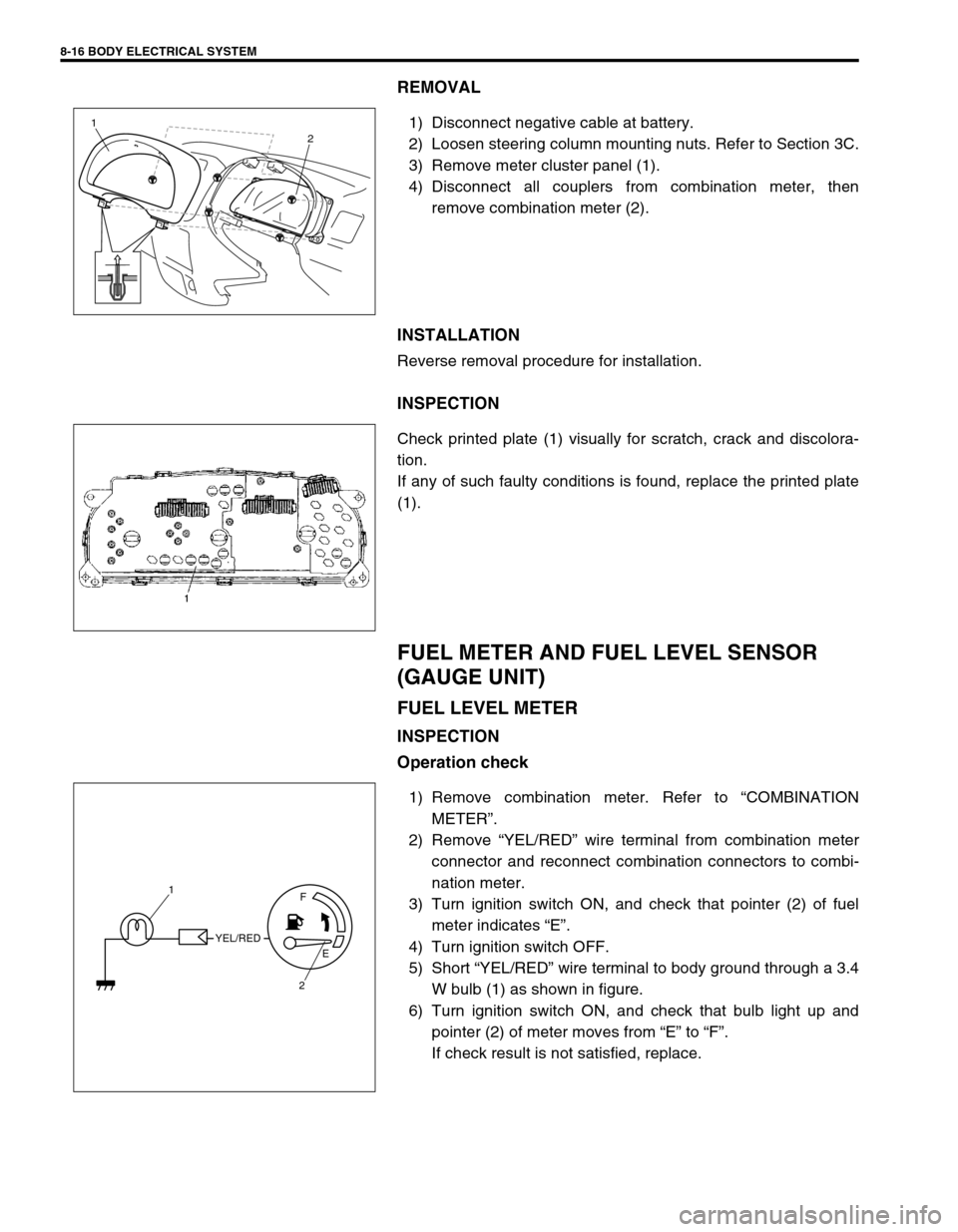
REMOVAL
1) Disconnect negative cable at battery.
2) Loosen steering column mounting nuts. Refer to Section 3C.
3) Remove meter cluster panel (1).
4) Disconnect all couplers from combination meter, then
remove combination meter (2).
INSTALLATION
Reverse removal procedure for installation.
INSPECTION
Check printed plate (1) visually for scratch, crack and discolora-
tion.
If any of such faulty conditions is found, replace the printed plate
(1).
FUEL METER AND FUEL LEVEL SENSOR
(GAUGE UNIT)
FUEL LEVEL METER
INSPECTION
Operation check
1) Remove combination meter. Refer to “COMBINATION
METER”.
2) Remove “YEL/RED” wire terminal from combination meter
connector and reconnect combination connectors to combi-
nation meter.
3) Turn ignition switch ON, and check that pointer (2) of fuel
meter indicates “E”.
4) Turn ignition switch OFF.
5) Short “YEL/RED” wire terminal to body ground through a 3.4
W bulb (1) as shown in figure.
6) Turn ignition switch ON, and check that bulb light up and
pointer (2) of meter moves from “E” to “F”.
If check result is not satisfied, replace.
1
2
YEL/REDF
E
2 1
Page 261 of 447
BODY ELECTRICAL SYSTEM 8-17
FUEL LEVEL SENSOR (GAUGE UNIT)
REMOVAL
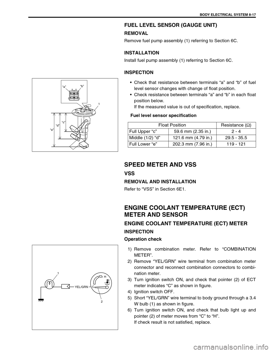
Remove fuel pump assembly (1) referring to Section 6C.
INSTALLATION
Install fuel pump assembly (1) referring to Section 6C.
INSPECTION
Check that resistance between terminals “a” and “b” of fuel
level sensor changes with change of float position.
Check resistance between terminals “a” and “b” in each float
position below.
If the measured value is out of specification, replace.
Fuel level sensor specification
SPEED METER AND VSS
VSS
REMOVAL AND INSTALLATION
Refer to “VSS” in Section 6E1.
ENGINE COOLANT TEMPERATURE (ECT)
METER AND SENSOR
ENGINE COOLANT TEMPERATURE (ECT) METER
INSPECTION
Operation check
1) Remove combination meter. Refer to “COMBINATION
METER”.
2) Remove “YEL/GRN” wire terminal from combination meter
connector and reconnect combination connectors to combi-
nation meter.
3) Turn ignition switch ON, and check that pointer (2) of ECT
meter indicates “C” as shown in figure.
4) Ignition switch OFF.
5) Short “YEL/GRN” wire terminal to body ground through a 3.4
W bulb (1) as shown in figure.
6) Turn ignition switch ON, and check that bulb light up and
pointer (2) of meter moves from “C” to “H”.
If check result is not satisfied, replace.Float Position Resistance (Ω
)
Full Upper “c”59.6 mm (2.35 in.) 2 - 4
Middle (1/2) “d”121.6 mm (4.79 in.) 29.5 - 35.5
Full Lower “e”202.3 mm (7.96 in.) 119 - 121
“a”“b”
1
“c”
“d”
“e”
YEL/GRNC
H1
2
Page 264 of 447
8-20 BODY ELECTRICAL SYSTEM
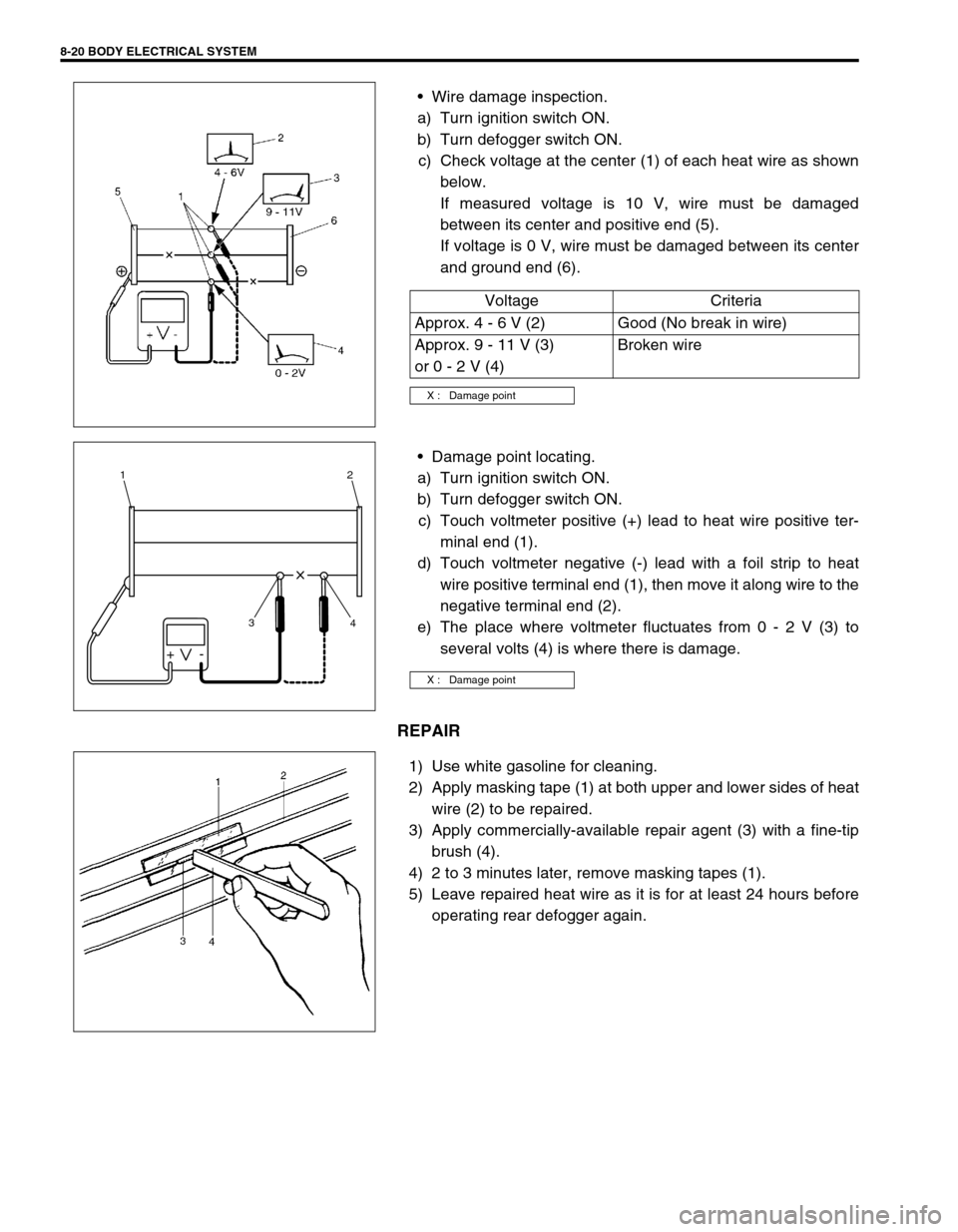
Wire damage inspection.
a) Turn ignition switch ON.
b) Turn defogger switch ON.
c) Check voltage at the center (1) of each heat wire as shown
below.
If measured voltage is 10 V, wire must be damaged
between its center and positive end (5).
If voltage is 0 V, wire must be damaged between its center
and ground end (6).
Damage point locating.
a) Turn ignition switch ON.
b) Turn defogger switch ON.
c) Touch voltmeter positive (+) lead to heat wire positive ter-
minal end (1).
d) Touch voltmeter negative (-) lead with a foil strip to heat
wire positive terminal end (1), then move it along wire to the
negative terminal end (2).
e) The place where voltmeter fluctuates from 0 - 2 V (3) to
several volts (4) is where there is damage.
REPAIR
1) Use white gasoline for cleaning.
2) Apply masking tape (1) at both upper and lower sides of heat
wire (2) to be repaired.
3) Apply commercially-available repair agent (3) with a fine-tip
brush (4).
4) 2 to 3 minutes later, remove masking tapes (1).
5) Leave repaired heat wire as it is for at least 24 hours before
operating rear defogger again.Voltage Criteria
Approx. 4 - 6 V (2) Good (No break in wire)
Approx. 9 - 11 V (3)
or 0 - 2 V (4)Broken wire
X : Damage point
X : Damage point
+-
3 12
4
Page 266 of 447
8-22 BODY ELECTRICAL SYSTEM
INSPECTION
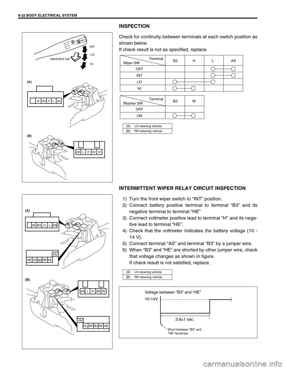
Check for continuity between terminals at each switch position as
shown below.
If check result is not as specified, replace.
INTERMITTENT WIPER RELAY CIRCUIT INSPECTION
1) Turn the front wiper switch to “INT” position.
2) Connect battery positive terminal to terminal “B3” and its
negative terminal to terminal “HE”
3) Connect voltmeter positive lead to terminal “H” and its nega-
tive lead to terminal “HE”.
4) Check that the voltmeter indicates the battery voltage (10 -
14 V).
5) Connect terminal “AS” and terminal “B3” by a jumper wire.
6) When “B3” and “HE” are shorted by other jumper wire, check
that voltage changes as shown in figure.
If check result is not satisfied, replace.
[A] : LH steering vehicle
[B] : RH steering vehicle
INT
WASHER ONLO
[A]
[B]HI
AS AS
L L
H H
B3 B3
W W
HI LO INT OFF
PULL
Terminal
Wiper SW
OFF
INT
LOB3 H L AS
HI
Terminal
Washer SW
OFF
ONB3 W
[A] : LH steering vehicle
[B] : RH steering vehicle
AS L H B3 W
HU
HL RF B2 M HE
AS
L
H B3
W
HU
HL RF
B2 M HE [A]
[B]
10-14V Voltage between “B3” and “HE”
3.8±1 sec.
Short between “B3” and
“HE” terminals
Page 267 of 447
BODY ELECTRICAL SYSTEM 8-23
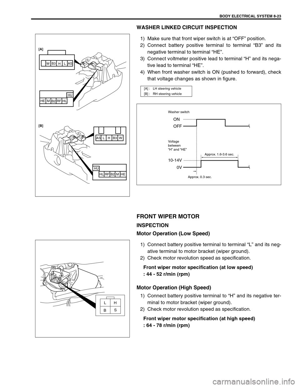
WASHER LINKED CIRCUIT INSPECTION
1) Make sure that front wiper switch is at “OFF” position.
2) Connect battery positive terminal to terminal “B3” and its
negative terminal to terminal “HE”.
3) Connect voltmeter positive lead to terminal “H” and its nega-
tive lead to terminal “HE”.
4) When front washer switch is ON (pushed to forward), check
that voltage changes as shown in figure.
FRONT WIPER MOTOR
INSPECTION
Motor Operation (Low Speed)
1) Connect battery positive terminal to terminal “L” and its neg-
ative terminal to motor bracket (wiper ground).
2) Check motor revolution speed as specification.
Front wiper motor specification (at low speed)
: 44 - 52 r/min (rpm)
Motor Operation (High Speed)
1) Connect battery positive terminal to “H” and its negative ter-
minal to motor bracket (wiper ground).
2) Check motor revolution speed as specification.
Front wiper motor specification (at high speed)
: 64 - 78 r/min (rpm)
[A] : LH steering vehicle
[B] : RH steering vehicle
AS L H B3 W
HU
HL RF B2 M HE
HU
HL RF
B2 M HE [A]
[B]
AS
L
H B3
W
10-14V
Washer switch
Voltage
between
“H” and “HE”
0V ON
OFF
Approx. 0.3 sec.Approx. 1.6-3.6 sec.
LH
S
B