key SUZUKI SWIFT 2000 1.G Transmission Service User Guide
[x] Cancel search | Manufacturer: SUZUKI, Model Year: 2000, Model line: SWIFT, Model: SUZUKI SWIFT 2000 1.GPages: 447, PDF Size: 10.54 MB
Page 116 of 447

7B-74 AUTOMATIC TRANSMISSION (4 A/T)
3) If selector lever is in “P” range, shift selector lever to other
than “P” range with releasing shift lock referring to “SHIFT
LOCK SOLENOID MANUAL RELEASE” in this section.
4) Install cable end (1) and cable casing cap (2) to key interlock
cam (3) and its bracket (4), then install cable (5) to selector
pad (6).
5) With selector lever set at “P” position, turn ignition key to
“ACC” position and then check for following conditions.
With knob button released, ignition key can be turned from
“ACC” position to “LOCK” position.
With knob button pressed, ignition key cannot be turned from
“ACC” position to “LOCK” position.
6) Install steering column referring to Section 3C.
7) Install steering column hole cover.
8) Install center console.
9) Connect negative cable at battery and enable air bag sys-
tem, referring to “ENABLING AIR BAG SYSTEM” in Section
10B (if equipped).
Page 148 of 447
7B-106 AUTOMATIC TRANSMISSION (4 A/T)
VALVE BODY
1. Upper valve body 12. Lock-up control valve 23. Fail valve No.1
2. Upper valve body gasket 13. Lock-up control valve spring 24. Fail valve No.1 sleeve
3. Valve body plate 14. Lock-up signal valve plug 25. Key (short)
4. Lower valve body gasket 15. Lock-up signal valve 26. Key (long)
5. Lower valve body 16. Lock-up signal valve spring 27. Oil strainer
6. Primary regulator valve sleeve 17. Fail valve No.2 sleeve 28. Cooler by-pass valve
7. Primary regulator valve plunger 18. Fail valve No.2 29. Cooler by-pass valve spring
8. Primary regulator valve spring 19. Secondary regulator valve plug 30. Steel ball
9. Washer 20. Secondary regulator valve spring 31. Lock-up control valve
10. Primary regulator valve 21. Secondary regulator valve Apply automatic transmission fluid.
11. Lock-up control valve sleeve 22. Manual valve Do not reuse.
Page 149 of 447
AUTOMATIC TRANSMISSION (4 A/T) 7B-107
DISASSEMBLY
Valve Body Assembly
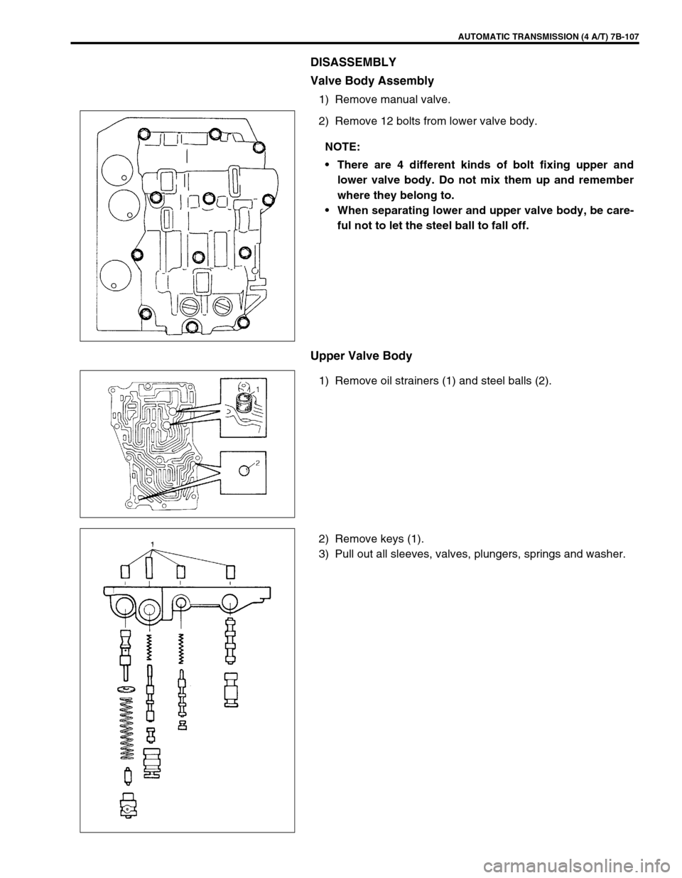
1) Remove manual valve.
2) Remove 12 bolts from lower valve body.
Upper Valve Body
1) Remove oil strainers (1) and steel balls (2).
2) Remove keys (1).
3) Pull out all sleeves, valves, plungers, springs and washer.NOTE:
There are 4 different kinds of bolt fixing upper and
lower valve body. Do not mix them up and remember
where they belong to.
When separating lower and upper valve body, be care-
ful not to let the steel ball to fall off.
Page 150 of 447

7B-108 AUTOMATIC TRANSMISSION (4 A/T)
Valve spring dimensions (Reference)
Lower Valve Body
1) Remove oil strainers (1).
2) Remove solenoid valves, if still attached.
3) Remove keys (2) and pull out all sleeve, plug, spring and
valves.
Valve spring dimensions (Reference)Spring Free length
“a” (mm)Outside diameter
“b” (mm)
Primary regula-
tor valve spring79.2 18.0
Lock-up control
valve spring31.1 8.5
Lock-up signal
valve spring36.1 8.5
3. Fail valve No.1 sleeve
4. Fail valve No.1
5. Cooler by-pass valve
6. Cooler by-pass valve spring
7. Manual valve
8. Secondary regulator valve
9. Secondary regulator valve spring
10. Secondary regulator valve plug
Spring Free length
“a” (mm)Outside diame-
ter “b” (mm)
Secondary regula-
tor valve spring38.7 8.8
Cooler by-pass
valve spring22.8 8.0
Page 151 of 447
AUTOMATIC TRANSMISSION (4 A/T) 7B-109
ASSEMBLY
Upper Valve Body
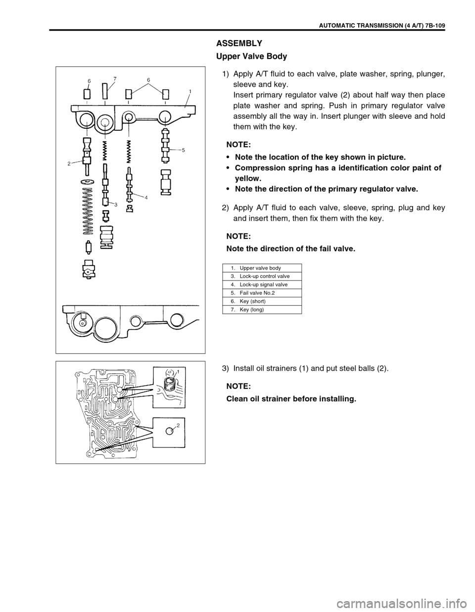
1) Apply A/T fluid to each valve, plate washer, spring, plunger,
sleeve and key.
Insert primary regulator valve (2) about half way then place
plate washer and spring. Push in primary regulator valve
assembly all the way in. Insert plunger with sleeve and hold
them with the key.
2) Apply A/T fluid to each valve, sleeve, spring, plug and key
and insert them, then fix them with the key.
3) Install oil strainers (1) and put steel balls (2).NOTE:
Note the location of the key shown in picture.
Compression spring has a identification color paint of
yellow.
Note the direction of the primary regulator valve.
NOTE:
Note the direction of the fail valve.
1. Upper valve body
3. Lock-up control valve
4. Lock-up signal valve
5. Fail valve No.2
6. Key (short)
7. Key (long)
NOTE:
Clean oil strainer before installing.
Page 152 of 447
7B-110 AUTOMATIC TRANSMISSION (4 A/T)
Lower Valve Body
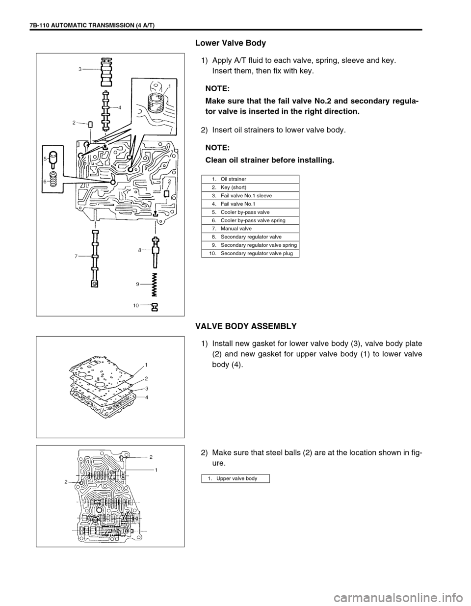
1) Apply A/T fluid to each valve, spring, sleeve and key.
Insert them, then fix with key.
2) Insert oil strainers to lower valve body.
VALVE BODY ASSEMBLY
1) Install new gasket for lower valve body (3), valve body plate
(2) and new gasket for upper valve body (1) to lower valve
body (4).
2) Make sure that steel balls (2) are at the location shown in fig-
ure. NOTE:
Make sure that the fail valve No.2 and secondary regula-
tor valve is inserted in the right direction.
NOTE:
Clean oil strainer before installing.
1. Oil strainer
2. Key (short)
3. Fail valve No.1 sleeve
4. Fail valve No.1
5. Cooler by-pass valve
6. Cooler by-pass valve spring
7. Manual valve
8. Secondary regulator valve
9. Secondary regulator valve spring
10. Secondary regulator valve plug
1. Upper valve body
Page 245 of 447
BODY ELECTRICAL SYSTEM 8-1
6F1
6F2
6G
6H
6K
7A
7A1
7B1
7C1
7D
7E
7F
8A
8
8D
8E
9
10
10A
10B
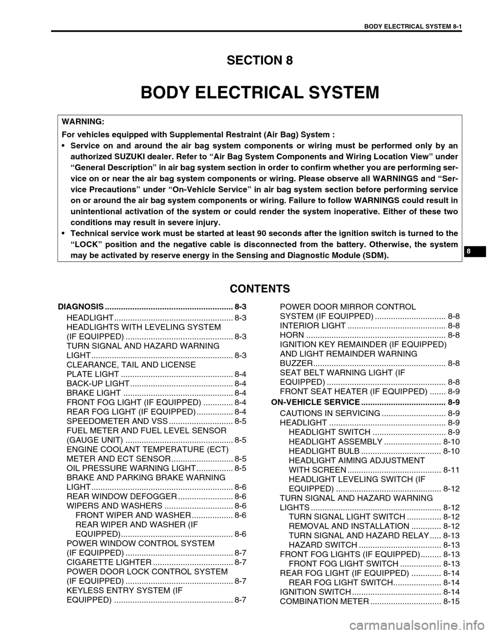
SECTION 8
BODY ELECTRICAL SYSTEM
CONTENTS
DIAGNOSIS ........................................................ 8-3
HEADLIGHT .................................................... 8-3
HEADLIGHTS WITH LEVELING SYSTEM
(IF EQUIPPED) ............................................... 8-3
TURN SIGNAL AND HAZARD WARNING
LIGHT .............................................................. 8-3
CLEARANCE, TAIL AND LICENSE
PLATE LIGHT ................................................. 8-4
BACK-UP LIGHT ............................................. 8-4
BRAKE LIGHT ................................................ 8-4
FRONT FOG LIGHT (IF EQUIPPED) ............. 8-4
REAR FOG LIGHT (IF EQUIPPED) ................ 8-4
SPEEDOMETER AND VSS ............................ 8-5
FUEL METER AND FUEL LEVEL SENSOR
(GAUGE UNIT) ............................................... 8-5
ENGINE COOLANT TEMPERATURE (ECT)
METER AND ECT SENSOR ........................... 8-5
OIL PRESSURE WARNING LIGHT ................ 8-5
BRAKE AND PARKING BRAKE WARNING
LIGHT .............................................................. 8-6
REAR WINDOW DEFOGGER ........................ 8-6
WIPERS AND WASHERS .............................. 8-6
FRONT WIPER AND WASHER .................. 8-6
REAR WIPER AND WASHER (IF
EQUIPPED)................................................. 8-6
POWER WINDOW CONTROL SYSTEM
(IF EQUIPPED) ............................................... 8-7
CIGARETTE LIGHTER ................................... 8-7
POWER DOOR LOCK CONTROL SYSTEM
(IF EQUIPPED) ............................................... 8-7
KEYLESS ENTRY SYSTEM (IF
EQUIPPED) .................................................... 8-7POWER DOOR MIRROR CONTROL
SYSTEM (IF EQUIPPED) ............................... 8-8
INTERIOR LIGHT ........................................... 8-8
HORN ............................................................. 8-8
IGNITION KEY REMAINDER (IF EQUIPPED)
AND LIGHT REMAINDER WARNING
BUZZER.......................................................... 8-8
SEAT BELT WARNING LIGHT (IF
EQUIPPED) .................................................... 8-8
FRONT SEAT HEATER (IF EQUIPPED) ....... 8-9
ON-VEHICLE SERVICE ..................................... 8-9
CAUTIONS IN SERVICING ............................ 8-9
HEADLIGHT ................................................... 8-9
HEADLIGHT SWITCH ................................ 8-9
HEADLIGHT ASSEMBLY ......................... 8-10
HEADLIGHT BULB ................................... 8-10
HEADLIGHT AIMING ADJUSTMENT
WITH SCREEN ......................................... 8-11
HEADLIGHT LEVELING SWITCH (IF
EQUIPPED) .............................................. 8-12
TURN SIGNAL AND HAZARD WARNING
LIGHTS ......................................................... 8-12
TURN SIGNAL LIGHT SWITCH ............... 8-12
REMOVAL AND INSTALLATION ............. 8-12
TURN SIGNAL AND HAZARD RELAY ..... 8-13
HAZARD SWITCH .................................... 8-13
FRONT FOG LIGHTS (IF EQUIPPED)......... 8-13
FRONT FOG LIGHT SWITCH .................. 8-13
REAR FOG LIGHT (IF EQUIPPED) ............. 8-14
REAR FOG LIGHT SWITCH..................... 8-14
IGNITION SWITCH ....................................... 8-14
COMBINATION METER ............................... 8-15 WARNING:
For vehicles equipped with Supplemental Restraint (Air Bag) System :
Service on and around the air bag system components or wiring must be performed only by an
authorized SUZUKI dealer. Refer to “Air Bag System Components and Wiring Location View” under
“General Description” in air bag system section in order to confirm whether you are performing ser-
vice on or near the air bag system components or wiring. Please observe all WARNINGS and “Ser-
vice Precautions” under “On-Vehicle Service” in air bag system section before performing service
on or around the air bag system components or wiring. Failure to follow WARNINGS could result in
unintentional activation of the system or could render the system inoperative. Either of these two
conditions may result in severe injury.
Technical service work must be started at least 90 seconds after the ignition switch is turned to the
“LOCK” position and the negative cable is disconnected from the battery. Otherwise, the system
may be activated by reserve energy in the Sensing and Diagnostic Module (SDM).
Page 246 of 447
8-2 BODY ELECTRICAL SYSTEM
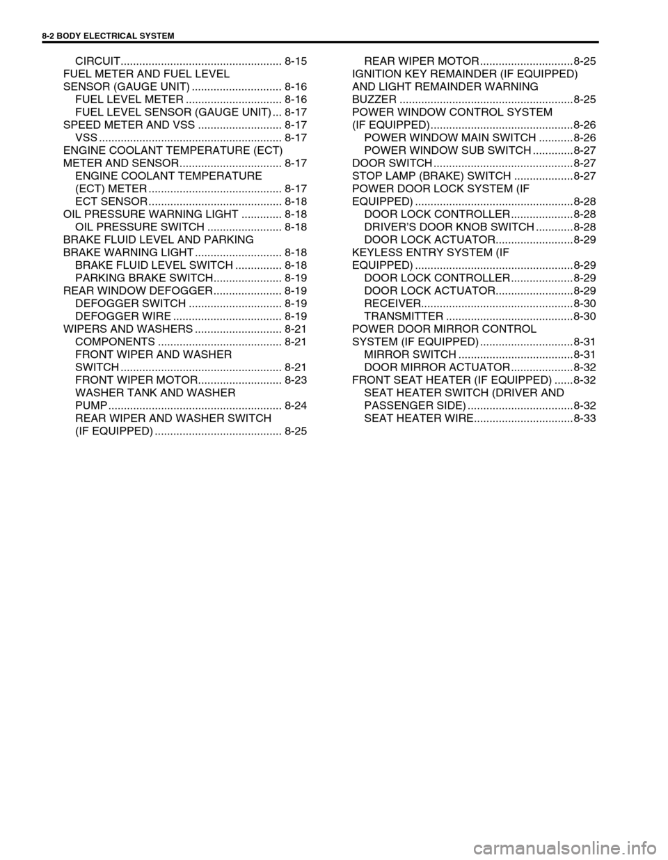
CIRCUIT.................................................... 8-15
FUEL METER AND FUEL LEVEL
SENSOR (GAUGE UNIT) ............................. 8-16
FUEL LEVEL METER ............................... 8-16
FUEL LEVEL SENSOR (GAUGE UNIT) ... 8-17
SPEED METER AND VSS ........................... 8-17
VSS ........................................................... 8-17
ENGINE COOLANT TEMPERATURE (ECT)
METER AND SENSOR................................. 8-17
ENGINE COOLANT TEMPERATURE
(ECT) METER ........................................... 8-17
ECT SENSOR ........................................... 8-18
OIL PRESSURE WARNING LIGHT ............. 8-18
OIL PRESSURE SWITCH ........................ 8-18
BRAKE FLUID LEVEL AND PARKING
BRAKE WARNING LIGHT ............................ 8-18
BRAKE FLUID LEVEL SWITCH ............... 8-18
PARKING BRAKE SWITCH...................... 8-19
REAR WINDOW DEFOGGER...................... 8-19
DEFOGGER SWITCH .............................. 8-19
DEFOGGER WIRE ................................... 8-19
WIPERS AND WASHERS ............................ 8-21
COMPONENTS ........................................ 8-21
FRONT WIPER AND WASHER
SWITCH .................................................... 8-21
FRONT WIPER MOTOR........................... 8-23
WASHER TANK AND WASHER
PUMP ........................................................ 8-24
REAR WIPER AND WASHER SWITCH
(IF EQUIPPED) ......................................... 8-25REAR WIPER MOTOR .............................. 8-25
IGNITION KEY REMAINDER (IF EQUIPPED)
AND LIGHT REMAINDER WARNING
BUZZER ........................................................ 8-25
POWER WINDOW CONTROL SYSTEM
(IF EQUIPPED).............................................. 8-26
POWER WINDOW MAIN SWITCH ........... 8-26
POWER WINDOW SUB SWITCH ............. 8-27
DOOR SWITCH ............................................. 8-27
STOP LAMP (BRAKE) SWITCH ................... 8-27
POWER DOOR LOCK SYSTEM (IF
EQUIPPED) ................................................... 8-28
DOOR LOCK CONTROLLER .................... 8-28
DRIVER’S DOOR KNOB SWITCH ............ 8-28
DOOR LOCK ACTUATOR......................... 8-29
KEYLESS ENTRY SYSTEM (IF
EQUIPPED) ................................................... 8-29
DOOR LOCK CONTROLLER .................... 8-29
DOOR LOCK ACTUATOR......................... 8-29
RECEIVER................................................. 8-30
TRANSMITTER ......................................... 8-30
POWER DOOR MIRROR CONTROL
SYSTEM (IF EQUIPPED) .............................. 8-31
MIRROR SWITCH ..................................... 8-31
DOOR MIRROR ACTUATOR .................... 8-32
FRONT SEAT HEATER (IF EQUIPPED) ...... 8-32
SEAT HEATER SWITCH (DRIVER AND
PASSENGER SIDE) .................................. 8-32
SEAT HEATER WIRE................................ 8-33
Page 251 of 447
BODY ELECTRICAL SYSTEM 8-7
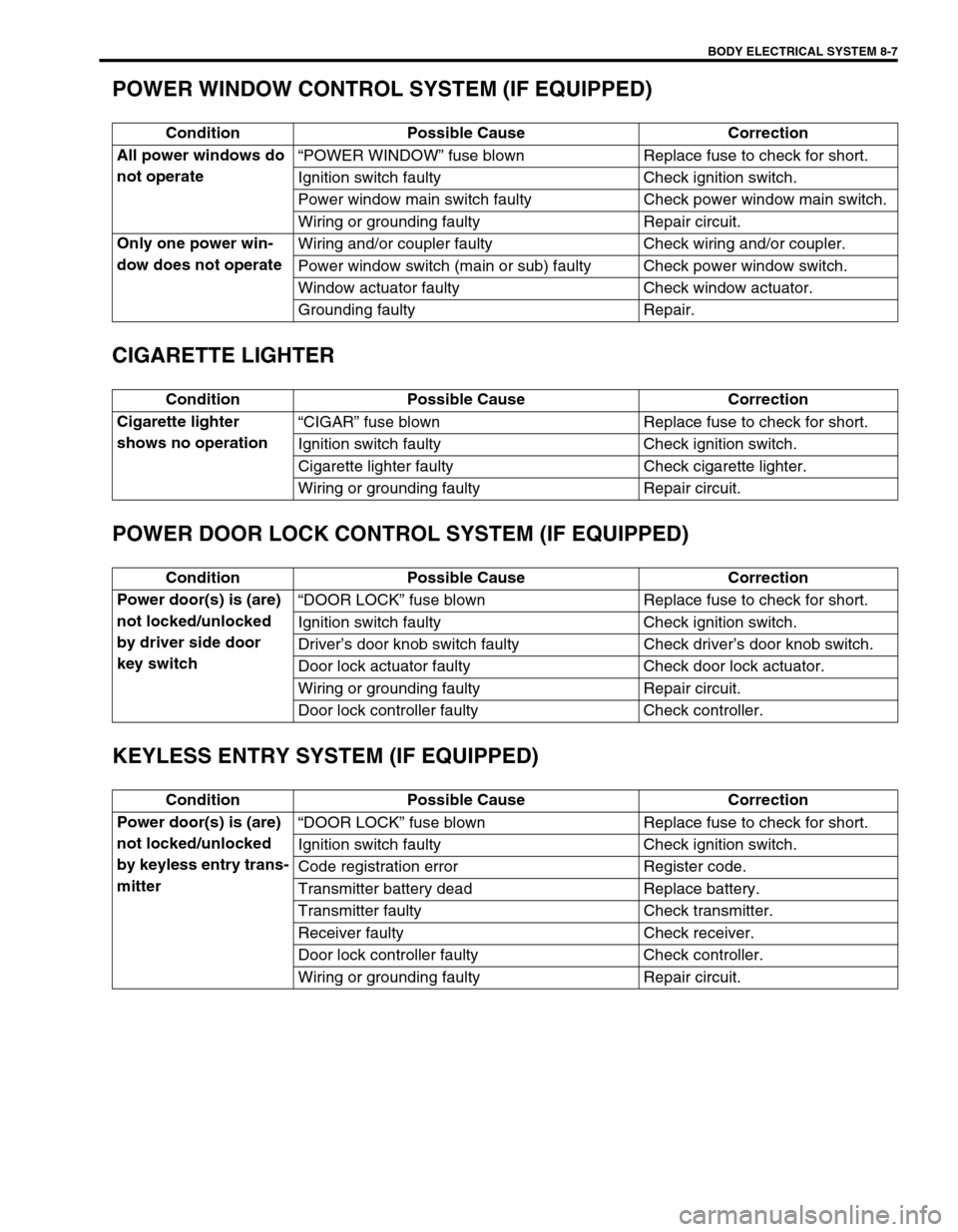
POWER WINDOW CONTROL SYSTEM (IF EQUIPPED)
CIGARETTE LIGHTER
POWER DOOR LOCK CONTROL SYSTEM (IF EQUIPPED)
KEYLESS ENTRY SYSTEM (IF EQUIPPED)
Condition Possible Cause Correction
All power windows do
not operate“POWER WINDOW” fuse blown Replace fuse to check for short.
Ignition switch faulty Check ignition switch.
Power window main switch faulty Check power window main switch.
Wiring or grounding faulty Repair circuit.
Only one power win-
dow does not operateWiring and/or coupler faulty Check wiring and/or coupler.
Power window switch (main or sub) faulty Check power window switch.
Window actuator faulty Check window actuator.
Grounding faulty Repair.
Condition Possible Cause Correction
Cigarette lighter
shows no operation“CIGAR” fuse blown Replace fuse to check for short.
Ignition switch faulty Check ignition switch.
Cigarette lighter faulty Check cigarette lighter.
Wiring or grounding faulty Repair circuit.
Condition Possible Cause Correction
Power door(s) is (are)
not locked/unlocked
by driver side door
key switch“DOOR LOCK” fuse blown Replace fuse to check for short.
Ignition switch faulty Check ignition switch.
Driver’s door knob switch faulty Check driver’s door knob switch.
Door lock actuator faulty Check door lock actuator.
Wiring or grounding faulty Repair circuit.
Door lock controller faulty Check controller.
Condition Possible Cause Correction
Power door(s) is (are)
not locked/unlocked
by keyless entry trans-
mitter“DOOR LOCK” fuse blown Replace fuse to check for short.
Ignition switch faulty Check ignition switch.
Code registration error Register code.
Transmitter battery dead Replace battery.
Transmitter faulty Check transmitter.
Receiver faulty Check receiver.
Door lock controller faulty Check controller.
Wiring or grounding faulty Repair circuit.
Page 252 of 447
8-8 BODY ELECTRICAL SYSTEM
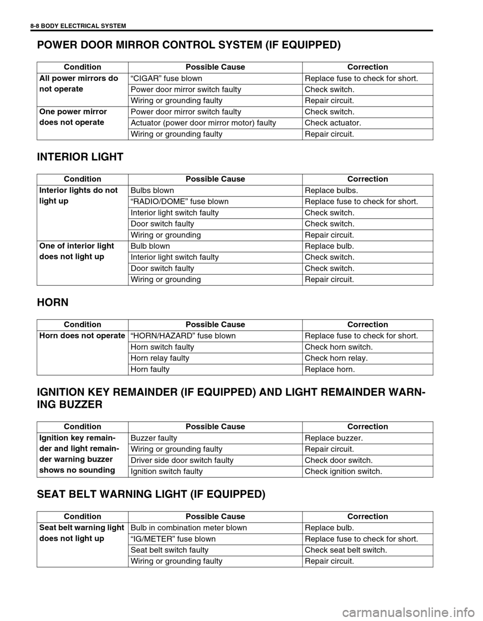
POWER DOOR MIRROR CONTROL SYSTEM (IF EQUIPPED)
INTERIOR LIGHT
HORN
IGNITION KEY REMAINDER (IF EQUIPPED) AND LIGHT REMAINDER WARN-
ING BUZZER
SEAT BELT WARNING LIGHT (IF EQUIPPED)
Condition Possible Cause Correction
All power mirrors do
not operate“CIGAR” fuse blown Replace fuse to check for short.
Power door mirror switch faulty Check switch.
Wiring or grounding faulty Repair circuit.
One power mirror
does not operatePower door mirror switch faulty Check switch.
Actuator (power door mirror motor) faulty Check actuator.
Wiring or grounding faulty Repair circuit.
Condition Possible Cause Correction
Interior lights do not
light upBulbs blown Replace bulbs.
“RADIO/DOME” fuse blown Replace fuse to check for short.
Interior light switch faulty Check switch.
Door switch faulty Check switch.
Wiring or grounding Repair circuit.
One of interior light
does not light upBulb blown Replace bulb.
Interior light switch faulty Check switch.
Door switch faulty Check switch.
Wiring or grounding Repair circuit.
Condition Possible Cause Correction
Horn does not operate
“HORN/HAZARD” fuse blown Replace fuse to check for short.
Horn switch faulty Check horn switch.
Horn relay faulty Check horn relay.
Horn faulty Replace horn.
Condition Possible Cause Correction
Ignition key remain-
der and light remain-
der warning buzzer
shows no soundingBuzzer faulty Replace buzzer.
Wiring or grounding faulty Repair circuit.
Driver side door switch faulty Check door switch.
Ignition switch faulty Check ignition switch.
Condition Possible Cause Correction
Seat belt warning light
does not light upBulb in combination meter blown Replace bulb.
“IG/METER” fuse blown Replace fuse to check for short.
Seat belt switch faulty Check seat belt switch.
Wiring or grounding faulty Repair circuit.