charging SUZUKI SWIFT 2000 1.G Transmission Service Workshop Manual
[x] Cancel search | Manufacturer: SUZUKI, Model Year: 2000, Model line: SWIFT, Model: SUZUKI SWIFT 2000 1.GPages: 447, PDF Size: 10.54 MB
Page 247 of 447

BODY ELECTRICAL SYSTEM 8-3
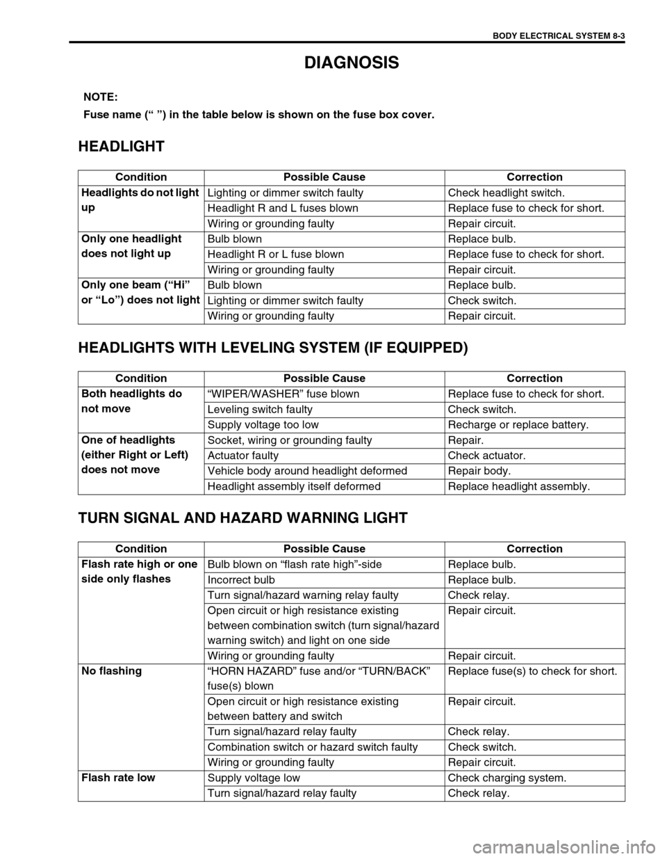
DIAGNOSIS
HEADLIGHT
HEADLIGHTS WITH LEVELING SYSTEM (IF EQUIPPED)
TURN SIGNAL AND HAZARD WARNING LIGHT
NOTE:
Fuse name (“ ”) in the table below is shown on the fuse box cover.
Condition Possible Cause Correction
Headlights do not light
upLighting or dimmer switch faulty Check headlight switch.
Headlight R and L fuses blown Replace fuse to check for short.
Wiring or grounding faulty Repair circuit.
Only one headlight
does not light upBulb blown Replace bulb.
Headlight R or L fuse blown Replace fuse to check for short.
Wiring or grounding faulty Repair circuit.
Only one beam (“Hi”
or “Lo”) does not lightBulb blown Replace bulb.
Lighting or dimmer switch faulty Check switch.
Wiring or grounding faulty Repair circuit.
Condition Possible Cause Correction
Both headlights do
not move“WIPER/WASHER” fuse blown Replace fuse to check for short.
Leveling switch faulty Check switch.
Supply voltage too low Recharge or replace battery.
One of headlights
(either Right or Left)
does not moveSocket, wiring or grounding faulty Repair.
Actuator faulty Check actuator.
Vehicle body around headlight deformed Repair body.
Headlight assembly itself deformed Replace headlight assembly.
Condition Possible Cause Correction
Flash rate high or one
side only flashesBulb blown on “flash rate high”-side Replace bulb.
Incorrect bulb Replace bulb.
Turn signal/hazard warning relay faulty Check relay.
Open circuit or high resistance existing
between combination switch (turn signal/hazard
warning switch) and light on one sideRepair circuit.
Wiring or grounding faulty Repair circuit.
No flashing
“HORN HAZARD” fuse and/or “TURN/BACK”
fuse(s) blownReplace fuse(s) to check for short.
Open circuit or high resistance existing
between battery and switchRepair circuit.
Turn signal/hazard relay faulty Check relay.
Combination switch or hazard switch faulty Check switch.
Wiring or grounding faulty Repair circuit.
Flash rate low
Supply voltage low Check charging system.
Turn signal/hazard relay faulty Check relay.
Page 410 of 447

10B-36 AIR BAG SYSTEM
DTC B1032 – POWER SOURCE VOLTAGE LOW
WIRING DIAGRAM
DTC WILL SET WHEN
The power source voltage is below an approx. 8 V for specified time.
TABLE TEST DESCRIPTION
STEP 1 : Check if voltage applied to SDM is within normal range.
STEP 2 : Check if DTC 32 still exists.
DIAGNOSTIC FLOW TABLE
[A] : Air bag harness 2. Ignition switch 4. SDM
1. From main fuse 3.“AIR BAG” fuse 5. Ground for air bag system
1
2RED BLK/YELRED
3
5
BLK“Q06”
Q06-4
Q06-17IG
GND4
“G39”“Q02”
[A]
CAUTION:
Be sure to perform AIR BAG DIAGNOSTIC SYSTEM CHECK before starting diagnosis according to
flow table.
When measurement of resistance or voltage is required in this table, use a tester along with a cor-
rect terminal adapter from special tool (Connector test adapter kit).
When a check for proper connection is required, refer to INTERMITTENT AND POOR CONNEC-
TIONS in this section.
If there is open circuit in the air bag wire harness, connector or terminal is found damaged, replace
the wire harness, connector and terminal as an assembly.
Step Action Yes No
1 1) Measure voltage on battery.
Is voltage 11 V or more?Go to step 2. Check Charging System
and repair as necessary.
(Refer to DIAGNOSIS in
Section 6H)
2 1) With ignition switch OFF, disconnect SDM.
2) Check proper connection to SDM at “Q06-4”
terminal.
3) If OK then ignition switch ON, and then
check voltage from “Q06-4” terminal on
SDM connector to body ground.
Is voltage 8 V or more?Go to step 4. Go to step 3.
Page 411 of 447

AIR BAG SYSTEM 10B-37
Fig. for STEP 2
Fig. for STEP 3
Special tool
(A) : 09932-76010 3 1) With ignition switch OFF, disconnect “G39”
connector.
2) Check proper connection at “G39-1” (“RED”
wire) terminal.
3) If OK then ignition switch ON, and then
check voltage from “G39-1” (“RED” wire)
terminal on instrument panel harness to
body ground.
Is voltage 8 V or more?Repair poor connection,
high resistance in “RED”
or “BLK/YEL” circuit of air
bag harness or “AIR BAG”
fuse.Possibly faulty points are
as follows. Check each of
them and repair as neces-
sary.
Circuit from battery to
“G39” connector
Charging System
(Refer to DIAGNOSIS
in Section 6H)
4 1) With ignition switch OFF, reconnect SDM.
With ignition switch ON, is DTC B1032 current?Substitute a known-good
SDM and recheck.Check Charging System
and repair as necessary.
(Refer to DIAGNOSIS in
Section 6H) Step Action Yes No
1. Instrument panel harness side connector
2.“RED” wire terminal
NOTE:
Upon completion of inspection and repair work, perform following items.
Reconnect all air bag system components, ensure all components are properly mounted.
Clear diagnostic trouble codes (Refer to DTC CLEARANCE), if any.
Repeat AIR BAG DIAGNOSTIC SYSTEM CHECK to confirm that the trouble has been corrected.