steering SUZUKI SWIFT 2000 1.G Transmission Service User Guide
[x] Cancel search | Manufacturer: SUZUKI, Model Year: 2000, Model line: SWIFT, Model: SUZUKI SWIFT 2000 1.GPages: 447, PDF Size: 10.54 MB
Page 270 of 447

8-26 BODY ELECTRICAL SYSTEM
POWER WINDOW CONTROL SYSTEM (IF
EQUIPPED)
POWER WINDOW MAIN SWITCH
INSPECTION
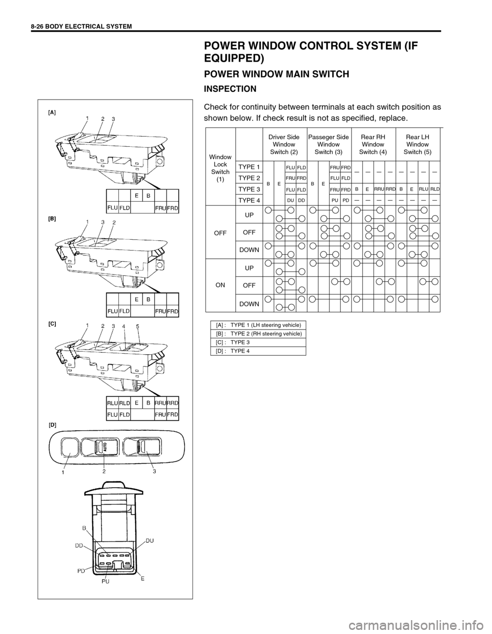
Check for continuity between terminals at each switch position as
shown below. If check result is not as specified, replace.
[A] : TYPE 1 (LH steering vehicle)
[B] : TYPE 2 (RH steering vehicle)
[C] : TYPE 3
[D] : TYPE 4
Window
Lock
Switch
(1)Driver Side
Window
Switch (2)Passeger Side
Window
Switch (3)Rear RH
Window
Switch (4)Rear LH
Window
Switch (5)
OFF
ONTYPE 1
TYPE 2
TYPE 3
TYPE 4
UP
OFF
DOWN
UP
OFF
DOWN
B
B EBE
E FLU
FRU
FLU
DUFLD
FRD
FLD
DDFRU
RRU RRD B
ERLU RLD FLU
FRU
PUFRD
FLD
FRD
PD
Page 280 of 447

8G-2 IMMOBILIZER CONTROL SYSTEM
PROCEDURE AFTER IMMOBILIZER CONTROL
MODULE REPLACEMENT ........................... 8G-24
PROCEDURE AFTER ECM
REPLACEMENT............................................ 8G-25SPECIAL TOOL ............................................ 8G-25
GENERAL DESCRIPTION
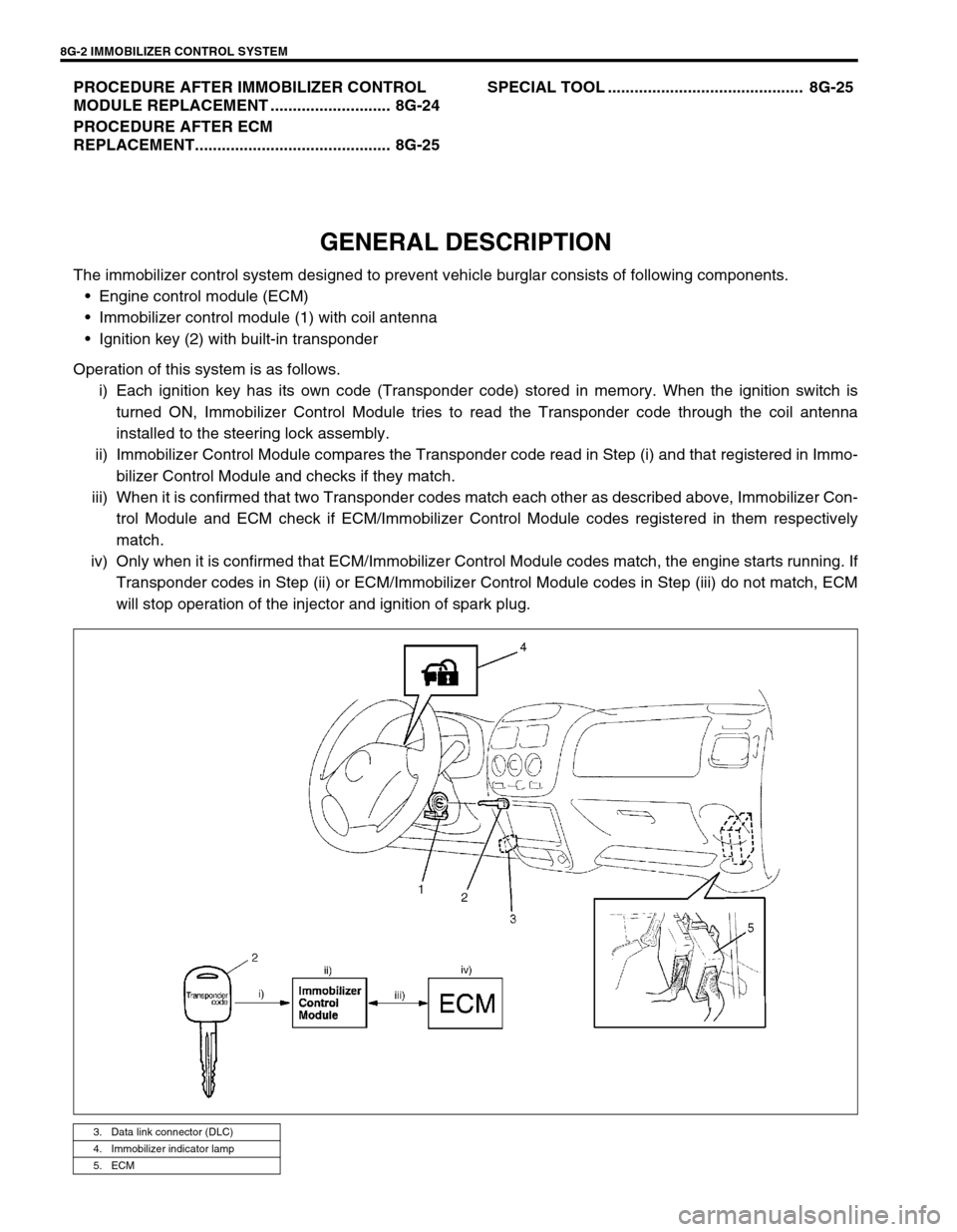
The immobilizer control system designed to prevent vehicle burglar consists of following components.
Engine control module (ECM)
Immobilizer control module (1) with coil antenna
Ignition key (2) with built-in transponder
Operation of this system is as follows.
i) Each ignition key has its own code (Transponder code) stored in memory. When the ignition switch is
turned ON, Immobilizer Control Module tries to read the Transponder code through the coil antenna
installed to the steering lock assembly.
ii) Immobilizer Control Module compares the Transponder code read in Step (i) and that registered in Immo-
bilizer Control Module and checks if they match.
iii) When it is confirmed that two Transponder codes match each other as described above, Immobilizer Con-
trol Module and ECM check if ECM/Immobilizer Control Module codes registered in them respectively
match.
iv) Only when it is confirmed that ECM/Immobilizer Control Module codes match, the engine starts running. If
Transponder codes in Step (ii) or ECM/Immobilizer Control Module codes in Step (iii) do not match, ECM
will stop operation of the injector and ignition of spark plug.
3. Data link connector (DLC)
4. Immobilizer indicator lamp
5. ECM
Page 298 of 447

8G-20 IMMOBILIZER CONTROL SYSTEM
INSPECTION OF ECM, IMMOBILIZER CON-
TROL MODULE AND ITS CIRCUIT
ECM, Immobilizer Control Module and its circuit can be checked
at ECM wiring couplers and Immobilizer Control Module wiring
coupler by measuring voltage. Described here is only inspection
of Immobilizer Control Module. For inspection of ECM, refer to
“ENGINE & EMISSION CONTROL INPUT/OUTPUT TABLE” in
Section 6E1.
Voltage Check
1) Remove Immobilizer Control Module from steering lock
assembly with ignition switch OFF, referring to “REMOVAL”
of “IMMOBILIZER CONTROL MODULE” in this section.
2) Connect Immobilizer Control Module coupler to Immobilizer
Control Module.
3) Check voltage at each terminal of coupler connected.CAUTION:
Immobilizer Control Module cannot be checked by itself.
It is strictly prohibited to connect voltmeter or ohmmeter
to Immobilizer Control Module with coupler disconnected
from it.
NOTE:
As each terminal voltage is affected by the battery volt-
age, confirm that it is 11V or more when ignition switch is
ON.
1. Immobilizer Control Module
2. Immobilizer Control Module coupler
3. Body ground
TERMINAL CIRCUIT NOMAL VOLTAGE CONDITION
G06-1 Ground––
G06-2Data link connector
(Serial data terminal)4 – 5V Ignition switch ON
G06-3 Ignition signal10 – 14V Ignition switch ON
0 – 0.8V Ignition switch OFF
G06-4 Power source 10 – 14V Ignition switch ON
Page 300 of 447

8G-22 IMMOBILIZER CONTROL SYSTEM
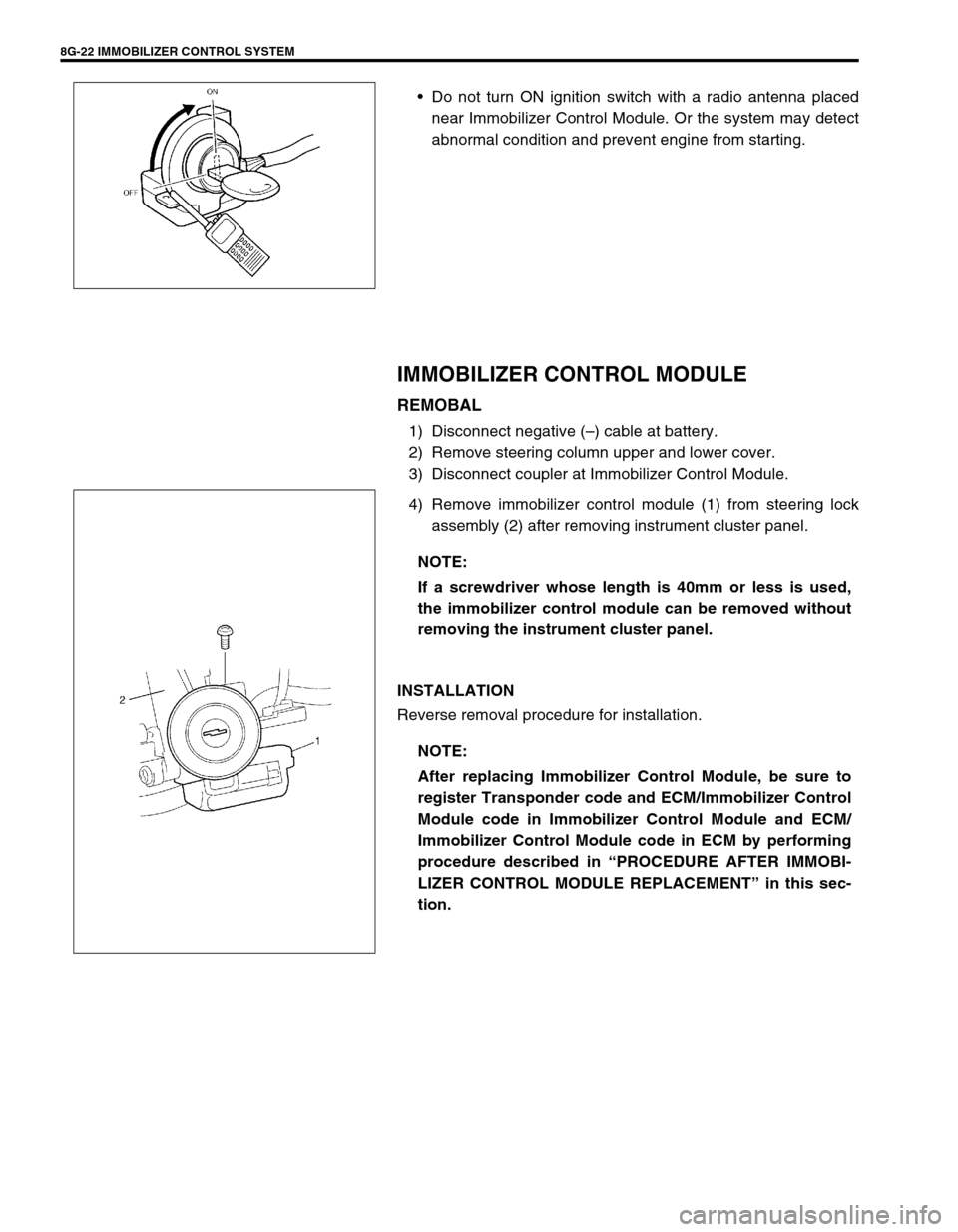
Do not turn ON ignition switch with a radio antenna placed
near Immobilizer Control Module. Or the system may detect
abnormal condition and prevent engine from starting.
IMMOBILIZER CONTROL MODULE
REMOBAL
1) Disconnect negative (–) cable at battery.
2) Remove steering column upper and lower cover.
3) Disconnect coupler at Immobilizer Control Module.
4) Remove immobilizer control module (1) from steering lock
assembly (2) after removing instrument cluster panel.
INSTALLATION
Reverse removal procedure for installation.
NOTE:
If a screwdriver whose length is 40mm or less is used,
the immobilizer control module can be removed without
removing the instrument cluster panel.
NOTE:
After replacing Immobilizer Control Module, be sure to
register Transponder code and ECM/Immobilizer Control
Module code in Immobilizer Control Module and ECM/
Immobilizer Control Module code in ECM by performing
procedure described in “PROCEDURE AFTER IMMOBI-
LIZER CONTROL MODULE REPLACEMENT” in this sec-
tion.
Page 336 of 447
![SUZUKI SWIFT 2000 1.G Transmission Service User Guide 9-32 BODY SERVICE
Hole to hole distance
[B] : 5 door model f. Side sill scuff installation rear hole l. Rear door rear notch
a. Front door upper hinge installation hole g. Front shoulder adjuster inst SUZUKI SWIFT 2000 1.G Transmission Service User Guide 9-32 BODY SERVICE
Hole to hole distance
[B] : 5 door model f. Side sill scuff installation rear hole l. Rear door rear notch
a. Front door upper hinge installation hole g. Front shoulder adjuster inst](/img/20/7605/w960_7605-335.png)
9-32 BODY SERVICE
Hole to hole distance
[B] : 5 door model f. Side sill scuff installation rear hole l. Rear door rear notch
a. Front door upper hinge installation hole g. Front shoulder adjuster installation upper
holem. Rear door switch installation hole
b. Front door lower hinge installation hole h. Rear door upper hinge installation hole n. Side soil scuff installation rear hole
c. Front pillar inner trim installation lower hole i. Front door switch installation hole o. Parking brake cable bracket installation rear
hole
d. Front pillar inner trim installation upper hole j. Rear door lower hinge installation hole p. Steering support member installation hole
e. Assistant grip installation front hole k. Assistant grip installation hole
a-g : 1166 mm (45.90 in.) d-i : 820 mm (32.28 in.) i-o : 742 mm (29.21 in.)
a-h : 942 mm (37.09 in.) d-o : 1252 mm (49.29 in.) j-m : 895 mm (35.24 in.)
a-i : 901 mm (35.47 in.) e- f : 1077 mm (42.40 in.) k-n : 1089 mm (42.87 in.)
b-i : 891 mm (35.08 in.) e-o : 1244 mm (48.98 in.) k-o : 1321 mm (52.01 in.)
b-j : 902 mm (35.51 in.) f-g: 1048 mm (41.26 in.) l-n : 948 mm (37.32 in.)
b-o : 1222 mm (48.11 in.) f-o 785 mm (30.91 in.) l-o : 1323 mm (52.09 in.)
c-f : 884 mm (34.80 in.) g-l : 621 mm (24.45 in.) m-o : 1111 mm (43.74 in.)
c-o: 1282 mm (50.47 in.) g-o : 1147 mm (45.16 in.) n-o : 813 mm (32.00 in.)
d-f : 993 mm (39.09 in.) h-l : 846 mm (33.31 in.) o-p : 1229 mm (48.39 in.)
d-g : 580 mm (22.83 in.) h-m : 813 mm (32.01 in.)
a
c
gd
ek
l
m
n
i
h
bf
j
a
c
dl
k
g
e
n
m
i
f
b o
o [B]
Page 342 of 447

9-38 BODY SERVICE
INSTRUMENTATION AND DRIVER INFORMATION
INSTRUMENT PANEL
REMOVAL
1) Disconnect negative cable at battery.
2) Disable air bag system, if equipped. Refer to “DISABLE AIR
BAG SYSTEM” in Section 10B.
3) Remove steering column hole cover (1).
4) Remove glove box (1) and food latch release lever (2).
5) Disconnect instrument panel harness connectors, antenna
and heater control cables which need to be disconnected for
removal for instrument panel.
6) Remove instrument panel ground wire.
7) Remove steering column assembly referring to “STEERING
COLUMN ASSEMBLY” in Section 3C.
8) Remove front pillar trims (1) and dash side trims (2).
9) Remove speaker covers (3).WARNING:
See WARNING at the beginning of this section.
“A”
“A”“A”
“A”
“A”
1
2“A” 1
3
“A”
Page 343 of 447

BODY SERVICE 9-39
10) Remove instrument panel mounting bolts (2).
11) Remove instrument panel (1) with steering support member
and instrument panel harness.
INSTALLATION
Reverse removal procedure to install instrument panel noting the
following instructions.
When installing each part, be careful not to catch any cable
or wiring harness.
Tighten instrument panel mounting bolts (1) to specified
torque
Tightening torque
Instrument panel mounting bolts (a) :
23 N·m (2.3 kg-m, 17.0 lb-ft)
When installing steering column assembly, refer to “STEER-
ING COLUMN ASSEMBLY” in Section 3C.
Adjust control cables. Refer to “HEATER CONTROL
ASSEMBLY” in Section 1A.
Enable air bag system if equipped. Refer to “ENABLING AIR
BAG SYSTEM” in Section 10B.
2
2
22 2
1
1, (a)1, (a)
Page 351 of 447

BODY SERVICE 9-47
IGNITION SWITCH LOCK CYLINDER
REMOVAL AND INSTALLATION
Refer to “STEERING LOCK ASSEMBLY (IGNITION SWITCH)” in
Section 3C.
ELECTRICAL DIAGNOSIS
For ignition switch electrical troubleshooting, refer to “IGNITION
SWITCH” in Section 8.
EXTERIOR AND INTERIOR TRIM
FLOOR CARPET
REMOVAL
1) Remove front seats and rear seat cushion.
2) Remove seat belt lower anchor bolt.
3) Remove dash side trims, front side sill scuffs, center pillar inner lower trims, quarter inner trims and rear side
sill scuffs.
4) Remove parking brake lever cover and console box.
5) Remove floor carpet.
INSTALLATION
Reverse removal sequence to install front floor carpet, noting the following instruction.
For tightening torque of seat belt anchor bolt, refer to “FRONT SEAT BELT” in Section 10.
1. Floor carpet
2. Dash panel silencer
3. Silencer seat
Page 369 of 447

RESTRAINT SYSTEM 10-3
Driver and Front Passenger Air Bags and Seat Belt Pretensioners
With the air bag system which includes air bags for both the driver’s and passenger’s sides as well as the seat
belt pretensioners, the pretensioner takes up the sag of the seat belt, the driver air bag (inflator) module is
deployed from the center of the steering column and the passenger air bag (inflator) module from the top of the
instrument panel in front of the front passenger seat in occurrence of a front collision with an impact larger than
a certain set value to supplement protection offered by the driver and front passenger seat belts.
SYSTEM SPECIFICATION
SEAT BELT PRETENSIONER (IF EQUIPPED)
Some seat belts of the driver and front passenger seats are provided with a pretensioner as an optional function
unit. The pretensioner is incorporated in retractor assembly and controlled by SDM as one of air bag system
components. It will be activated at the same time as the air bag when an impact at the front of vehicle exceeds
the specified value.
When servicing seat belt (retractor assembly) with pretensioner, be sure to observe all WARNINGS and CAU-
TIONS in this section and “SERVICE PRECAUTIONS” of “ON-VEHICLE SERVICE” in Section 10B
DIAGNOSIS
For diagnosis of air bag system (including in seat belt pretensioner), refer to Section 10B.
INSPECTION AND REPAIR REQUIRED AFTER ACCIDENT
After an accident, whether the seat belt pretensioner has been activated or not, be sure to perform checks and
repairs described on “REPAIRS AND INSPECTIONS REQUIRED AFTER ACCIDENT” under “DIAGNOSIS” in
Section 10B.Type 1 Type 2 Type 3
Front
seatSeat belt with ELRDriver air bag
Seat belt with ELR and
pretensionerDriver and front passenger air bags
Seat belt wit ELR and pretensioner
Rear
seatSeat belt with A-ELR
(right and left)
Seat belt (center)Seat belt with A-ELR
(right and left)
Seat belt (center)Seat belt with A-ELR (right and left)
Seat belt (center)
CAUTION:
Do not reuse the seat belt pretensioner (retractor assembly) that has operated but replace it with a
new one as an assembly. For checking procedure of its operation, refer to “SERVICE PRECAUTIONS”
of “ON-VEHICLE SERVICE” in Section 10B.
Page 377 of 447

AIR BAG SYSTEM 10B-3
GENERAL DESCRIPTION
With the air bag system which includes air bags for both the
driver’s and passenger’s sides as well as the seat belt pretension-
ers (if equipped), the sag of the seat belt is taken up (for seat belt
with pretensioner), the driver air bag (inflator) module is deployed
from the center of the steering column and the passenger air bag
(inflator) module from the top of the instrument panel in front of
the front passenger seat in occurrence of a front collision with an
impact larger than a certain set value to supplement protection
offered by the driver and front passenger seat belts.
The air bag system is designed to activate only in severe frontal
collisions. It is not designed to activate in rear impacts, side
impacts, rollovers, or minor frontal collisions, since it would offer
no protection in those types of accidents.
1. Driver side air bag
2. Passenger side air bag
3. Seat belt pretensioner (if equipped)