steering SUZUKI SWIFT 2000 1.G Transmission Service Workshop Manual
[x] Cancel search | Manufacturer: SUZUKI, Model Year: 2000, Model line: SWIFT, Model: SUZUKI SWIFT 2000 1.GPages: 447, PDF Size: 10.54 MB
Page 110 of 447

7B-68 AUTOMATIC TRANSMISSION (4 A/T)
DIFFERENTIAL SIDE OIL SEAL
REPLACEMENT
1) Lift up vehicle and drain transmission oil.
2) Remove drive shaft joints from differential gear of transmis-
sion.
Refer to Section 4 for procedure to disconnect drive shaft
joints.
For differential side oil seal removal, it is not necessary to
remove drive shafts from steering knuckle.
For 4WD vehicle, remove transfer referring to Section 7D.
3) Remove differential side oil seal (1) by using flat end rod or
like.
4) Install new differential side oil seal by using special tool.
Special tool
(A) : 09940-53111
(B) : 09913-75510
5) Install drive shaft referring to Section 4.
6) Refill A/T fluid referring to “FLUID CHANGE” in this section. NOTE:
For oil seal installation, press-fit oil seal so that transmis-
sion case end face is flush with oil seal end face.
2. Steering gear box
3. A/T oil pan
4. Torque converter hous-
ing
5. Transmission case
Page 115 of 447
AUTOMATIC TRANSMISSION (4 A/T) 7B-73
REMOVAL
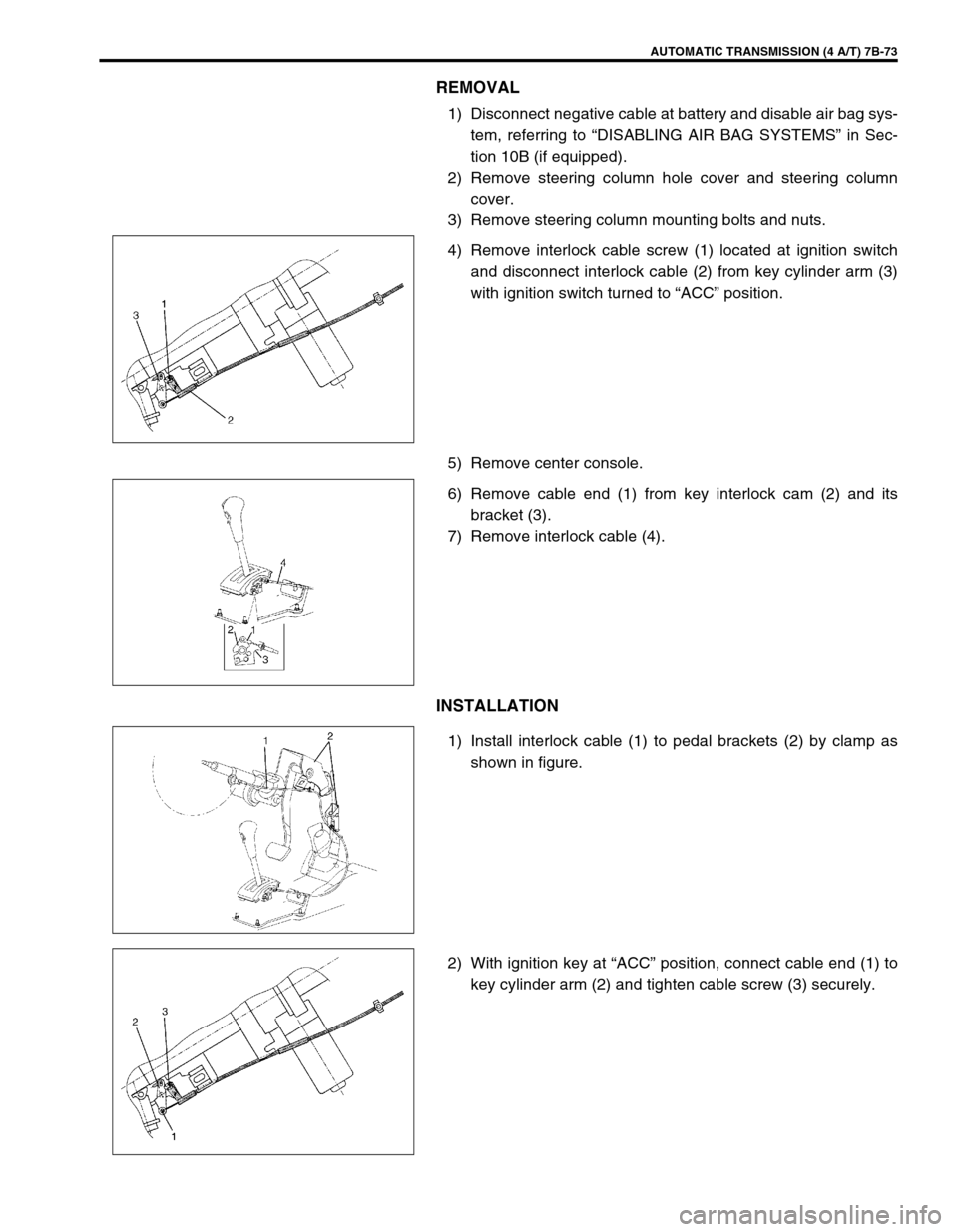
1) Disconnect negative cable at battery and disable air bag sys-
tem, referring to “DISABLING AIR BAG SYSTEMS” in Sec-
tion 10B (if equipped).
2) Remove steering column hole cover and steering column
cover.
3) Remove steering column mounting bolts and nuts.
4) Remove interlock cable screw (1) located at ignition switch
and disconnect interlock cable (2) from key cylinder arm (3)
with ignition switch turned to “ACC” position.
5) Remove center console.
6) Remove cable end (1) from key interlock cam (2) and its
bracket (3).
7) Remove interlock cable (4).
INSTALLATION
1) Install interlock cable (1) to pedal brackets (2) by clamp as
shown in figure.
2) With ignition key at “ACC” position, connect cable end (1) to
key cylinder arm (2) and tighten cable screw (3) securely.
Page 116 of 447

7B-74 AUTOMATIC TRANSMISSION (4 A/T)
3) If selector lever is in “P” range, shift selector lever to other
than “P” range with releasing shift lock referring to “SHIFT
LOCK SOLENOID MANUAL RELEASE” in this section.
4) Install cable end (1) and cable casing cap (2) to key interlock
cam (3) and its bracket (4), then install cable (5) to selector
pad (6).
5) With selector lever set at “P” position, turn ignition key to
“ACC” position and then check for following conditions.
With knob button released, ignition key can be turned from
“ACC” position to “LOCK” position.
With knob button pressed, ignition key cannot be turned from
“ACC” position to “LOCK” position.
6) Install steering column referring to Section 3C.
7) Install steering column hole cover.
8) Install center console.
9) Connect negative cable at battery and enable air bag sys-
tem, referring to “ENABLING AIR BAG SYSTEM” in Section
10B (if equipped).
Page 254 of 447
8-10 BODY ELECTRICAL SYSTEM
INSPECTION
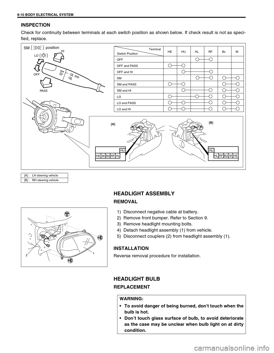
Check for continuity between terminals at each switch position as shown below. If check result is not as speci-
fied, replace.
HEADLIGHT ASSEMBLY
REMOVAL
1) Disconnect negative cable at battery.
2) Remove front bumper. Refer to Section 9.
3) Remove headlight mounting bolts.
4) Detach headlight assembly (1) from vehicle.
5) Disconnect couplers (2) from headlight assembly (1).
INSTALLATION
Reverse removal procedure for installation.
HEADLIGHT BULB
REPLACEMENT
[A] : LH steering vehicle
[B] : RH steering vehicle
HISMposition
PASS OFFLO
[B]
HU
HL RF B2 M HE [A]
HUHL
RF B2 M HE
Switch PositionTerminal
OFF
OFF and PASS
OFF and HI
SM
SM and PASS
SM and HI
LO
LO and PASS
LO and HIHE HU HL RF B2M
21
WARNING:
To avoid danger of being burned, don't touch when the
bulb is hot.
Don’t touch glass surface of bulb, to avoid deteriorate
as the case may be unclear when bulb light on at dirty
condition.
Page 256 of 447
8-12 BODY ELECTRICAL SYSTEM
HEADLIGHT LEVELING SWITCH (IF EQUIPPED)
INSPECTION
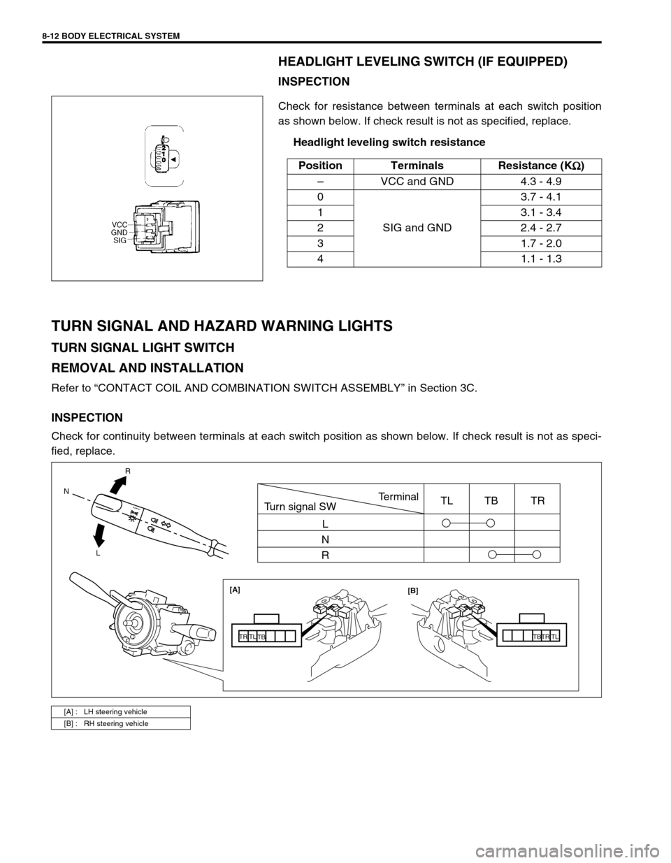
Check for resistance between terminals at each switch position
as shown below. If check result is not as specified, replace.
Headlight leveling switch resistance
TURN SIGNAL AND HAZARD WARNING LIGHTS
TURN SIGNAL LIGHT SWITCH
REMOVAL AND INSTALLATION
Refer to “CONTACT COIL AND COMBINATION SWITCH ASSEMBLY” in Section 3C.
INSPECTION
Check for continuity between terminals at each switch position as shown below. If check result is not as speci-
fied, replace.Position Terminals Resistance (K
Ω
ΩΩ Ω)
–VCC and GND 4.3 - 4.9
0
SIG and GND3.7 - 4.1
1 3.1 - 3.4
2 2.4 - 2.7
3 1.7 - 2.0
4 1.1 - 1.3
[A] : LH steering vehicle
[B] : RH steering vehicle
R
L N
[A]
[B]
TB
TBTR TR
TL TL
Turn signal SWTerminal
L
N
RTL TB TR
Page 258 of 447
8-14 BODY ELECTRICAL SYSTEM
REAR FOG LIGHT (IF EQUIPPED)
REAR FOG LIGHT SWITCH
INSPECTION
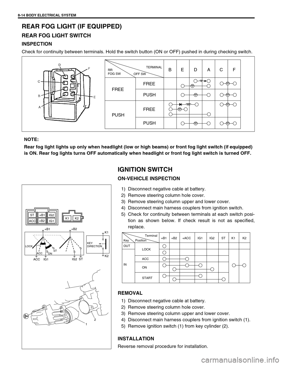
Check for continuity between terminals. Hold the switch button (ON or OFF) pushed in during checking switch.
IGNITION SWITCH
ON-VEHICLE INSPECTION
1) Disconnect negative cable at battery.
2) Remove steering column hole cover.
3) Remove steering column upper and lower cover.
4) Disconnect main harness couplers from ignition switch.
5) Check for continuity between terminals at each switch posi-
tion as shown below. If check result is not as specified,
replace.
REMOVAL
1) Disconnect negative cable at battery.
2) Remove steering column hole cover.
3) Remove steering column upper and lower cover.
4) Disconnect main harness couplers from ignition switch (1).
5) Remove ignition switch (1) from key cylinder (2).
INSTALLATION
Reverse removal procedure for installation.
RR
FOG SW
OFF SWTERMINAL
FREEFREE
PUSH
FREE
PUSH PUSHBE D AC F
NOTE:
Rear fog light lights up only when headlight (low or high beams) or front fog light switch (if equipped)
is ON. Rear fog lights turns OFF automatically when headlight or front fog light switch is turned OFF.
ST+B1
+B2
ACCIG2
IG1K1K2
+B1+B2
ACC IG1IG2STK1
K2
LOCK
ACC
ONSTKEY
DIRECTION
12
Position Key
OUT
LOCK
ACC
ON
START IN+B1 +B2 +ACC IG1 IG2 ST K1 K2 Terminal
Page 260 of 447
8-16 BODY ELECTRICAL SYSTEM
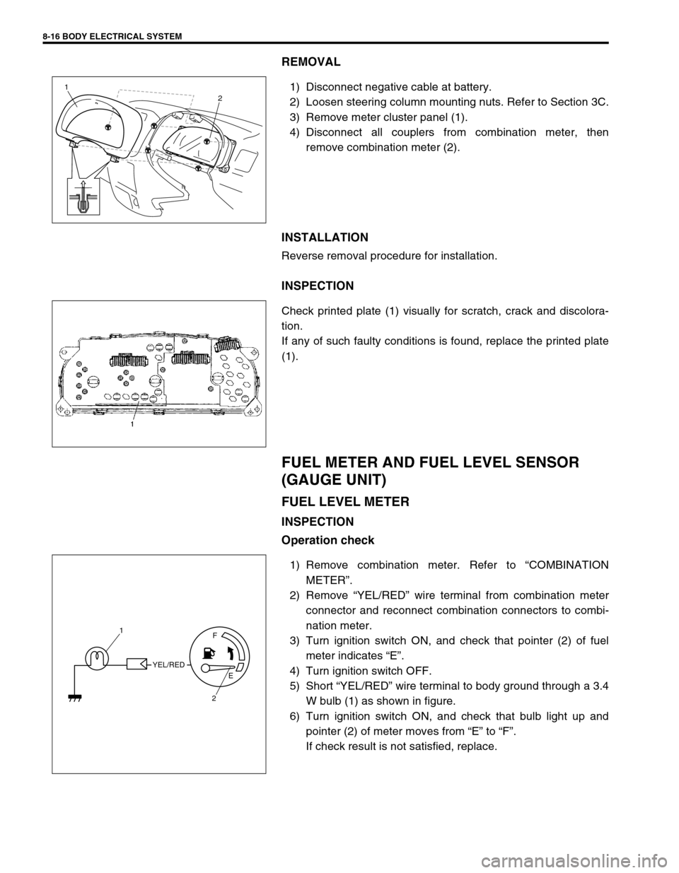
REMOVAL
1) Disconnect negative cable at battery.
2) Loosen steering column mounting nuts. Refer to Section 3C.
3) Remove meter cluster panel (1).
4) Disconnect all couplers from combination meter, then
remove combination meter (2).
INSTALLATION
Reverse removal procedure for installation.
INSPECTION
Check printed plate (1) visually for scratch, crack and discolora-
tion.
If any of such faulty conditions is found, replace the printed plate
(1).
FUEL METER AND FUEL LEVEL SENSOR
(GAUGE UNIT)
FUEL LEVEL METER
INSPECTION
Operation check
1) Remove combination meter. Refer to “COMBINATION
METER”.
2) Remove “YEL/RED” wire terminal from combination meter
connector and reconnect combination connectors to combi-
nation meter.
3) Turn ignition switch ON, and check that pointer (2) of fuel
meter indicates “E”.
4) Turn ignition switch OFF.
5) Short “YEL/RED” wire terminal to body ground through a 3.4
W bulb (1) as shown in figure.
6) Turn ignition switch ON, and check that bulb light up and
pointer (2) of meter moves from “E” to “F”.
If check result is not satisfied, replace.
1
2
YEL/REDF
E
2 1
Page 265 of 447
![SUZUKI SWIFT 2000 1.G Transmission Service Workshop Manual BODY ELECTRICAL SYSTEM 8-21
WIPERS AND WASHERS
COMPONENTS
FRONT WIPER AND WASHER SWITCH
REMOVAL AND INSTALLATION
Refer to “CONTACT COIL AND COMBINATION SWITCH
ASSEMBLY” in Section 3C.
[A] : RH ste SUZUKI SWIFT 2000 1.G Transmission Service Workshop Manual BODY ELECTRICAL SYSTEM 8-21
WIPERS AND WASHERS
COMPONENTS
FRONT WIPER AND WASHER SWITCH
REMOVAL AND INSTALLATION
Refer to “CONTACT COIL AND COMBINATION SWITCH
ASSEMBLY” in Section 3C.
[A] : RH ste](/img/20/7605/w960_7605-264.png)
BODY ELECTRICAL SYSTEM 8-21
WIPERS AND WASHERS
COMPONENTS
FRONT WIPER AND WASHER SWITCH
REMOVAL AND INSTALLATION
Refer to “CONTACT COIL AND COMBINATION SWITCH
ASSEMBLY” in Section 3C.
[A] : RH steering vehicle 3. Wiper motor 7. Washer hose
[B] : LH steering vehicle 4. Washer pump (for front washer) 8. Washer nozzle
1. Wiper blade 5. Washer pump (for rear washer) 9. Wiper link
2. Wiper arm 6. Washer tank
Page 266 of 447
8-22 BODY ELECTRICAL SYSTEM
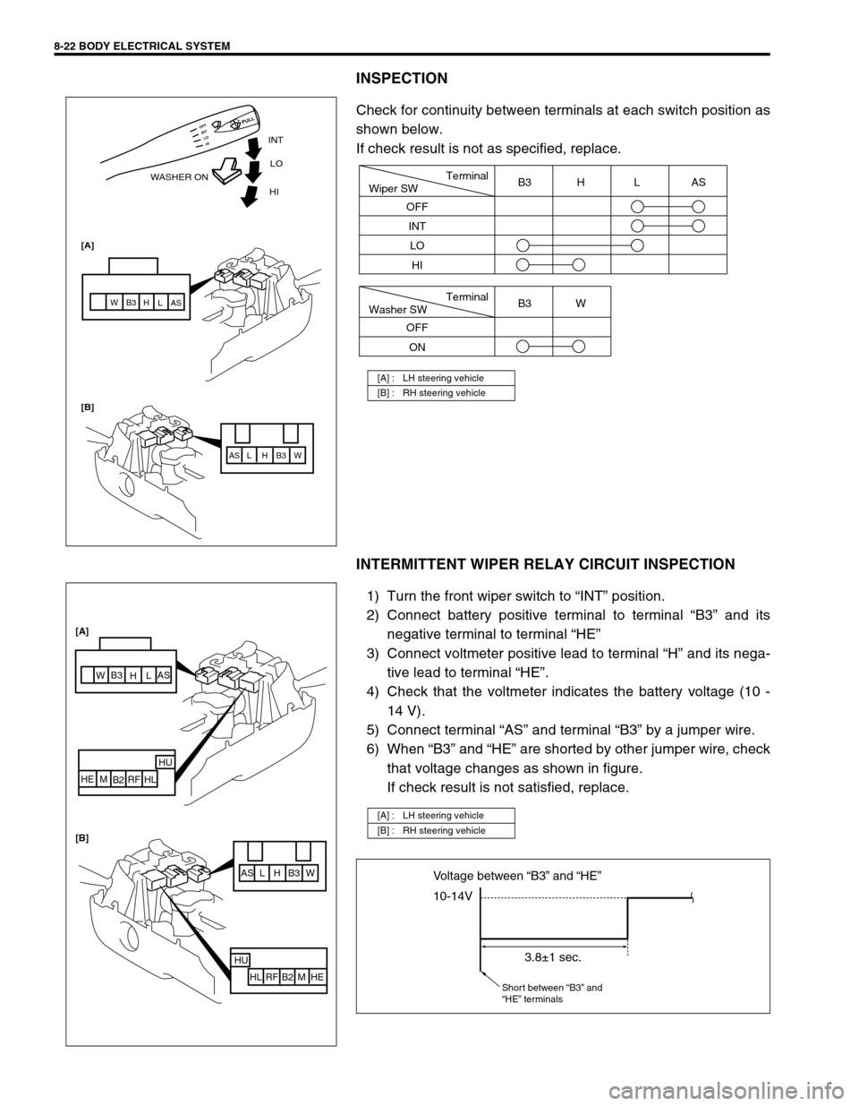
INSPECTION
Check for continuity between terminals at each switch position as
shown below.
If check result is not as specified, replace.
INTERMITTENT WIPER RELAY CIRCUIT INSPECTION
1) Turn the front wiper switch to “INT” position.
2) Connect battery positive terminal to terminal “B3” and its
negative terminal to terminal “HE”
3) Connect voltmeter positive lead to terminal “H” and its nega-
tive lead to terminal “HE”.
4) Check that the voltmeter indicates the battery voltage (10 -
14 V).
5) Connect terminal “AS” and terminal “B3” by a jumper wire.
6) When “B3” and “HE” are shorted by other jumper wire, check
that voltage changes as shown in figure.
If check result is not satisfied, replace.
[A] : LH steering vehicle
[B] : RH steering vehicle
INT
WASHER ONLO
[A]
[B]HI
AS AS
L L
H H
B3 B3
W W
HI LO INT OFF
PULL
Terminal
Wiper SW
OFF
INT
LOB3 H L AS
HI
Terminal
Washer SW
OFF
ONB3 W
[A] : LH steering vehicle
[B] : RH steering vehicle
AS L H B3 W
HU
HL RF B2 M HE
AS
L
H B3
W
HU
HL RF
B2 M HE [A]
[B]
10-14V Voltage between “B3” and “HE”
3.8±1 sec.
Short between “B3” and
“HE” terminals
Page 267 of 447
BODY ELECTRICAL SYSTEM 8-23
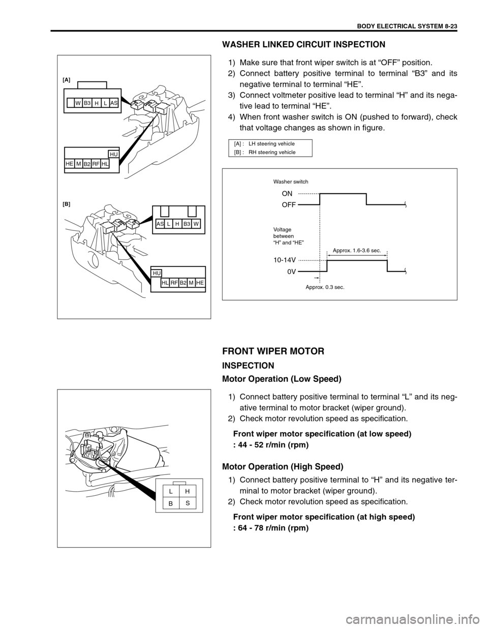
WASHER LINKED CIRCUIT INSPECTION
1) Make sure that front wiper switch is at “OFF” position.
2) Connect battery positive terminal to terminal “B3” and its
negative terminal to terminal “HE”.
3) Connect voltmeter positive lead to terminal “H” and its nega-
tive lead to terminal “HE”.
4) When front washer switch is ON (pushed to forward), check
that voltage changes as shown in figure.
FRONT WIPER MOTOR
INSPECTION
Motor Operation (Low Speed)
1) Connect battery positive terminal to terminal “L” and its neg-
ative terminal to motor bracket (wiper ground).
2) Check motor revolution speed as specification.
Front wiper motor specification (at low speed)
: 44 - 52 r/min (rpm)
Motor Operation (High Speed)
1) Connect battery positive terminal to “H” and its negative ter-
minal to motor bracket (wiper ground).
2) Check motor revolution speed as specification.
Front wiper motor specification (at high speed)
: 64 - 78 r/min (rpm)
[A] : LH steering vehicle
[B] : RH steering vehicle
AS L H B3 W
HU
HL RF B2 M HE
HU
HL RF
B2 M HE [A]
[B]
AS
L
H B3
W
10-14V
Washer switch
Voltage
between
“H” and “HE”
0V ON
OFF
Approx. 0.3 sec.Approx. 1.6-3.6 sec.
LH
S
B