window SUZUKI SWIFT 2000 1.G Transmission Service User Guide
[x] Cancel search | Manufacturer: SUZUKI, Model Year: 2000, Model line: SWIFT, Model: SUZUKI SWIFT 2000 1.GPages: 447, PDF Size: 10.54 MB
Page 308 of 447

9-4 BODY SERVICE
8) Remove outer weather-strip (1).
Lower window all the way down. Then, use a tape-wrapped
putty knife to pry off outer weather-strip.
9) Remove bottom channel attaching screws (1).
10) When removing door glass (2), turn door glass 90° counter-
clockwise to remove it.
INSTALLATION
Reverse removal procedure to install door glass noting the follow-
ing instructions.
If there is deformity for glass run, replace new one.
Tighten bottom channel attaching screws. Tighten rear
screw first, and then tighten front screw.
Glass fitted position of bottom channel (1) is as shown in fig-
ure.
Glass fitted position of bottom channel “a”
3-door model : 335.5 - 338.5 mm (13.21 - 13.33 in.)
5-door model : 90.8 - 93.8 mm (3.57 - 3.69 in.) NOTE:
When removed outer weather-strip (1) from door panel
(2), be careful not to deformation for outer weather-strip
(1).
12
2
2
1
Page 309 of 447

BODY SERVICE 9-5
Adjust equalizer (1) of window regular so that measurement
“a” and “b” are equal.
Secure door sealing cover (1) with adhesive (2).
Install door window regulator handle (1) so that it has a 45°
±12.5° angle when glass is fully closed as shown in figure
1 “a”“b”
1
2
A : Front
Page 310 of 447

9-6 BODY SERVICE
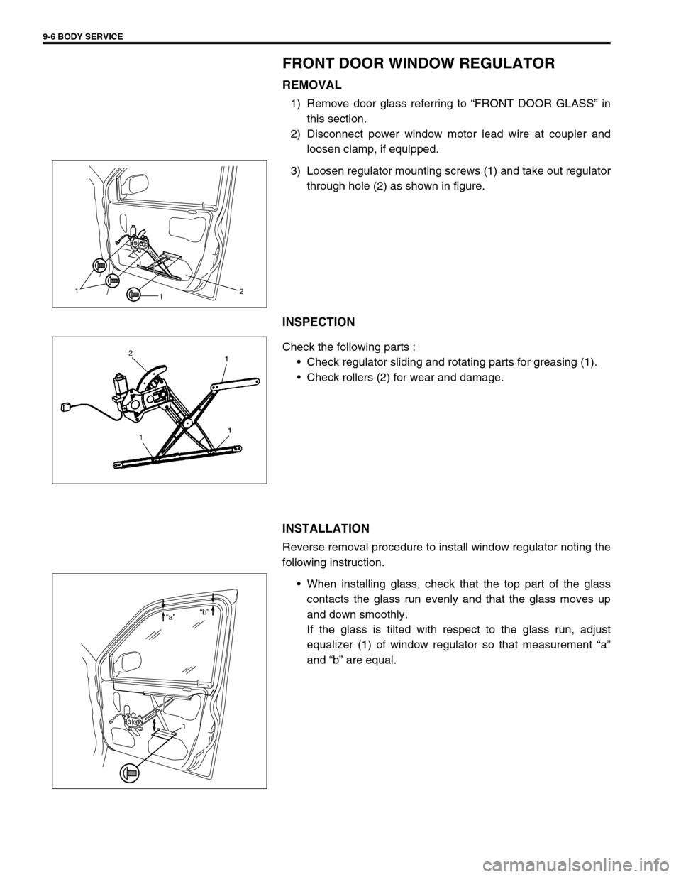
FRONT DOOR WINDOW REGULATOR
REMOVAL
1) Remove door glass referring to “FRONT DOOR GLASS” in
this section.
2) Disconnect power window motor lead wire at coupler and
loosen clamp, if equipped.
3) Loosen regulator mounting screws (1) and take out regulator
through hole (2) as shown in figure.
INSPECTION
Check the following parts :
Check regulator sliding and rotating parts for greasing (1).
Check rollers (2) for wear and damage.
INSTALLATION
Reverse removal procedure to install window regulator noting the
following instruction.
When installing glass, check that the top part of the glass
contacts the glass run evenly and that the glass moves up
and down smoothly.
If the glass is tilted with respect to the glass run, adjust
equalizer (1) of window regulator so that measurement “a”
and “b” are equal.
1
12
1 “a”“b”
Page 312 of 447

9-8 BODY SERVICE
REAR DOOR GLASS (IF EQUIPPED)
1. Door glass 7. Window regulator handle 13. Glass bottom rubber
2. Window regulator assembly
: Apply lithium grease 99000-25010 to moving section.8. Rear door outer weather-strip 14. Door inside pull handle case
3. Glass run 9. Rear door inside pull handle bracket [A] : Without power window model
4. Door trim 10. Rear door inner garnish [B] : With power window model
5. Door sealing cover 11. Rear door outer garnish
6. Door sash 12. Glass bottom channel
Page 313 of 447

BODY SERVICE 9-9
REMOVAL
1) Remove window regulator handle (1) (if equipped).
For its removal, pull off snap by using a cloth (2) as shown in
figure.
2) Remove inside handle bezel (1).
3) Remove door inside pull handle case fitting screw.
4) Remove rear door inner garnish.
5) Remove door trim (1).
With inside handle bezel (2) tilted as shown in figure, turn
door trim 90° counterclockwise to remove it.
And disconnect power window switch lead wire at coupler (if
equipped).
6) Remove door inside pull handle bracket.
7) Remove door sealing cover (1).
2
1
1
Page 314 of 447

9-10 BODY SERVICE
8) Remove rear door outer garnish (1).
9) Remove outer weather-strip (2).
Lower window all the way down. Then, use a tape-wrapped
putty knife (or screwdriver) to pry off outer weather-strip.
10) Detach rear part of glass run (1) from sash (2) and remove
sash (2) by removing 2 screws (3).
11) Loosen window regulator mounting screws (5).
12) When removing door glass (4), turn door glass 90° counter-
clockwise to remove it.
INSTALLATION
Reverse removal procedure to install door glass noting the follow-
ing instructions.
If there is deformity for glass run, replace new one.
Tighten bottom channel attaching screws. Tighten rear
screw first, and then tighten front screw.
Glass fitted position of bottom channel (1) is as shown in fig-
ure.
Glass fitted position of bottom channel
“a” : 201.9 - 204.9 mm (7.95 - 8.07 in.)
Secure door sealing cover (1) with adhesive (2). NOTE:
When removed outer weather-strip (2) from door panel
(3), be careful not to deformation for outer weather-strip
(2).
2 3
1
4
1
23
5
4
1
2
Page 315 of 447

BODY SERVICE 9-11
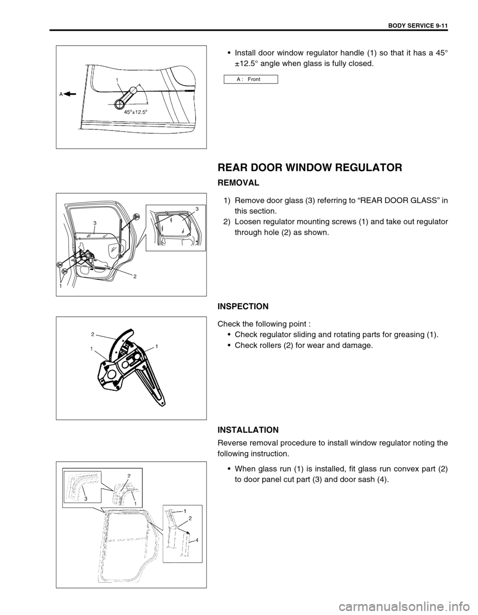
Install door window regulator handle (1) so that it has a 45°
±12.5° angle when glass is fully closed.
REAR DOOR WINDOW REGULATOR
REMOVAL
1) Remove door glass (3) referring to “REAR DOOR GLASS” in
this section.
2) Loosen regulator mounting screws (1) and take out regulator
through hole (2) as shown.
INSPECTION
Check the following point :
Check regulator sliding and rotating parts for greasing (1).
Check rollers (2) for wear and damage.
INSTALLATION
Reverse removal procedure to install window regulator noting the
following instruction.
When glass run (1) is installed, fit glass run convex part (2)
to door panel cut part (3) and door sash (4).
A : Front
3
3
2
1
Page 316 of 447

9-12 BODY SERVICE
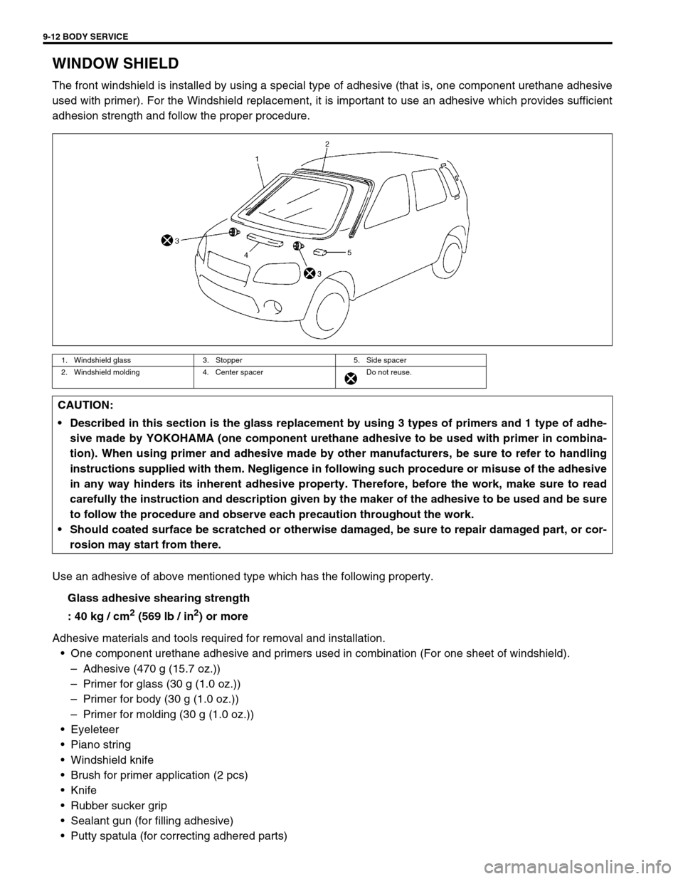
WINDOW SHIELD
The front windshield is installed by using a special type of adhesive (that is, one component urethane adhesive
used with primer). For the Windshield replacement, it is important to use an adhesive which provides sufficient
adhesion strength and follow the proper procedure.
Use an adhesive of above mentioned type which has the following property.
Glass adhesive shearing strength
: 40 kg / cm
2 (569 lb / in2) or more
Adhesive materials and tools required for removal and installation.
One component urethane adhesive and primers used in combination (For one sheet of windshield).
–Adhesive (470 g (15.7 oz.))
–Primer for glass (30 g (1.0 oz.))
–Primer for body (30 g (1.0 oz.))
–Primer for molding (30 g (1.0 oz.))
Eyeleteer
Piano string
Windshield knife
Brush for primer application (2 pcs)
Knife
Rubber sucker grip
Sealant gun (for filling adhesive)
Putty spatula (for correcting adhered parts)
1. Windshield glass 3. Stopper 5. Side spacer
2. Windshield molding 4. Center spacer Do not reuse.
CAUTION:
Described in this section is the glass replacement by using 3 types of primers and 1 type of adhe-
sive made by YOKOHAMA (one component urethane adhesive to be used with primer in combina-
tion). When using primer and adhesive made by other manufacturers, be sure to refer to handling
instructions supplied with them. Negligence in following such procedure or misuse of the adhesive
in any way hinders its inherent adhesive property. Therefore, before the work, make sure to read
carefully the instruction and description given by the maker of the adhesive to be used and be sure
to follow the procedure and observe each precaution throughout the work.
Should coated surface be scratched or otherwise damaged, be sure to repair damaged part, or cor-
rosion may start from there.
Page 321 of 447

BODY SERVICE 9-17
QUARTER WINDOW
REMOVAL AND INSTALLATION
Refer to “WINDSHIELD” in this section as removal and installa-
tion procedures are basically the same. However, note the follow-
ing.
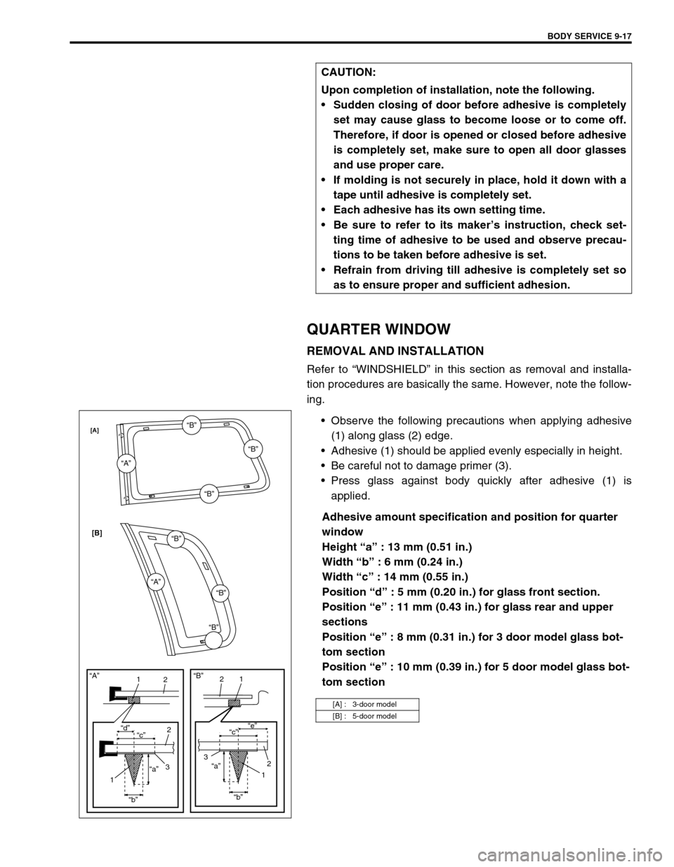
Observe the following precautions when applying adhesive
(1) along glass (2) edge.
Adhesive (1) should be applied evenly especially in height.
Be careful not to damage primer (3).
Press glass against body quickly after adhesive (1) is
applied.
Adhesive amount specification and position for quarter
window
Height “a” : 13 mm (0.51 in.)
Width “b” : 6 mm (0.24 in.)
Width “c” : 14 mm (0.55 in.)
Position “d” : 5 mm (0.20 in.) for glass front section.
Position “e” : 11 mm (0.43 in.) for glass rear and upper
sections
Position “e” : 8 mm (0.31 in.) for 3 door model glass bot-
tom section
Position “e” : 10 mm (0.39 in.) for 5 door model glass bot-
tom section CAUTION:
Upon completion of installation, note the following.
Sudden closing of door before adhesive is completely
set may cause glass to become loose or to come off.
Therefore, if door is opened or closed before adhesive
is completely set, make sure to open all door glasses
and use proper care.
If molding is not securely in place, hold it down with a
tape until adhesive is completely set.
Each adhesive has its own setting time.
Be sure to refer to its maker’s instruction, check set-
ting time of adhesive to be used and observe precau-
tions to be taken before adhesive is set.
Refrain from driving till adhesive is completely set so
as to ensure proper and sufficient adhesion.
[A] : 3-door model
[B] : 5-door model
“A”
“A”“B”
“B”
“B”
“B”
“B”“B”
11
22
2
33 “d”
“c”“c”“e”
“a”“a”
“b”“b”
11
2 “A”“B”
[A]
[B]
Page 327 of 447

BODY SERVICE 9-23
BACK DOOR ASSEMBLY
REMOVAL
1) Remove back door trim (1).
2) Remove related section of head lining and quarter trim.
3) Disconnect back door harness connectors (2) and washer
hose (3).
4) Remove wire harness connectors inside back door.
5) Remove back door balancer (4) (first at its door side and next
at its body side).
6) Remove door hinge nuts (5) and remove back door assembly
(6).
1. Back door panel assembly 4. Back door balancer unit
2. Back door window glass 5. Back door trim
3. Back door hinge
: Apply lithium grease 99000-25010 to door hinge moving section
: Apply sealant 99000-31110 to contact face6. Weather strip