wiring SUZUKI SWIFT 2000 1.G Transmission Service User Guide
[x] Cancel search | Manufacturer: SUZUKI, Model Year: 2000, Model line: SWIFT, Model: SUZUKI SWIFT 2000 1.GPages: 447, PDF Size: 10.54 MB
Page 250 of 447
8-6 BODY ELECTRICAL SYSTEM
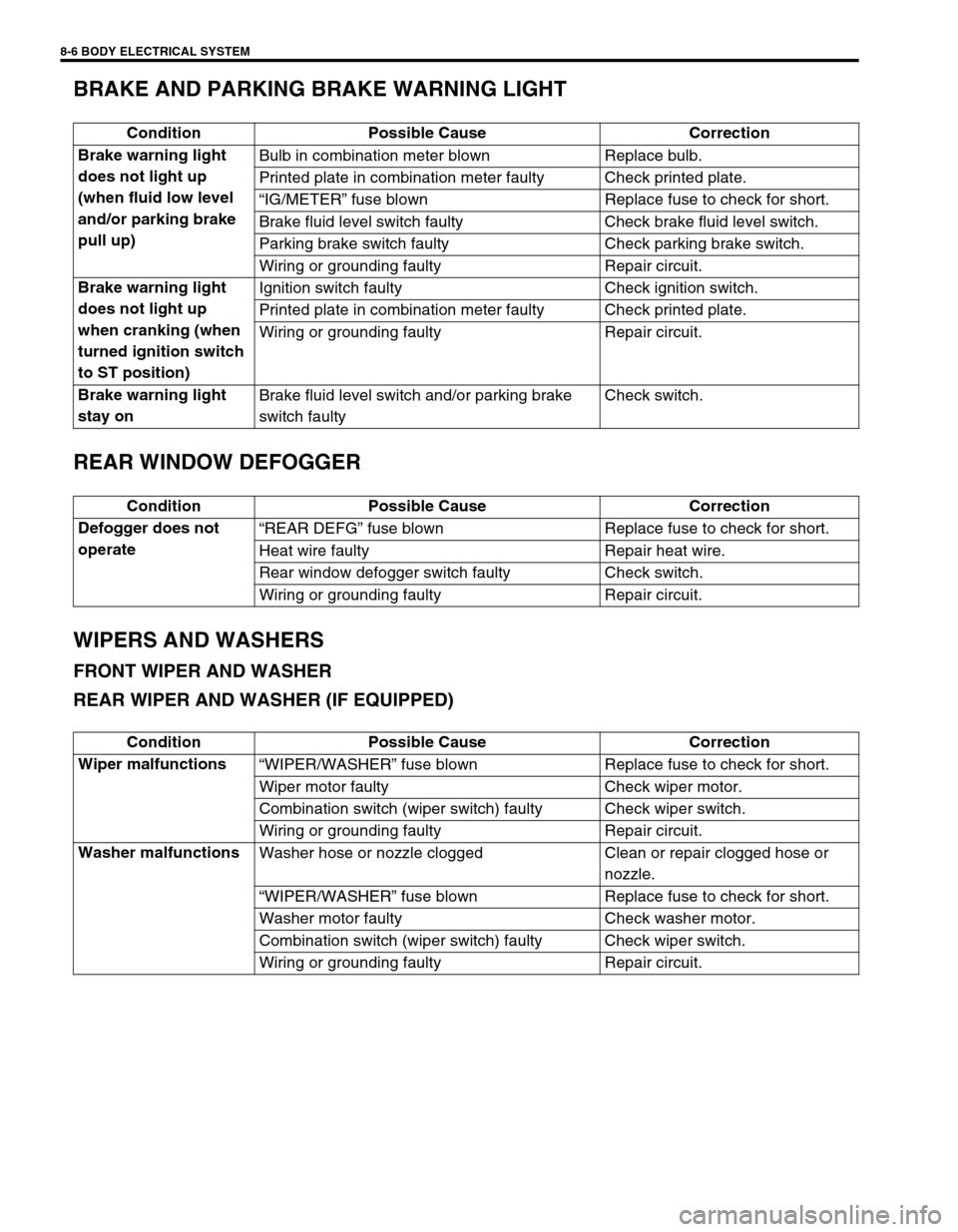
BRAKE AND PARKING BRAKE WARNING LIGHT
REAR WINDOW DEFOGGER
WIPERS AND WASHERS
FRONT WIPER AND WASHER
REAR WIPER AND WASHER (IF EQUIPPED)
Condition Possible Cause Correction
Brake warning light
does not light up
(when fluid low level
and/or parking brake
pull up)Bulb in combination meter blown Replace bulb.
Printed plate in combination meter faulty Check printed plate.
“IG/METER” fuse blown Replace fuse to check for short.
Brake fluid level switch faulty Check brake fluid level switch.
Parking brake switch faulty Check parking brake switch.
Wiring or grounding faulty Repair circuit.
Brake warning light
does not light up
when cranking (when
turned ignition switch
to ST position)Ignition switch faulty Check ignition switch.
Printed plate in combination meter faulty Check printed plate.
Wiring or grounding faulty Repair circuit.
Brake warning light
stay onBrake fluid level switch and/or parking brake
switch faultyCheck switch.
Condition Possible Cause Correction
Defogger does not
operate“REAR DEFG” fuse blown Replace fuse to check for short.
Heat wire faulty Repair heat wire.
Rear window defogger switch faulty Check switch.
Wiring or grounding faulty Repair circuit.
Condition Possible Cause Correction
Wiper malfunctions
“WIPER/WASHER” fuse blown Replace fuse to check for short.
Wiper motor faulty Check wiper motor.
Combination switch (wiper switch) faulty Check wiper switch.
Wiring or grounding faulty Repair circuit.
Washer malfunctions
Washer hose or nozzle clogged Clean or repair clogged hose or
nozzle.
“WIPER/WASHER” fuse blown Replace fuse to check for short.
Washer motor faulty Check washer motor.
Combination switch (wiper switch) faulty Check wiper switch.
Wiring or grounding faulty Repair circuit.
Page 251 of 447
BODY ELECTRICAL SYSTEM 8-7
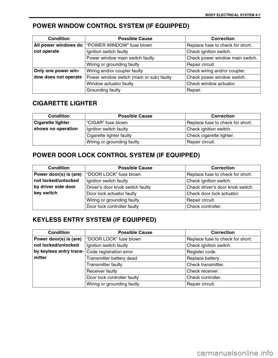
POWER WINDOW CONTROL SYSTEM (IF EQUIPPED)
CIGARETTE LIGHTER
POWER DOOR LOCK CONTROL SYSTEM (IF EQUIPPED)
KEYLESS ENTRY SYSTEM (IF EQUIPPED)
Condition Possible Cause Correction
All power windows do
not operate“POWER WINDOW” fuse blown Replace fuse to check for short.
Ignition switch faulty Check ignition switch.
Power window main switch faulty Check power window main switch.
Wiring or grounding faulty Repair circuit.
Only one power win-
dow does not operateWiring and/or coupler faulty Check wiring and/or coupler.
Power window switch (main or sub) faulty Check power window switch.
Window actuator faulty Check window actuator.
Grounding faulty Repair.
Condition Possible Cause Correction
Cigarette lighter
shows no operation“CIGAR” fuse blown Replace fuse to check for short.
Ignition switch faulty Check ignition switch.
Cigarette lighter faulty Check cigarette lighter.
Wiring or grounding faulty Repair circuit.
Condition Possible Cause Correction
Power door(s) is (are)
not locked/unlocked
by driver side door
key switch“DOOR LOCK” fuse blown Replace fuse to check for short.
Ignition switch faulty Check ignition switch.
Driver’s door knob switch faulty Check driver’s door knob switch.
Door lock actuator faulty Check door lock actuator.
Wiring or grounding faulty Repair circuit.
Door lock controller faulty Check controller.
Condition Possible Cause Correction
Power door(s) is (are)
not locked/unlocked
by keyless entry trans-
mitter“DOOR LOCK” fuse blown Replace fuse to check for short.
Ignition switch faulty Check ignition switch.
Code registration error Register code.
Transmitter battery dead Replace battery.
Transmitter faulty Check transmitter.
Receiver faulty Check receiver.
Door lock controller faulty Check controller.
Wiring or grounding faulty Repair circuit.
Page 252 of 447
8-8 BODY ELECTRICAL SYSTEM
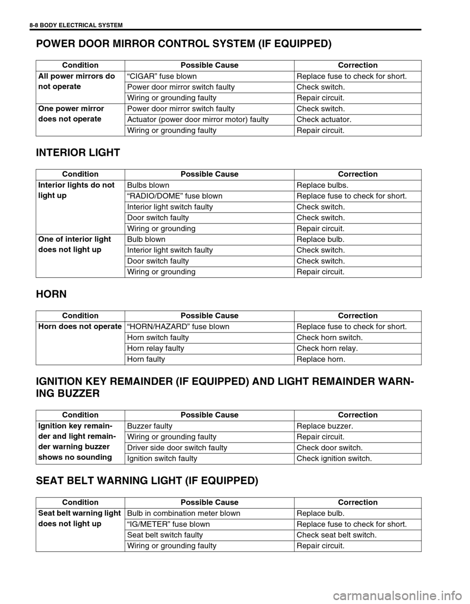
POWER DOOR MIRROR CONTROL SYSTEM (IF EQUIPPED)
INTERIOR LIGHT
HORN
IGNITION KEY REMAINDER (IF EQUIPPED) AND LIGHT REMAINDER WARN-
ING BUZZER
SEAT BELT WARNING LIGHT (IF EQUIPPED)
Condition Possible Cause Correction
All power mirrors do
not operate“CIGAR” fuse blown Replace fuse to check for short.
Power door mirror switch faulty Check switch.
Wiring or grounding faulty Repair circuit.
One power mirror
does not operatePower door mirror switch faulty Check switch.
Actuator (power door mirror motor) faulty Check actuator.
Wiring or grounding faulty Repair circuit.
Condition Possible Cause Correction
Interior lights do not
light upBulbs blown Replace bulbs.
“RADIO/DOME” fuse blown Replace fuse to check for short.
Interior light switch faulty Check switch.
Door switch faulty Check switch.
Wiring or grounding Repair circuit.
One of interior light
does not light upBulb blown Replace bulb.
Interior light switch faulty Check switch.
Door switch faulty Check switch.
Wiring or grounding Repair circuit.
Condition Possible Cause Correction
Horn does not operate
“HORN/HAZARD” fuse blown Replace fuse to check for short.
Horn switch faulty Check horn switch.
Horn relay faulty Check horn relay.
Horn faulty Replace horn.
Condition Possible Cause Correction
Ignition key remain-
der and light remain-
der warning buzzer
shows no soundingBuzzer faulty Replace buzzer.
Wiring or grounding faulty Repair circuit.
Driver side door switch faulty Check door switch.
Ignition switch faulty Check ignition switch.
Condition Possible Cause Correction
Seat belt warning light
does not light upBulb in combination meter blown Replace bulb.
“IG/METER” fuse blown Replace fuse to check for short.
Seat belt switch faulty Check seat belt switch.
Wiring or grounding faulty Repair circuit.
Page 253 of 447

BODY ELECTRICAL SYSTEM 8-9
FRONT SEAT HEATER (IF EQUIPPED)
ON-VEHICLE SERVICE
CAUTIONS IN SERVICING
When performing works related to electric systems, observe the cautions described in GENERAL INFORMA-
TION (Section 0A) of this manual for the purpose of protection of electrical parts and prevention of a fire from
occurrence.
HEADLIGHT
HEADLIGHT SWITCH
REMOVAL AND INSTALLATION
Refer to “CONTACT COIL AND COMBINATION SWITCH ASSEMBLY” in Section 3C. Condition Possible Cause Correction
Both seat back and
cushion do not
become hot although
seat heater switch is
LO/HI position“SEAT HTR” fuse blown Replace fuse to check for short.
Seat heater switch faulty Check switch.
Seat heater circuit in seat back and/or seat
cushion faultyCheck heater front back and/or
heater front cushion.
Wiring or grounding faulty Repair circuit.
Only seat back does
not become hot
although seat heater
switch is HI positionSeat heater circuit in seat back faulty Check heater front back.
Seat heater switch faulty Check switch.
Wiring faulty Repair.
Only seat cushion
does not become hot
although seat heater
switch is HI positionSeat heater circuit in seat back and/or seat
cushion faultyCheck heater front back and/or
heater front cushion.
Seat heater switch faulty Check switch.
Wiring faulty Repair.
Page 279 of 447
IMMOBILIZER CONTROL SYSTEM 8G-1
6F1
6F2
6G
6H
6K
7A
7A1
7B1
7C1
7D
7E
7F
8A
8B
8C
8D
8G
9
10
10A
10B
SECTION 8G
IMMOBILIZER CONTROL SYSTEM
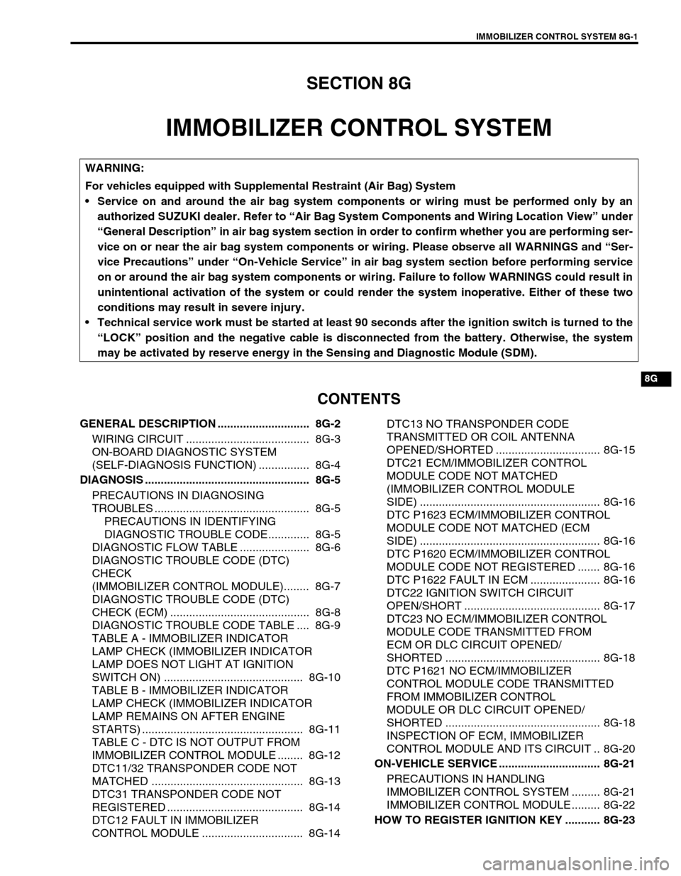
CONTENTS
GENERAL DESCRIPTION ............................. 8G-2
WIRING CIRCUIT ....................................... 8G-3
ON-BOARD DIAGNOSTIC SYSTEM
(SELF-DIAGNOSIS FUNCTION) ................ 8G-4
DIAGNOSIS .................................................... 8G-5
PRECAUTIONS IN DIAGNOSING
TROUBLES ................................................. 8G-5
PRECAUTIONS IN IDENTIFYING
DIAGNOSTIC TROUBLE CODE............. 8G-5
DIAGNOSTIC FLOW TABLE ...................... 8G-6
DIAGNOSTIC TROUBLE CODE (DTC)
CHECK
(IMMOBILIZER CONTROL MODULE)........ 8G-7
DIAGNOSTIC TROUBLE CODE (DTC)
CHECK (ECM) ............................................ 8G-8
DIAGNOSTIC TROUBLE CODE TABLE .... 8G-9
TABLE A - IMMOBILIZER INDICATOR
LAMP CHECK (IMMOBILIZER INDICATOR
LAMP DOES NOT LIGHT AT IGNITION
SWITCH ON) ............................................ 8G-10
TABLE B - IMMOBILIZER INDICATOR
LAMP CHECK (IMMOBILIZER INDICATOR
LAMP REMAINS ON AFTER ENGINE
STARTS) ................................................... 8G-11
TABLE C - DTC IS NOT OUTPUT FROM
IMMOBILIZER CONTROL MODULE ........ 8G-12
DTC11/32 TRANSPONDER CODE NOT
MATCHED ................................................ 8G-13
DTC31 TRANSPONDER CODE NOT
REGISTERED ........................................... 8G-14
DTC12 FAULT IN IMMOBILIZER
CONTROL MODULE ................................ 8G-14DTC13 NO TRANSPONDER CODE
TRANSMITTED OR COIL ANTENNA
OPENED/SHORTED ................................. 8G-15
DTC21 ECM/IMMOBILIZER CONTROL
MODULE CODE NOT MATCHED
(IMMOBILIZER CONTROL MODULE
SIDE) ......................................................... 8G-16
DTC P1623 ECM/IMMOBILIZER CONTROL
MODULE CODE NOT MATCHED (ECM
SIDE) ......................................................... 8G-16
DTC P1620 ECM/IMMOBILIZER CONTROL
MODULE CODE NOT REGISTERED ....... 8G-16
DTC P1622 FAULT IN ECM ...................... 8G-16
DTC22 IGNITION SWITCH CIRCUIT
OPEN/SHORT ........................................... 8G-17
DTC23 NO ECM/IMMOBILIZER CONTROL
MODULE CODE TRANSMITTED FROM
ECM OR DLC CIRCUIT OPENED/
SHORTED ................................................. 8G-18
DTC P1621 NO ECM/IMMOBILIZER
CONTROL MODULE CODE TRANSMITTED
FROM IMMOBILIZER CONTROL
MODULE OR DLC CIRCUIT OPENED/
SHORTED ................................................. 8G-18
INSPECTION OF ECM, IMMOBILIZER
CONTROL MODULE AND ITS CIRCUIT .. 8G-20
ON-VEHICLE SERVICE ................................ 8G-21
PRECAUTIONS IN HANDLING
IMMOBILIZER CONTROL SYSTEM ......... 8G-21
IMMOBILIZER CONTROL MODULE ......... 8G-22
HOW TO REGISTER IGNITION KEY ........... 8G-23 WARNING:
For vehicles equipped with Supplemental Restraint (Air Bag) System
Service on and around the air bag system components or wiring must be performed only by an
authorized SUZUKI dealer. Refer to “Air Bag System Components and Wiring Location View” under
“General Description” in air bag system section in order to confirm whether you are performing ser-
vice on or near the air bag system components or wiring. Please observe all WARNINGS and “Ser-
vice Precautions” under “On-Vehicle Service” in air bag system section before performing service
on or around the air bag system components or wiring. Failure to follow WARNINGS could result in
unintentional activation of the system or could render the system inoperative. Either of these two
conditions may result in severe injury.
Technical service work must be started at least 90 seconds after the ignition switch is turned to the
“LOCK” position and the negative cable is disconnected from the battery. Otherwise, the system
may be activated by reserve energy in the Sensing and Diagnostic Module (SDM).
Page 281 of 447

IMMOBILIZER CONTROL SYSTEM 8G-3
WIRING CIRCUIT
1. Immobilizer Control Module 4. Ignition switch 7. Data link connector
2. ECM 5. Fuse 8. To ABS control module, SDM and TCM
3. Main relay 6. Main fuse 9. Immobilizer indicator lamp
BRN/WHT
BLK/RED
BLK/WHT
PNK
BLK/RED
BLK/WHT
BLK
BLK
BLK/ORG
BLK/ORG
BLU
YEL
YEL
BLK/YEL
6
G02-7 G02-5
C42-2
C42-1
C42-3 C41-10
C41-5/6
G02-6
G02-12
G06-4
G06-3
G06-1G06-2
3
45 5
2
8
97
1
BB
BB
Page 288 of 447
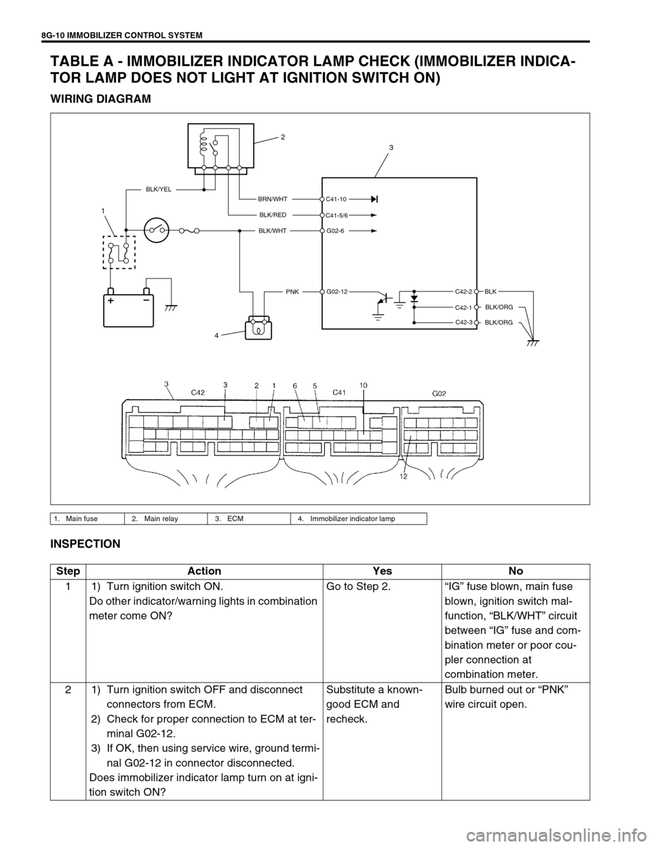
8G-10 IMMOBILIZER CONTROL SYSTEM
TABLE A - IMMOBILIZER INDICATOR LAMP CHECK (IMMOBILIZER INDICA-
TOR LAMP DOES NOT LIGHT AT IGNITION SWITCH ON)
WIRING DIAGRAM
INSPECTION
1. Main fuse 2. Main relay 3. ECM 4. Immobilizer indicator lamp
BRN/WHT
BLK/RED
BLK/WHT
PNKBLK
BLK/ORG
BLK/ORG
BLK/YEL
C42-2
C42-1
C42-3 C41-10
C41-5/6
G02-6
G02-12
4
1
2
3
Step Action Yes No
1 1) Turn ignition switch ON.
Do other indicator/warning lights in combination
meter come ON?Go to Step 2.“IG” fuse blown, main fuse
blown, ignition switch mal-
function, “BLK/WHT” circuit
between “IG” fuse and com-
bination meter or poor cou-
pler connection at
combination meter.
2 1) Turn ignition switch OFF and disconnect
connectors from ECM.
2) Check for proper connection to ECM at ter-
minal G02-12.
3) If OK, then using service wire, ground termi-
nal G02-12 in connector disconnected.
Does immobilizer indicator lamp turn on at igni-
tion switch ON?Substitute a known-
good ECM and
recheck.Bulb burned out or “PNK”
wire circuit open.
Page 289 of 447

IMMOBILIZER CONTROL SYSTEM 8G-11
TABLE B - IMMOBILIZER INDICATOR LAMP CHECK (IMMOBILIZER INDICA-
TOR LAMP REMAINS ON AFTER ENGINE STARTS)
WIRING DIAGRAM
INSPECTION
1. Main fuse 2. Main relay 3. ECM 4. Immobilizer indicator lamp
BRN/WHT
BLK/RED
BLK/WHT
PNKBLK
BLK/ORG
BLK/ORG
BLK/YEL
C42-2
C42-1
C42-3 C41-10
C41-5/6
G02-6
G02-12
4
1
2
3
Step Action Yes No
1 1) With ignition switch OFF, disconnect cou-
plers from ECM.
Does immobilizer indicator lamp turn ON at
ignition switch ON?“PNK” wire shorted to
ground circuit.Substitute a known-good
ECM and recheck.
Page 290 of 447

8G-12 IMMOBILIZER CONTROL SYSTEM
TABLE C - DTC IS NOT OUTPUT FROM IMMOBILIZER CONTROL MODULE
WIRING DIAGRAM
INSPECTION
1. To ECM 2. Immobilizer control module 3. To #9-pin in DLC
BLK/RED
BLK/WHTBLK/WHT
BLK
2
1
3
YEL
BLK/YEL
G06-4
G06-3
G06-1G06-2
Step Action Yes No
1 Check voltage between G06-4 terminal
and body ground with ignition switch
turned ON. See Fig 1.
Is it 10 – 14 V?Go to Step 2.“BLK/RED” wire
open or short to
ground.
2 1) Disconnect coupler (1) at immobilizer
control module.
Is there continuity between coupler termi-
nal G06-1 and body ground? See Fig 2.Poor G06-4 or G06-1 connection
Poor #9-pin connection in DLC
Serial data line “YEL” open or short
to ground
If connections and line are OK, substi-
tute a known-good Immobilizer Con-
trol Module and recheck.
See NOTE below.“BLK” wire open.
NOTE:
After replacing with a known-good Immobilizer Control Module, register ECM/Immobilizer Control
Module code in ECM and Transponder code and ECM/Immobilizer Control Module code in Immobilizer
Control Module by performing procedure described in “PROCEDURE AFTER IMMOBILIZER CON-
TROL MODULE REPLACEMENT” in this section.
Page 296 of 447

8G-18 IMMOBILIZER CONTROL SYSTEM
DTC23 NO ECM/IMMOBILIZER CONTROL MODULE CODE TRANSMITTED
FROM ECM OR DLC CIRCUIT OPENED/SHORTED
DTC P1621 NO ECM/IMMOBILIZER CONTROL MODULE CODE TRANSMITTED
FROM IMMOBILIZER CONTROL MODULE OR DLC CIRCUIT OPENED/
SHORTED
DESCRIPTION
When the ignition switch is ON, Immobilizer Control Module requests ECM and ECM requests Immobilizer Con-
trol Module to transmit ECM/Immobilizer Control Module code. If ECM/Immobilizer Control Module code is not
transmitted from ECM or Immobilizer Control Module, Immobilizer Control Module sets DTC23 and ECM sets
DTC P1621.
INSPECTION
1. Immobilizer Control Module 2. ECM 3. To #9-pin in DLC
YEL G06-2G02-7YEL
YEL
1
32
Step Action Yes No
1 Check voltage between Immobilizer Con-
trol Module (1) coupler terminal G06-2
and body ground with ignition switch
turned ON.
Is it 4 – 5V?Go to Step 2.“YEL” wire short.
2 1) Disconnect ECM coupler with ignition
switch turned OFF.
2) Is there continuity between Immobi-
lizer Control Module coupler (1) termi-
nal G06-2 and serial data link terminal
(G02-7) of ECM coupler? (For posi-
tions of Data link connector terminal
of ECM coupler, refer to “WIRING
CIRCUIT” in this section.)Poor G06-2 terminal connection
(Immobilizer Control Module) or Poor
Data link connector terminal connec-
tion (ECM).
If connections are OK, substitute a
known-good ECM or Immobilizer Con-
trol Module and recheck.
See NOTE below.“YEL” wire between
Immobilizer Control
Module and ECM
open.