ECU SUZUKI SWIFT 2000 1.G Transmission Service Workshop Manual
[x] Cancel search | Manufacturer: SUZUKI, Model Year: 2000, Model line: SWIFT, Model: SUZUKI SWIFT 2000 1.GPages: 447, PDF Size: 10.54 MB
Page 14 of 447
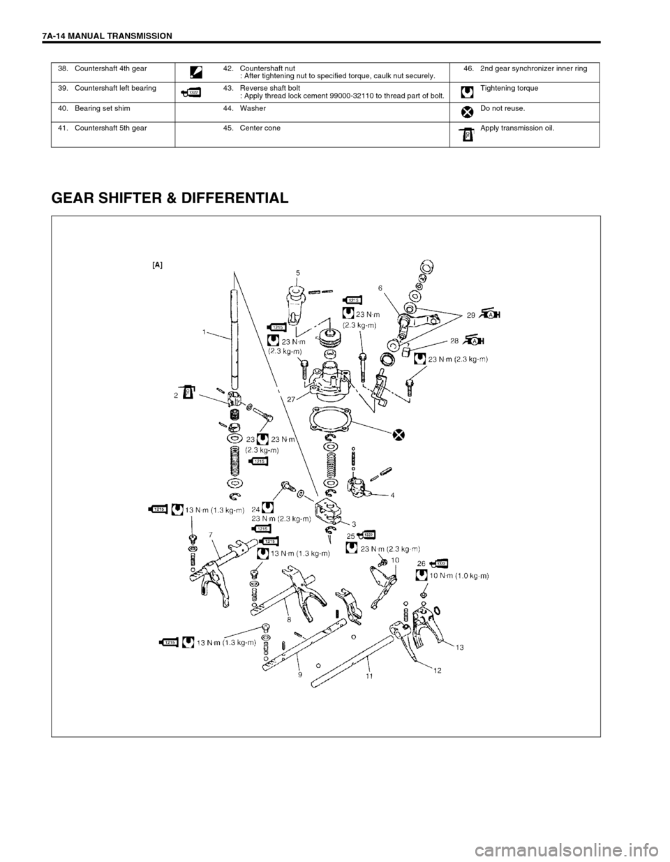
7A-14 MANUAL TRANSMISSION
GEAR SHIFTER & DIFFERENTIAL
38. Countershaft 4th gear 42. Countershaft nut
: After tightening nut to specified torque, caulk nut securely.46. 2nd gear synchronizer inner ring
39. Countershaft left bearing 43. Reverse shaft bolt
: Apply thread lock cement 99000-32110 to thread part of bolt.Tightening torque
40. Bearing set shim 44. Washer Do not reuse.
41. Countershaft 5th gear 45. Center cone Apply transmission oil.
Page 17 of 447
MANUAL TRANSMISSION 7A-17
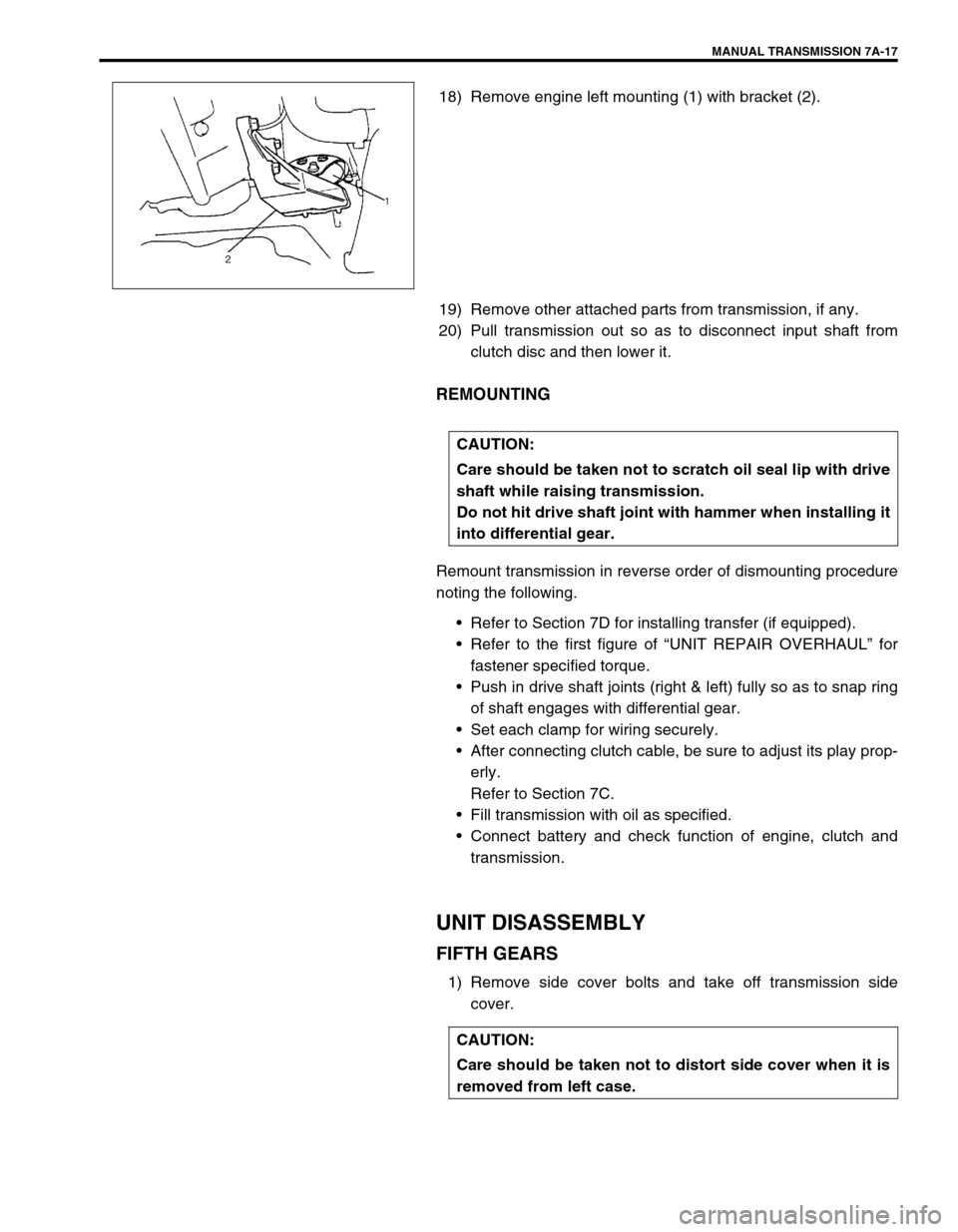
18) Remove engine left mounting (1) with bracket (2).
19) Remove other attached parts from transmission, if any.
20) Pull transmission out so as to disconnect input shaft from
clutch disc and then lower it.
REMOUNTING
Remount transmission in reverse order of dismounting procedure
noting the following.
Refer to Section 7D for installing transfer (if equipped).
Refer to the first figure of “UNIT REPAIR OVERHAUL” for
fastener specified torque.
Push in drive shaft joints (right & left) fully so as to snap ring
of shaft engages with differential gear.
Set each clamp for wiring securely.
After connecting clutch cable, be sure to adjust its play prop-
erly.
Refer to Section 7C.
Fill transmission with oil as specified.
Connect battery and check function of engine, clutch and
transmission.
UNIT DISASSEMBLY
FIFTH GEARS
1) Remove side cover bolts and take off transmission side
cover.
CAUTION:
Care should be taken not to scratch oil seal lip with drive
shaft while raising transmission.
Do not hit drive shaft joint with hammer when installing it
into differential gear.
CAUTION:
Care should be taken not to distort side cover when it is
removed from left case.
Page 24 of 447
7A-24 MANUAL TRANSMISSION
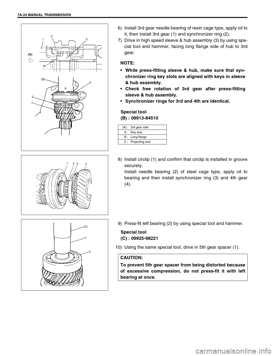
6) Install 3rd gear needle bearing of resin cage type, apply oil to
it, then install 3rd gear (1) and synchronizer ring (2).
7) Drive in high speed sleeve & hub assembly (3) by using spe-
cial tool and hammer, facing long flange side of hub to 3rd
gear.
Special tool
(B) : 09913-84510
8) Install circlip (1) and confirm that circlip is installed in groove
securely.
Install needle bearing (2) of steel cage type, apply oil to
bearing and then install synchronizer ring (3) and 4th gear
(4).
9) Press-fit left bearing (2) by using special tool and hammer.
Special tool
(C) : 09925-98221
10) Using the same special tool, drive in 5th gear spacer (1).NOTE:
While press-fitting sleeve & hub, make sure that syn-
chronizer ring key slots are aligned with keys in sleeve
& hub assembly.
Check free rotation of 3rd gear after press-fitting
sleeve & hub assembly.
Synchronizer rings for 3rd and 4th are identical.
[A] : 3rd gear side
A : Key way
B : Long flange
C : Projecting end
CAUTION:
To prevent 5th gear spacer from being distorted because
of excessive compression, do not press-fit it with left
bearing at once.
Page 28 of 447
7A-28 MANUAL TRANSMISSION
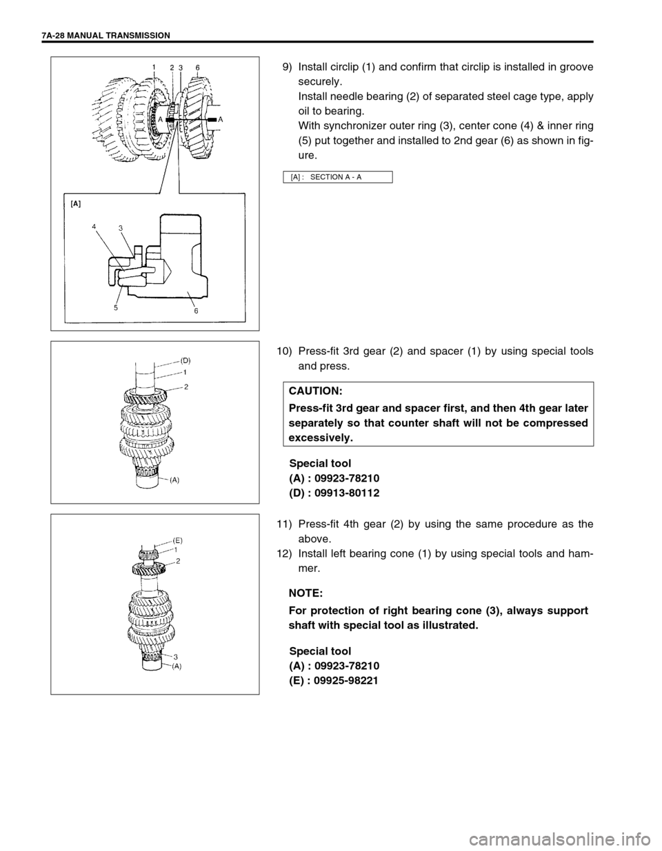
9) Install circlip (1) and confirm that circlip is installed in groove
securely.
Install needle bearing (2) of separated steel cage type, apply
oil to bearing.
With synchronizer outer ring (3), center cone (4) & inner ring
(5) put together and installed to 2nd gear (6) as shown in fig-
ure.
10) Press-fit 3rd gear (2) and spacer (1) by using special tools
and press.
Special tool
(A) : 09923-78210
(D) : 09913-80112
11) Press-fit 4th gear (2) by using the same procedure as the
above.
12) Install left bearing cone (1) by using special tools and ham-
mer.
Special tool
(A) : 09923-78210
(E) : 09925-98221
[A] : SECTION A - A
CAUTION:
Press-fit 3rd gear and spacer first, and then 4th gear later
separately so that counter shaft will not be compressed
excessively.
NOTE:
For protection of right bearing cone (3), always support
shaft with special tool as illustrated.
Page 37 of 447
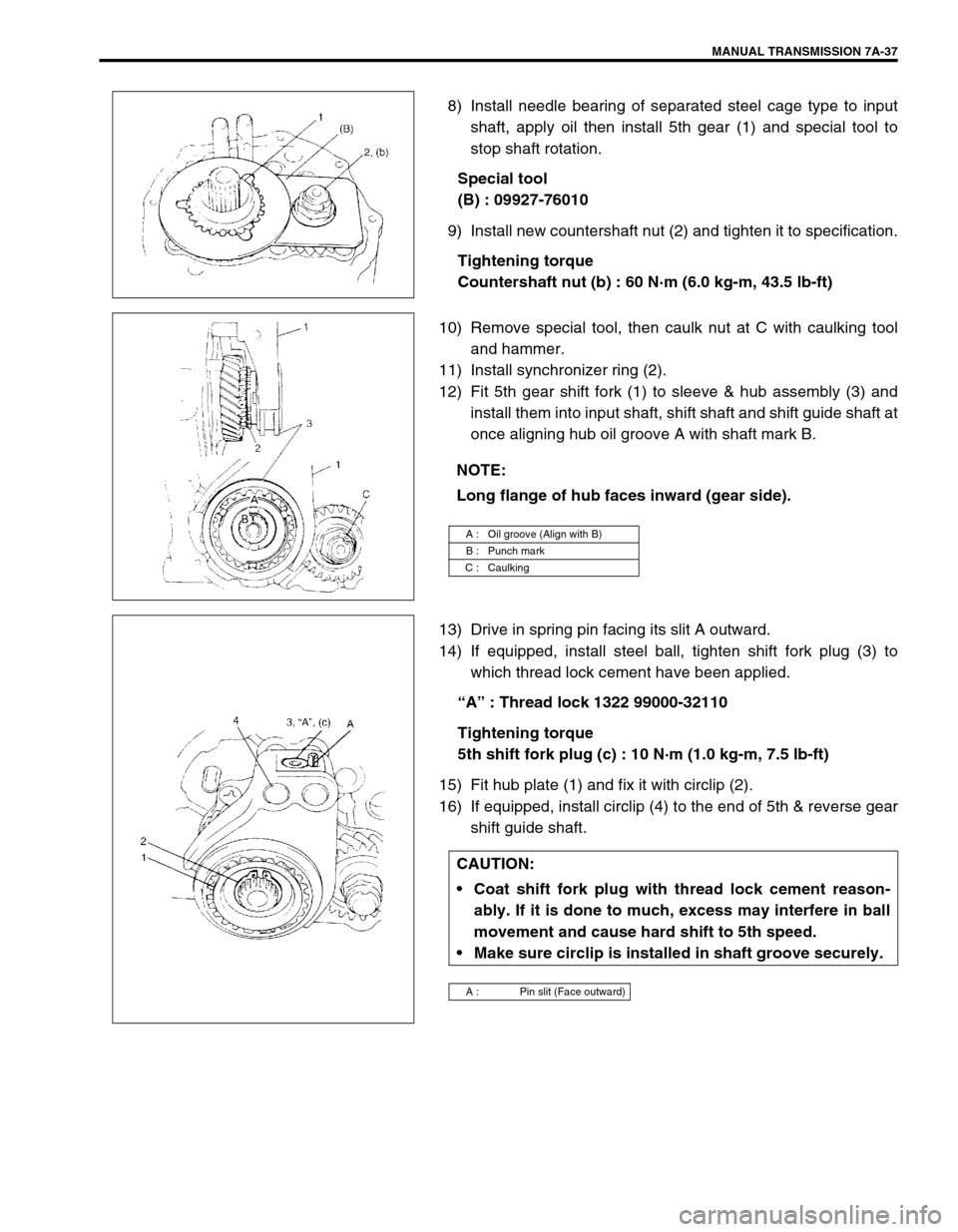
MANUAL TRANSMISSION 7A-37
8) Install needle bearing of separated steel cage type to input
shaft, apply oil then install 5th gear (1) and special tool to
stop shaft rotation.
Special tool
(B) : 09927-76010
9) Install new countershaft nut (2) and tighten it to specification.
Tightening torque
Countershaft nut (b) : 60 N·m (6.0 kg-m, 43.5 lb-ft)
10) Remove special tool, then caulk nut at C with caulking tool
and hammer.
11) Install synchronizer ring (2).
12) Fit 5th gear shift fork (1) to sleeve & hub assembly (3) and
install them into input shaft, shift shaft and shift guide shaft at
once aligning hub oil groove A with shaft mark B.
13) Drive in spring pin facing its slit A outward.
14) If equipped, install steel ball, tighten shift fork plug (3) to
which thread lock cement have been applied.
“A” : Thread lock 1322 99000-32110
Tightening torque
5th shift fork plug (c) : 10 N·m (1.0 kg-m, 7.5 lb-ft)
15) Fit hub plate (1) and fix it with circlip (2).
16) If equipped, install circlip (4) to the end of 5th & reverse gear
shift guide shaft.
NOTE:
Long flange of hub faces inward (gear side).
A : Oil groove (Align with B)
B : Punch mark
C : Caulking
CAUTION:
Coat shift fork plug with thread lock cement reason-
ably. If it is done to much, excess may interfere in ball
movement and cause hard shift to 5th speed.
Make sure circlip is installed in shaft groove securely.
A : Pin slit (Face outward)
Page 64 of 447
7B-22 AUTOMATIC TRANSMISSION (4 A/T)
LINE PRESSURE TEST
Purpose of this test is to check operating conditions of each part
by measuring fluid pressure in fluid pressure line.
Line pressure test requires following conditions.
Automatic fluid is at normal operating temperature (70 –
80°C /158 – 176°F).
Fluid is filled to proper level (between FULL and LOW on
dipstick).
1) Apply parking brake securely and place chocks against
wheels.
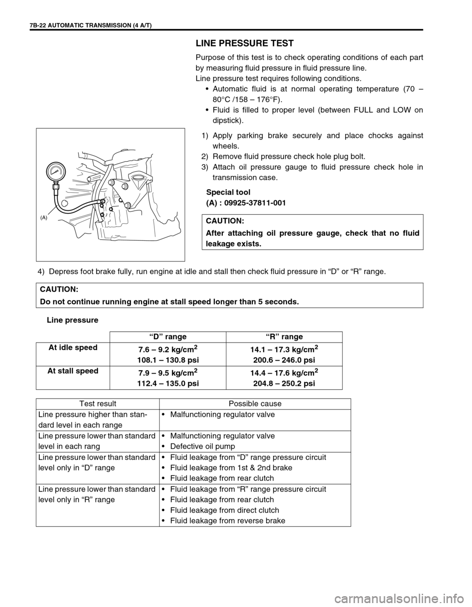
2) Remove fluid pressure check hole plug bolt.
3) Attach oil pressure gauge to fluid pressure check hole in
transmission case.
Special tool
(A) : 09925-37811-001
4) Depress foot brake fully, run engine at idle and stall then check fluid pressure in “D” or “R” range.
Line pressureCAUTION:
After attaching oil pressure gauge, check that no fluid
leakage exists.
(A)
CAUTION:
Do not continue running engine at stall speed longer than 5 seconds.
“D” range “R” range
At idle speed
7.6 – 9.2 kg/cm
2
108.1 – 130.8 psi14.1 – 17.3 kg/cm
2
200.6 – 246.0 psi
At stall speed
7.9 – 9.5 kg/cm
2
112.4 – 135.0 psi14.4 – 17.6 kg/cm
2
204.8 – 250.2 psi
Test result Possible cause
Line pressure higher than stan-
dard level in each rangeMalfunctioning regulator valve
Line pressure lower than standard
level in each rangMalfunctioning regulator valve
Defective oil pump
Line pressure lower than standard
level only in “D” rangeFluid leakage from “D” range pressure circuit
Fluid leakage from 1st & 2nd brake
Fluid leakage from rear clutch
Line pressure lower than standard
level only in “R” rangeFluid leakage from “R” range pressure circuit
Fluid leakage from rear clutch
Fluid leakage from direct clutch
Fluid leakage from reverse brake
Page 103 of 447
AUTOMATIC TRANSMISSION (4 A/T) 7B-61
ADJUSTMENT
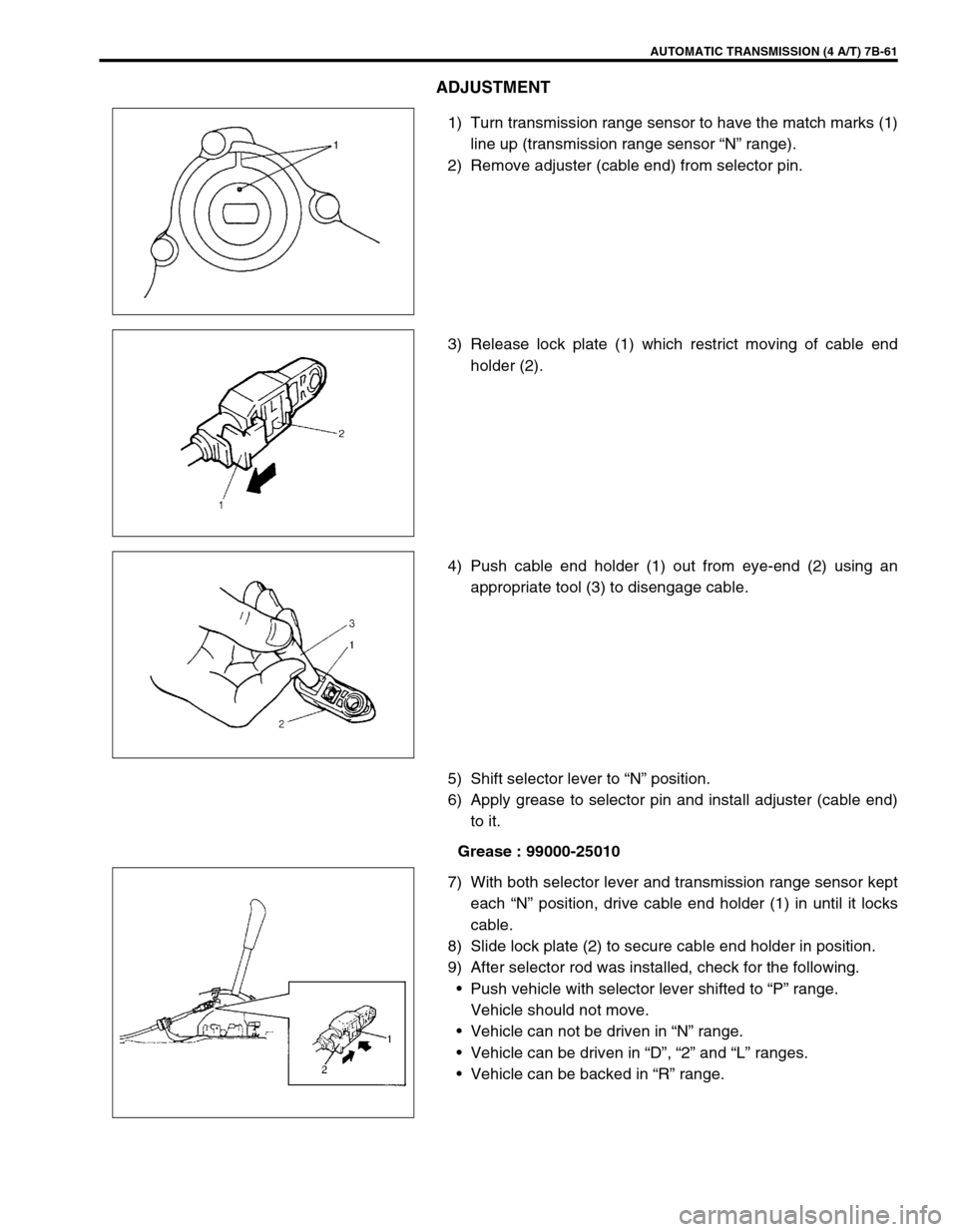
1) Turn transmission range sensor to have the match marks (1)
line up (transmission range sensor “N” range).
2) Remove adjuster (cable end) from selector pin.
3) Release lock plate (1) which restrict moving of cable end
holder (2).
4) Push cable end holder (1) out from eye-end (2) using an
appropriate tool (3) to disengage cable.
5) Shift selector lever to “N” position.
6) Apply grease to selector pin and install adjuster (cable end)
to it.
Grease : 99000-25010
7) With both selector lever and transmission range sensor kept
each “N” position, drive cable end holder (1) in until it locks
cable.
8) Slide lock plate (2) to secure cable end holder in position.
9) After selector rod was installed, check for the following.
Push vehicle with selector lever shifted to “P” range.
Vehicle should not move.
Vehicle can not be driven in “N” range.
Vehicle can be driven in “D”, “2” and “L” ranges.
Vehicle can be backed in “R” range.
Page 111 of 447
AUTOMATIC TRANSMISSION (4 A/T) 7B-69
TRANSMISSION CONTROL MODULE (TCM)
REMOVAL
1) Disconnect negative cable at battery.
2) If the vehicle is equipped with air bag system, disable air bag
system. Refer to “DISABLING AIR BAG SYSTEM” in Sec-
tion 10B.
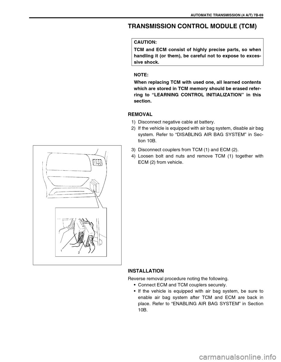
3) Disconnect couplers from TCM (1) and ECM (2).
4) Loosen bolt and nuts and remove TCM (1) together with
ECM (2) from vehicle.
INSTALLATION
Reverse removal procedure noting the following.
Connect ECM and TCM couplers securely.
If the vehicle is equipped with air bag system, be sure to
enable air bag system after TCM and ECM are back in
place. Refer to “ENABLING AIR BAG SYSTEM” in Section
10B. CAUTION:
TCM and ECM consist of highly precise parts, so when
handling it (or them), be careful not to expose to exces-
sive shock.
NOTE:
When replacing TCM with used one, all learned contents
which are stored in TCM memory should be erased refer-
ring to “LEARNING CONTROL INITIALIZATION” in this
section.
Page 115 of 447
AUTOMATIC TRANSMISSION (4 A/T) 7B-73
REMOVAL
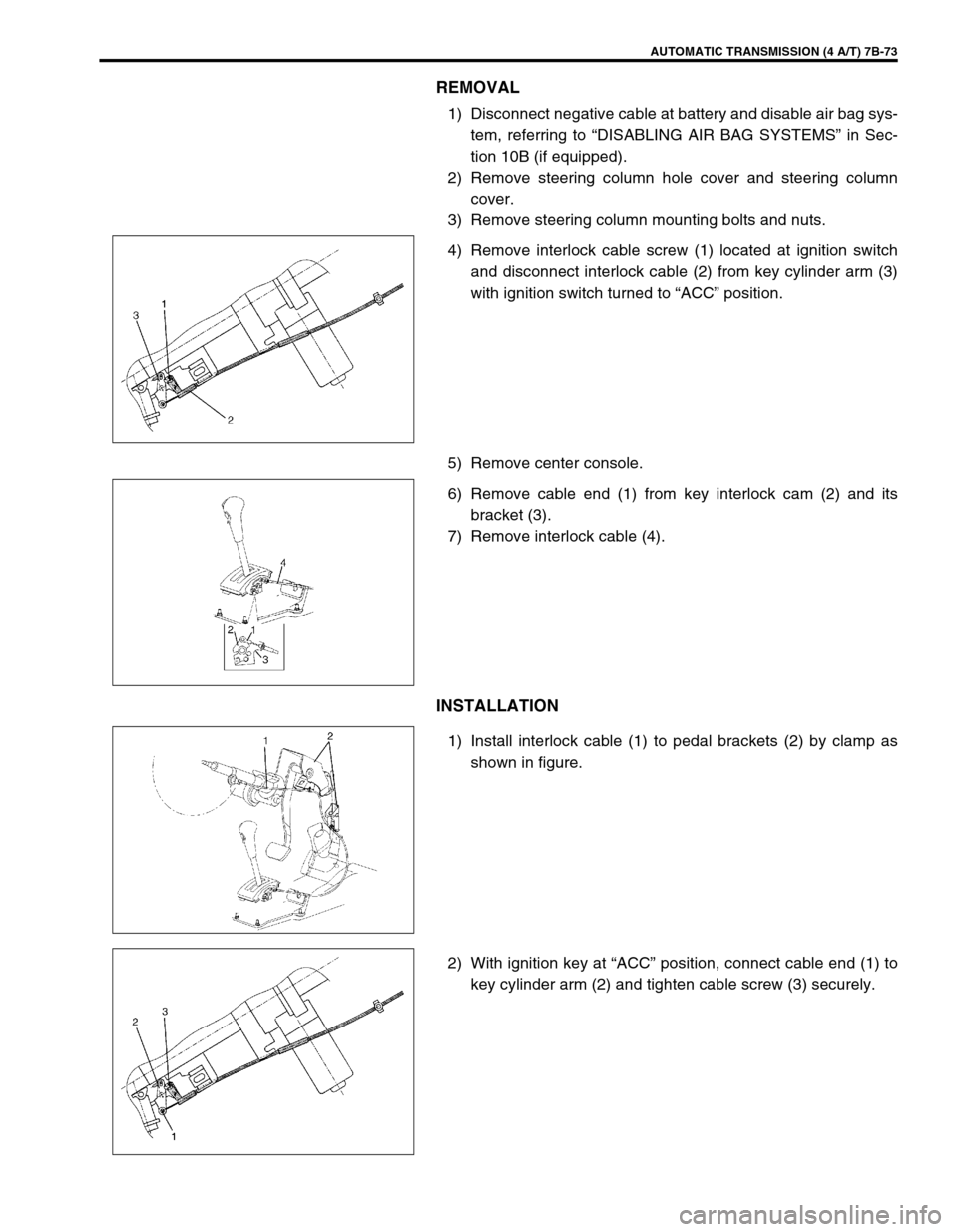
1) Disconnect negative cable at battery and disable air bag sys-
tem, referring to “DISABLING AIR BAG SYSTEMS” in Sec-
tion 10B (if equipped).
2) Remove steering column hole cover and steering column
cover.
3) Remove steering column mounting bolts and nuts.
4) Remove interlock cable screw (1) located at ignition switch
and disconnect interlock cable (2) from key cylinder arm (3)
with ignition switch turned to “ACC” position.
5) Remove center console.
6) Remove cable end (1) from key interlock cam (2) and its
bracket (3).
7) Remove interlock cable (4).
INSTALLATION
1) Install interlock cable (1) to pedal brackets (2) by clamp as
shown in figure.
2) With ignition key at “ACC” position, connect cable end (1) to
key cylinder arm (2) and tighten cable screw (3) securely.
Page 184 of 447
7C-2 CLUTCH
GENERAL DESCRIPTION
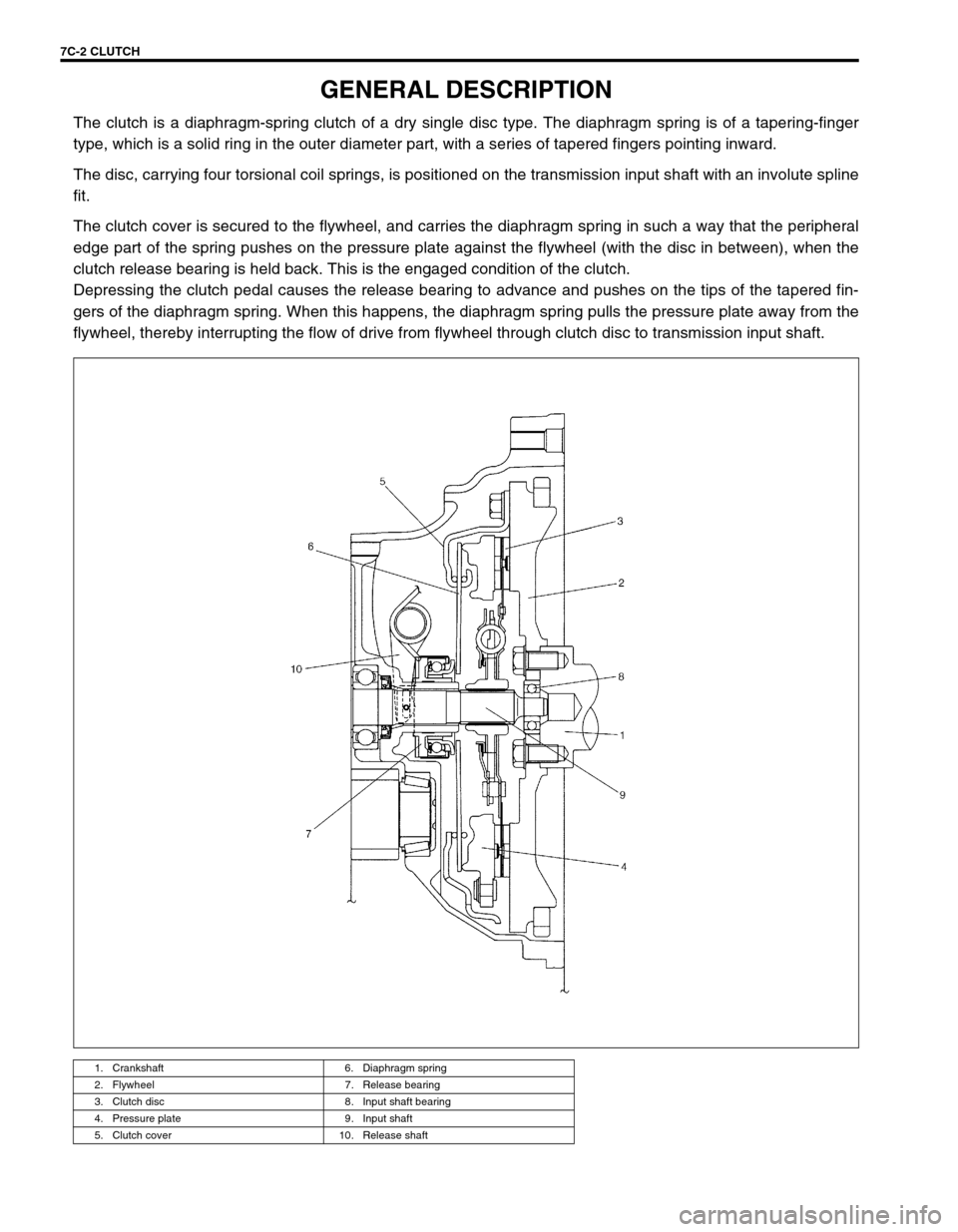
The clutch is a diaphragm-spring clutch of a dry single disc type. The diaphragm spring is of a tapering-finger
type, which is a solid ring in the outer diameter part, with a series of tapered fingers pointing inward.
The disc, carrying four torsional coil springs, is positioned on the transmission input shaft with an involute spline
fit.
The clutch cover is secured to the flywheel, and carries the diaphragm spring in such a way that the peripheral
edge part of the spring pushes on the pressure plate against the flywheel (with the disc in between), when the
clutch release bearing is held back. This is the engaged condition of the clutch.
Depressing the clutch pedal causes the release bearing to advance and pushes on the tips of the tapered fin-
gers of the diaphragm spring. When this happens, the diaphragm spring pulls the pressure plate away from the
flywheel, thereby interrupting the flow of drive from flywheel through clutch disc to transmission input shaft.
1. Crankshaft 6. Diaphragm spring
2. Flywheel 7. Release bearing
3. Clutch disc 8. Input shaft bearing
4. Pressure plate 9. Input shaft
5. Clutch cover 10. Release shaft