differential SUZUKI SWIFT 2000 1.G Transmission Service Owner's Manual
[x] Cancel search | Manufacturer: SUZUKI, Model Year: 2000, Model line: SWIFT, Model: SUZUKI SWIFT 2000 1.GPages: 447, PDF Size: 10.54 MB
Page 123 of 447

AUTOMATIC TRANSMISSION (4 A/T) 7B-81
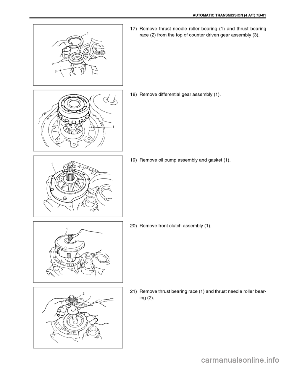
17) Remove thrust needle roller bearing (1) and thrust bearing
race (2) from the top of counter driven gear assembly (3).
18) Remove differential gear assembly (1).
19) Remove oil pump assembly and gasket (1).
20) Remove front clutch assembly (1).
21) Remove thrust bearing race (1) and thrust needle roller bear-
ing (2).
Page 154 of 447

7B-112 AUTOMATIC TRANSMISSION (4 A/T)
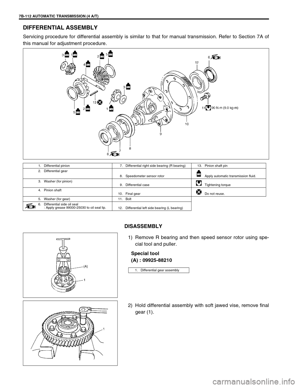
DIFFERENTIAL ASSEMBLY
Servicing procedure for differential assembly is similar to that for manual transmission. Refer to Section 7A of
this manual for adjustment procedure.
DISASSEMBLY
1) Remove R bearing and then speed sensor rotor using spe-
cial tool and puller.
Special tool
(A) : 09925-88210
2) Hold differential assembly with soft jawed vise, remove final
gear (1).
1. Differential pinion 7. Differential right side bearing (R bearing) 13. Pinion shaft pin
2. Differential gear
8. Speedometer sensor rotor Apply automatic transmission fluid.
3. Washer (for pinion)
9. Differential case Tightening torque
4. Pinion shaft
10. Final gear Do not reuse.
5. Washer (for gear) 11. Bolt
6. Differential side oil seal
: Apply grease 99000-25030 to oil seal lip.
12. Differential left side bearing (L bearing)
1. Differential gear assembly
Page 155 of 447

AUTOMATIC TRANSMISSION (4 A/T) 7B-113
3) Remove differential side L bearing (1).
Drive it out by using special tool, bearing puller (2) and
press.
Special tool
(B) : 09913-80112
4) Remove pinion shaft pin.
Use special tool and hammer for its removal.
Special tool
(C) : 09922-85811
5) Remove pinion shaft (3), differential pinions with each
washer, differential gears (2) with each washer.
ADJUSTMENT AND REASSEMBLY
Prepare replacing parts as required and proceed to reassembly.
Make sure that all parts are clean.
1) Install differential gears.
2) Measure and adjust thrust play referring to Section 7A.
If thrust play is out of specification, select suitable thrust
washer from among following available size, install it and
check again that specified gear play is obtained.
Available thrust washer thickness
: 0.9, 0.95, 1.0, 1.05, 1.1, 1.15 and 1.2 mm (0.035, 0.037,
0.039, 0.041, 0.043, 0.045, and 0.047 in.)
3) Then assemble them with suitable thrust washers.
4) Drive in new pinion shaft pin from right side till it is flush with
differential case surface.
Special tool
(C) : 09922-85811
1. Differential case
1. Differential case
2. Differential gear
3. Differential pinion shaft
Page 156 of 447

7B-114 AUTOMATIC TRANSMISSION (4 A/T)
5) Install differential side L bearing (1). Press-fit it by using spe-
cial tool and copper hammer.
Special tool
(D) : 09924-74510
(E) : 09926-68310
.
6) Press-fit new sensor rotor (1) with groove (2) side downward
as shown by using special tools and copper hammer.
Special tool
(F) : 09951-76010
(G) : 09940-54910
7) Support differential assembly as illustrated so as to float L
bearing, and then press-fit R bearing by using special tool
and copper hammer.
Special tool
(D) : 09924-74510
(E) : 09926-68310
(H) : 09951-16060
8) Hold differential assembly with soft jawed vise (3), install
final gear (2) and then tighten it with 8 bolts to which thread
lock cement is applied to specified torque.
Tightening torque
(a) : 90 N·m (9.0 kg-m, 65.0 lb-ft)
“A” : Thread lock cement 99000-32110
2. Differential case
1. Differential side R bearing 4. Differential case
2. Speedometer sensor rotor 5. Differential side L bearing
3. Differential pinion shaft pin
CAUTION:
Use of bolts other than specified ones is prohibited.
1. Final gear bolt
Page 172 of 447

7B-130 AUTOMATIC TRANSMISSION (4 A/T)
49) Install differential gear assembly (1).
50) Install thrust bearing race (1) and thrust needle roller bearing
(2) to the top of counter driven gear (3).
51) Apply grease to oil pump D-ring.
Install new gasket to transmission case and install torque
converter housing (1).
Tightening torque
Torque converter housing bolts
(h) : 19 N·m (1.9 kg-m, 14.0 lb-ft)
Grease 99000-25030
“A” : Thread lock cement 99000-32110 NOTE:
Grease can be applied around the R and L bearing of dif-
ferential gear assembly to ease fitting to the transmis-
sion case and torque converter housing.
NOTE:
Apply thread lock to the three bolts shown in figure.
2. New bolt
Page 223 of 447

REAR DIFFERENTIAL 7F-1
6F1
6F2
6G
6H
6K
7A
7A1
7B1
7C1
7E
7F
7F
8B
8C
8D
8E
9
10
10A
10B
SECTION 7F
REAR DIFFERENTIAL
CONTENTS
GENERAL DESCRIPTION ............................... 7F-2
VISCOUS COUPLING .................................. 7F-2
DIAGNOSIS ...................................................... 7F-3
ON-VEHICLE SERVICE ................................... 7F-4
OIL CHANGE ................................................ 7F-4
UNIT REPAIR OVERHAUL .............................. 7F-5
DIFFERENTIAL UNIT ................................... 7F-6
UNIT DISASSEMBLY ................................... 7F-7SUB-ASSEMBLY REPAIR............................ 7F-8
VISCOUS COUPLING .............................. 7F-8
REAR DIFFERENTIAL............................ 7F-10
UNIT ASSEMBLY ....................................... 7F-20
TIGHTENING TORQUE SPECIFICATION..... 7F-20
REQUIRED SERVICE MATERIAL................. 7F-21
SPECIAL TOOL ............................................. 7F-21
Page 224 of 447

7F-2 REAR DIFFERENTIAL
GENERAL DESCRIPTION
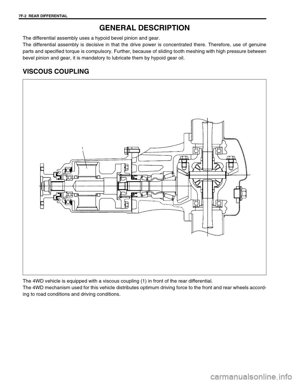
The differential assembly uses a hypoid bevel pinion and gear.
The differential assembly is decisive in that the drive power is concentrated there. Therefore, use of genuine
parts and specified torque is compulsory. Further, because of sliding tooth meshing with high pressure between
bevel pinion and gear, it is mandatory to lubricate them by hypoid gear oil.
VISCOUS COUPLING
The 4WD vehicle is equipped with a viscous coupling (1) in front of the rear differential.
The 4WD mechanism used for this vehicle distributes optimum driving force to the front and rear wheels accord-
ing to road conditions and driving conditions.
Page 225 of 447

REAR DIFFERENTIAL 7F-3
DIAGNOSIS
Condition Possible Cause Correction
Gear noise
Deteriorated or water mixed lubricant Repair and replenish.
Inadequate or insufficient lubricant Repair and replenish.
Maladjusted backlash between bevel pinion
and gearAdjust and prescribed.
Improper tooth contact in the mesh between
bevel pinion and gearAdjust or replace.
Loose bevel gear securing bolts Replace or retighten.
Damaged side gear(s) or side pinion(s) Replace.
Bearing noise
(Constant noise) Deteriorated or water mixed
lubricantRepair or replenish.
(Constant noise) Inadequate or insufficient
lubricantRepair or replenish.
(Noise while coasting) Damaged bearing(s) of
bevel pinionReplace.
(Noise while turning) Damaged differential side
bearing(s)Replace.
Oil leakage
Clogged breather plug Clean.
Worn or damaged oil seal Replace.
Excessive oil Adjust oil level.
Page 226 of 447

7F-4 REAR DIFFERENTIAL
ON-VEHICLE SERVICE
OIL CHANGE
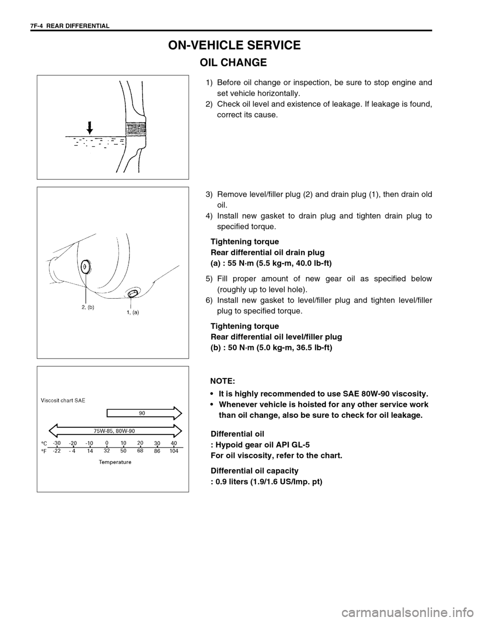
1) Before oil change or inspection, be sure to stop engine and
set vehicle horizontally.
2) Check oil level and existence of leakage. If leakage is found,
correct its cause.
3) Remove level/filler plug (2) and drain plug (1), then drain old
oil.
4) Install new gasket to drain plug and tighten drain plug to
specified torque.
Tightening torque
Rear differential oil drain plug
(a) : 55 N·m (5.5 kg-m, 40.0 lb-ft)
5) Fill proper amount of new gear oil as specified below
(roughly up to level hole).
6) Install new gasket to level/filler plug and tighten level/filler
plug to specified torque.
Tightening torque
Rear differential oil level/filler plug
(b) : 50 N·m (5.0 kg-m, 36.5 lb-ft)
Differential oil
: Hypoid gear oil API GL-5
For oil viscosity, refer to the chart.
Differential oil capacity
: 0.9 liters (1.9/1.6 US/Imp. pt)
NOTE:
It is highly recommended to use SAE 80W-90 viscosity.
Whenever vehicle is hoisted for any other service work
than oil change, also be sure to check for oil leakage.
Page 227 of 447

REAR DIFFERENTIAL 7F-5
UNIT REPAIR OVERHAUL
22 80 Nm (8.2 kg-m) 1513
17 16
15 12
14 7
22
22 2121
2020
1918 18
16 3 10 70-250 Nm (7.0-25.0 kg-m)
23 Nm (2.3kg-m)
23 Nm (2.3kg-m)
8
5
10
2611
23 Nm (2.3kg-m)
9
4
1 130 Nm(13.0 kg-m)
3
1. Companion flange nut
: After tightening nut to specified torque,
caulk nut securely.10. Drive bevel pinion nut
: After tightening nut to specified torque,
caulk nut securely.19. Differential pinion shaft
2. Companion flange 11. Viscous coupling 20. Differential pinion
3. Oil seal
: Apply grease 99000-25010 to oil seal
lip.12. Drive bevel gear (hypoid gear) 21. Differential pinion washer
4. Coupling case 13. Drive bevel pinion gear (hypoid gear) 22. Bevel gear bolt
: Apply thread lock cement 99000-
32110 to thread part of bolt.
5. Differential input hub 14. Differential case Do not reuse.
6. Bearing 15. Differential side bearing Tightening torque
7. Spacer 16. Pinion shaft bearing Apply differential oil
8. Differential carrier 17. Bevel pinion shim
9. Rear differential input flange 18. Differential gear