shaft SUZUKI SWIFT 2000 1.G Transmission Service Owner's Manual
[x] Cancel search | Manufacturer: SUZUKI, Model Year: 2000, Model line: SWIFT, Model: SUZUKI SWIFT 2000 1.GPages: 447, PDF Size: 10.54 MB
Page 28 of 447
7A-28 MANUAL TRANSMISSION
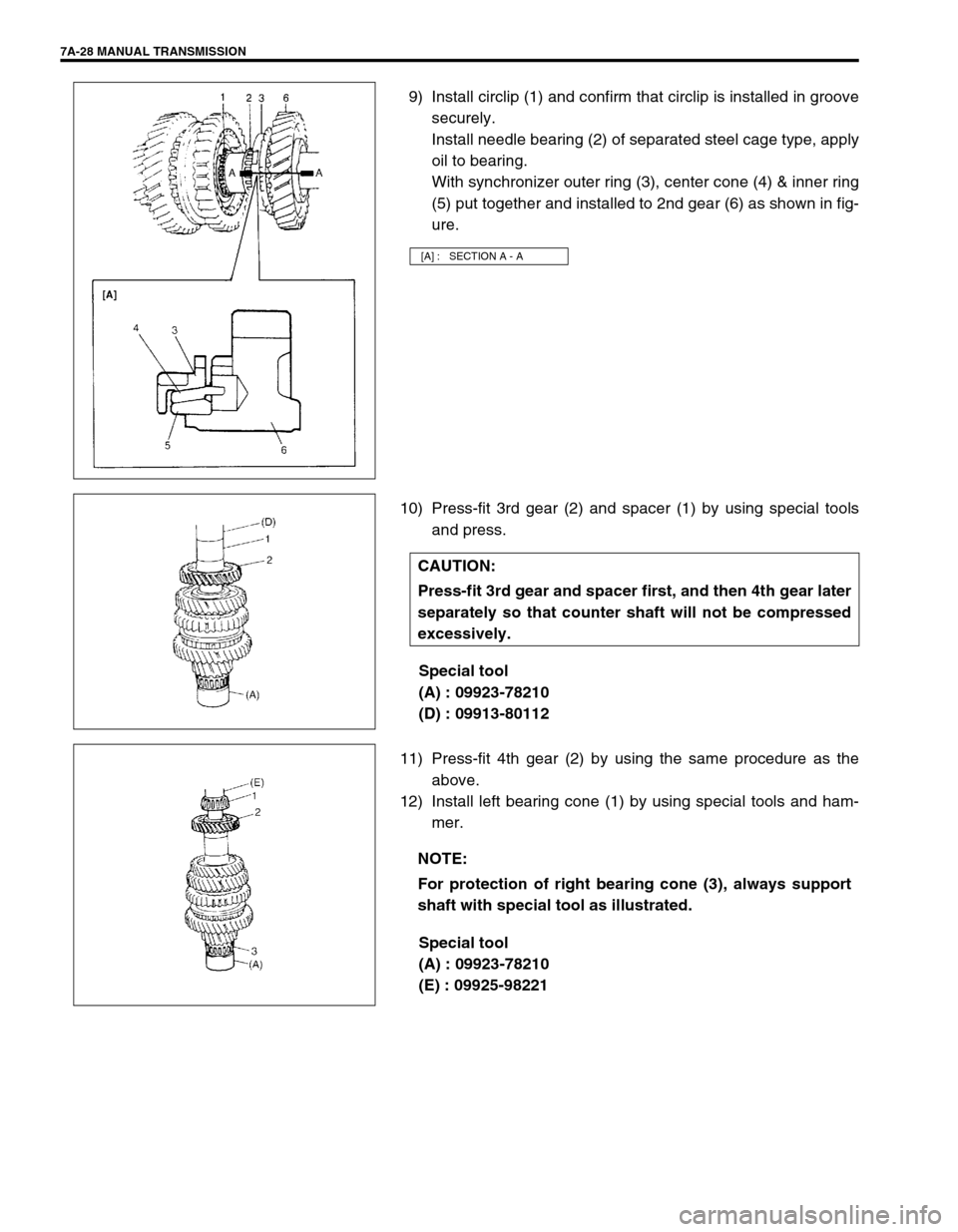
9) Install circlip (1) and confirm that circlip is installed in groove
securely.
Install needle bearing (2) of separated steel cage type, apply
oil to bearing.
With synchronizer outer ring (3), center cone (4) & inner ring
(5) put together and installed to 2nd gear (6) as shown in fig-
ure.
10) Press-fit 3rd gear (2) and spacer (1) by using special tools
and press.
Special tool
(A) : 09923-78210
(D) : 09913-80112
11) Press-fit 4th gear (2) by using the same procedure as the
above.
12) Install left bearing cone (1) by using special tools and ham-
mer.
Special tool
(A) : 09923-78210
(E) : 09925-98221
[A] : SECTION A - A
CAUTION:
Press-fit 3rd gear and spacer first, and then 4th gear later
separately so that counter shaft will not be compressed
excessively.
NOTE:
For protection of right bearing cone (3), always support
shaft with special tool as illustrated.
Page 29 of 447

MANUAL TRANSMISSION 7A-29
GEAR SHIFTER
Gear Shift and Select Shaft Assembly
1) Push spring pins out using specified spring pin removers as
shown bellow.
Special tool
(A) : 09922-85811 (4.5 mm)
(B) : 09925-78210 (6.0 mm)
(C) : 2.8 – 3.0 mm (0.11 – 0.12 in.) Commercially available
spring pin remover
2) Inspect component parts for wear, distortion or damage. If
any detect is found, replace detective part with new one.
High Speed and Low Speed Gear Shift Shafts Inspection
1) Using feeler gauge, check clearance between fork (1) and
sleeve (2) and replace those parts if it exceeds limit below.
Clearance between fork and sleeve
Service limit “a” : 1.0 mm (0.039 in.) NOTE:
When driving in spring pins, prevent shaft from being
bent by supporting it with wood block.
Assemble 5th & reverse gear shift cam with its pit and
spring pin aligned.
Make sure to select an appropriate spring by identify-
ing the painted colors to keep gear shifting perfor-
mance as designed.
– Low speed select spring - No paint
– Reverse select spring - Pink
1. E-ring 10. Spring pin
2. Washer 11. Ball
3. Reverse select spring 12. Gear shift & select shaft
4. Blank 13. 5th & reverse gear shift cam
5. Gear shift interlock plate 14. Spring pin
6. Ball 15. Cam guide return spring
7. Gear shift interlock spring 16. 5th & reverse gear shift cam guide
8. Gear shift & select lever 17. Spring pin
9. Spring pin 18. Low speed select spring
NOTE:
For correct judgement of parts replacement, carefully
inspect contact portion of fork and sleeve.
Page 30 of 447
7A-30 MANUAL TRANSMISSION
2) Insert each gear shift shaft into case and check that it moves
smoothly. If it doesn’t, correct by using oilstone, reamer or
the like.
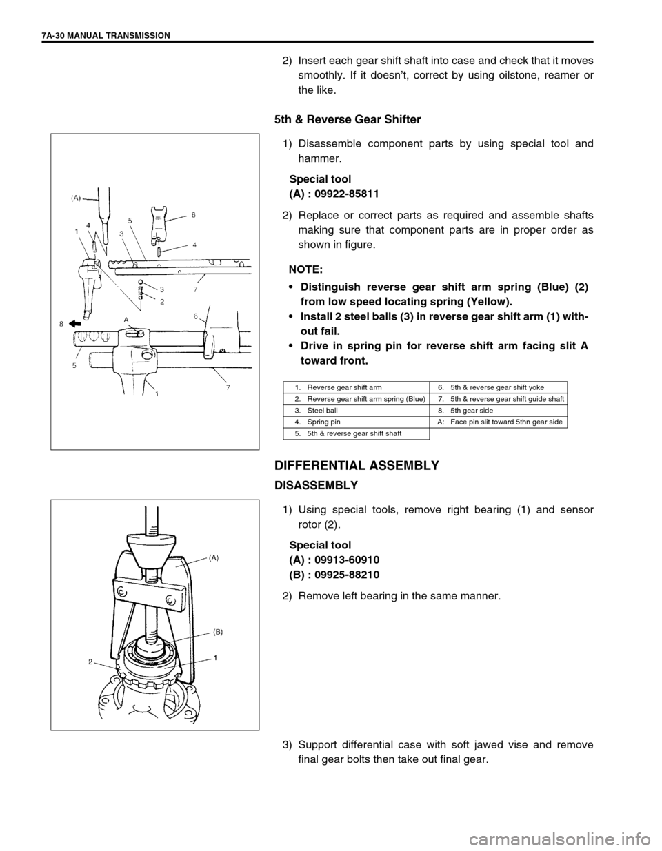
5th & Reverse Gear Shifter
1) Disassemble component parts by using special tool and
hammer.
Special tool
(A) : 09922-85811
2) Replace or correct parts as required and assemble shafts
making sure that component parts are in proper order as
shown in figure.
DIFFERENTIAL ASSEMBLY
DISASSEMBLY
1) Using special tools, remove right bearing (1) and sensor
rotor (2).
Special tool
(A) : 09913-60910
(B) : 09925-88210
2) Remove left bearing in the same manner.
3) Support differential case with soft jawed vise and remove
final gear bolts then take out final gear. NOTE:
Distinguish reverse gear shift arm spring (Blue) (2)
from low speed locating spring (Yellow).
Install 2 steel balls (3) in reverse gear shift arm (1) with-
out fail.
Drive in spring pin for reverse shift arm facing slit A
toward front.
1. Reverse gear shift arm 6. 5th & reverse gear shift yoke
2. Reverse gear shift arm spring (Blue) 7. 5th & reverse gear shift guide shaft
3. Steel ball 8. 5th gear side
4. Spring pin A: Face pin slit toward 5thn gear side
5. 5th & reverse gear shift shaft
Page 31 of 447

MANUAL TRANSMISSION 7A-31
4) Using special tool and hammer, drive out differential pinion
shaft pin and then disassemble component parts.
Special tool
(C) : 09922-85811
ADJUSTMENT AND REASSEMBLY
Judging from abnormality noted before disassembly and what is
found through visual check of component parts after disassembly,
prepare replacing parts and proceed to reassembly. Make sure
that all parts are clean.
1) Assemble differential gear and measure thrust play of differ-
ential gear as follows.
Differential gear thrust play
: 0.03 – 0.31 mm (0.001 – 0.012 in.)
Left side
Hold differential assembly with soft jawed vise and apply
measuring tip of dial gauge to top surface of gear.
Using 2 screwdrivers (1), move gear (2) up and down and
read movement of dial gauge pointer.
Special tool
(A) : 09900-20606
(B) : 09900-20701
Right side
Using similar procedure to the above, set dial gauge tip to
gear (1) shoulder.
Move gear up and down by hand and read dial gauge.
Special tool
(A) : 09900-20606
(B) : 09900-20701
2) If thrust play is out of specification, select suitable thrust
washer from among the following available size, install it and
check again that specified gear play is obtained.
Available thrust washer thickness
0.9, 0.95, 1.0, 1.05, 1.1, 1.15 and 1.2 mm
(0.035, 0.037, 0.039, 0.041, 0.043, 0.045, and 0.047 in.)
1. Differential case
2. Differential gear
3. Differential pinion shaft
Page 32 of 447
7A-32 MANUAL TRANSMISSION
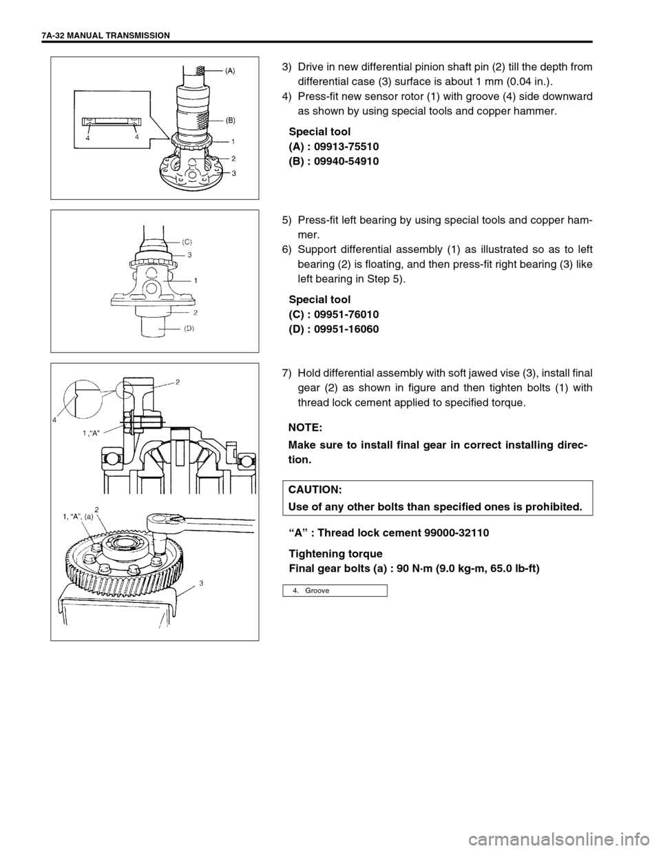
3) Drive in new differential pinion shaft pin (2) till the depth from
differential case (3) surface is about 1 mm (0.04 in.).
4) Press-fit new sensor rotor (1) with groove (4) side downward
as shown by using special tools and copper hammer.
Special tool
(A) : 09913-75510
(B) : 09940-54910
5) Press-fit left bearing by using special tools and copper ham-
mer.
6) Support differential assembly (1) as illustrated so as to left
bearing (2) is floating, and then press-fit right bearing (3) like
left bearing in Step 5).
Special tool
(C) : 09951-76010
(D) : 09951-16060
7) Hold differential assembly with soft jawed vise (3), install final
gear (2) as shown in figure and then tighten bolts (1) with
thread lock cement applied to specified torque.
“A” : Thread lock cement 99000-32110
Tightening torque
Final gear bolts (a) : 90 N·m (9.0 kg-m, 65.0 lb-ft)
NOTE:
Make sure to install final gear in correct installing direc-
tion.
CAUTION:
Use of any other bolts than specified ones is prohibited.
4. Groove
Page 33 of 447

MANUAL TRANSMISSION 7A-33
UNIT ASSEMBLY
DIFFERENTIAL TO LEFT CASE
ASSEMBLY
1) Install differential assembly (1) into right case (2).
2) Insert VSS (3) with grease applied to its O-ring, then tighten
it with bolt.
Grease 99000-25010
3) Join input shaft (5), countershaft (4), low speed gear shift
shaft (2) and high speed gear shift shaft (3) assemblies all
together, then install them into right case (1).
4) Install 5th & reverse gear shift shaft (1) with 5th & reverse
gear shift guide shaft (2) into right case (5). Reverse gear
shift arm (4) has to be joined with reverse gear shift lever (3)
at the same time.
5) Place reverse gear shift lever, fasten it with bolts after apply-
ing thread lock cement.
“A” : Thread lock cement 99000-32110
Tightening torque
Revers gear shift lever bolts
(a) : 23 N·m (2.3 kg-m, 17.0 lb-ft)
Distance between lever end and shaft bore
“a” : 5 mm (0.2 in.)
CAUTION:
Take care not to damage oil seal lip by input shaft, or oil
leakage may take place.
NOTE:
Input shaft right bearing on shaft can be installed into
right case by tapping shaft with plastic hammer.
Check to make sure that counter shaft is engaged with
final gear while installing.
NOTE:
When installing reverse gear shift lever, set it as the
following specification.
Page 34 of 447
7A-34 MANUAL TRANSMISSION
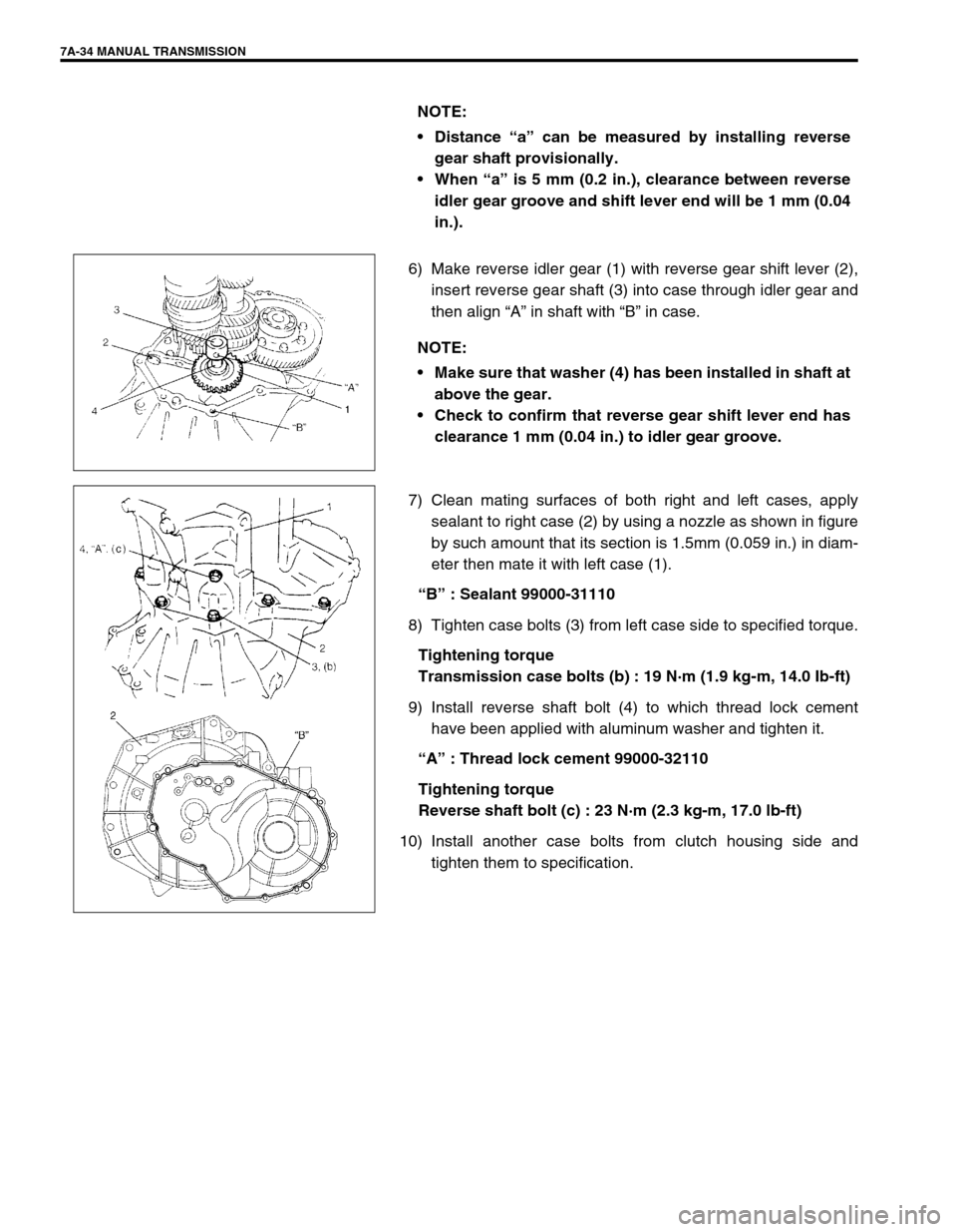
6) Make reverse idler gear (1) with reverse gear shift lever (2),
insert reverse gear shaft (3) into case through idler gear and
then align “A” in shaft with “B” in case.
7) Clean mating surfaces of both right and left cases, apply
sealant to right case (2) by using a nozzle as shown in figure
by such amount that its section is 1.5mm (0.059 in.) in diam-
eter then mate it with left case (1).
“B” : Sealant 99000-31110
8) Tighten case bolts (3) from left case side to specified torque.
Tightening torque
Transmission case bolts (b) : 19 N·m (1.9 kg-m, 14.0 Ib-ft)
9) Install reverse shaft bolt (4) to which thread lock cement
have been applied with aluminum washer and tighten it.
“A” : Thread lock cement 99000-32110
Tightening torque
Reverse shaft bolt (c) : 23 N·m (2.3 kg-m, 17.0 lb-ft)
10) Install another case bolts from clutch housing side and
tighten them to specification. NOTE:
Distance “a” can be measured by installing reverse
gear shaft provisionally.
When “a” is 5 mm (0.2 in.), clearance between reverse
idler gear groove and shift lever end will be 1 mm (0.04
in.).
NOTE:
Make sure that washer (4) has been installed in shaft at
above the gear.
Check to confirm that reverse gear shift lever end has
clearance 1 mm (0.04 in.) to idler gear groove.
Page 35 of 447
MANUAL TRANSMISSION 7A-35
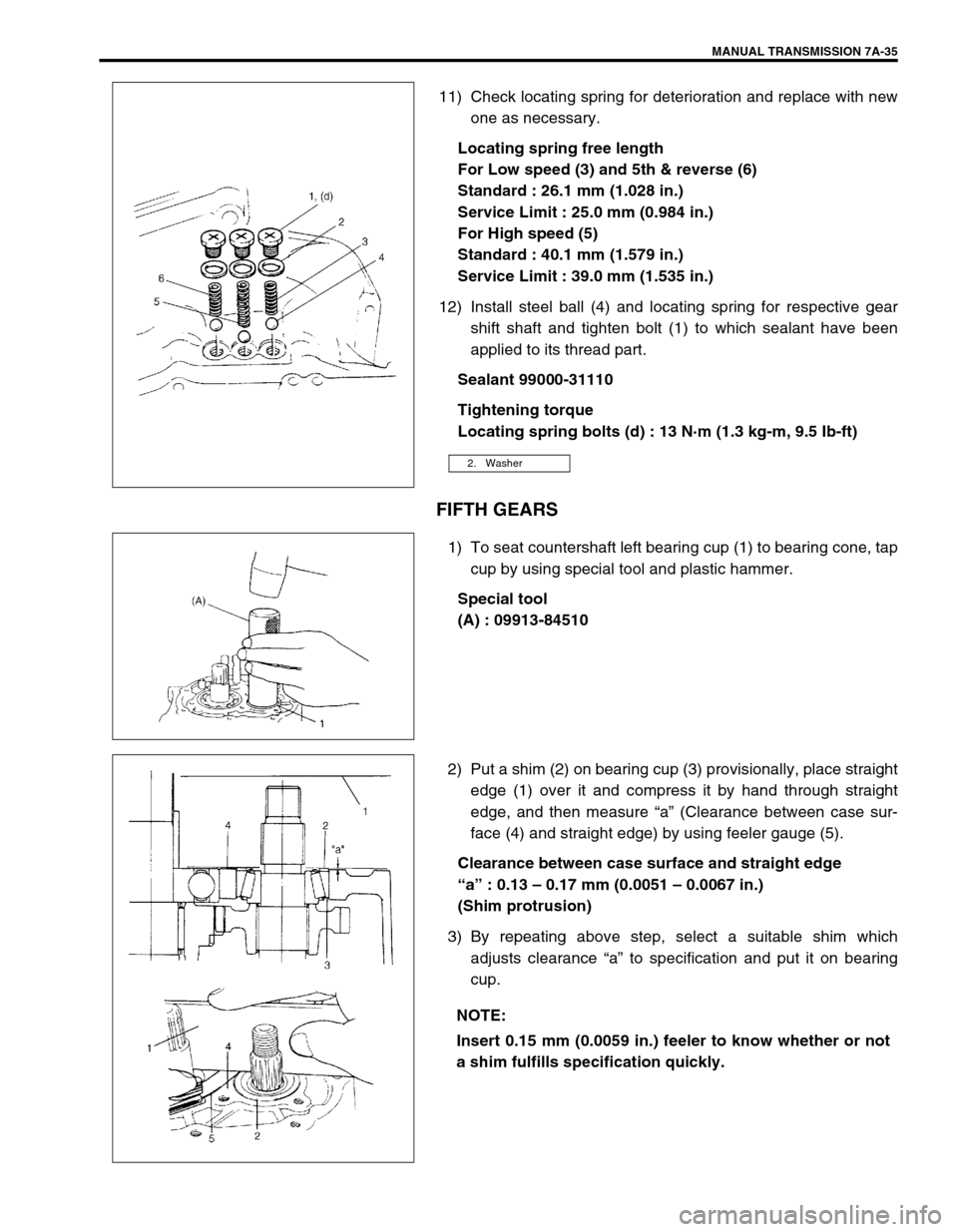
11) Check locating spring for deterioration and replace with new
one as necessary.
Locating spring free length
For Low speed (3) and 5th & reverse (6)
Standard : 26.1 mm (1.028 in.)
Service Limit : 25.0 mm (0.984 in.)
For High speed (5)
Standard : 40.1 mm (1.579 in.)
Service Limit : 39.0 mm (1.535 in.)
12) Install steel ball (4) and locating spring for respective gear
shift shaft and tighten bolt (1) to which sealant have been
applied to its thread part.
Sealant 99000-31110
Tightening torque
Locating spring bolts (d) : 13 N·m (1.3 kg-m, 9.5 Ib-ft)
FIFTH GEARS
1) To seat countershaft left bearing cup (1) to bearing cone, tap
cup by using special tool and plastic hammer.
Special tool
(A) : 09913-84510
2) Put a shim (2) on bearing cup (3) provisionally, place straight
edge (1) over it and compress it by hand through straight
edge, and then measure “a” (Clearance between case sur-
face (4) and straight edge) by using feeler gauge (5).
Clearance between case surface and straight edge
“a” : 0.13 – 0.17 mm (0.0051 – 0.0067 in.)
(Shim protrusion)
3) By repeating above step, select a suitable shim which
adjusts clearance “a” to specification and put it on bearing
cup.
2. Washer
NOTE:
Insert 0.15 mm (0.0059 in.) feeler to know whether or not
a shim fulfills specification quickly.
Page 36 of 447

7A-36 MANUAL TRANSMISSION
Available shim thickness
0.40, 0.45, 0.50, 0.55, 0.6, 0.65,0.7, 0.75, 0.8, 0.85, 0.9, 0.95,
1.0,1.05, 1.1 and 1.15 mm (0.015, 0.017, 0.019, 0.021,
0.023,0.025, 0.027, 0.029, 0.031, 0.033,0.035, 0.037, 0.039,
0.041, 0.043 and 0.045 in.)
4) Place left case plate (2) inserting its end in groove of shift
guide shaft (4) and tighten new adhesive pre-coated
screw(s) (1) (and new adhesive per-coated bolts (7) tempo-
rarily with less than specified toque.
5) Tighten new screw(s) (and new bolts) to specified torque
finally in the order of circled numbers (➀→➁→➂→➃→➄→➅
) shown in figure.
Tightening torque
Left case plate screw(s) (and bolts)
(a) : 11 N·m (1.1 kg-m, 8.0 lb-ft)
6) Assemble 5th speed synchronizer sleeve (4) and hub (3)
with keys (2) and springs (1).
Synchronizer key installation position
: A = B
7) Install 5th gear (1) to counter shaft facing machined boss A
inward. CAUTION:
Do not reuse left case plate screw(s) (1) (and bolts (7)).
Be sure to use new adhesive pre-coated screw(s) (and
new adhesive pre-coated bolts). Otherwise, screw(s)
(and/or bolts) may loosen.
NOTE:
After tightening screw(s) (and bolts), make sure that
countershaft (5) can be rotated by hand feeling certain
load.
[A]: In case 6 screws are used 3. Input shaft
[B]: In case 1 screw and 5 bolts are used 6. Transaxle left case
NOTE:
Short side C in keys, long flange D in hub and chamfered
spline F in sleeve should face inward (5th gear side).
[A] : Short side C D : Long flange (Inward)
[B] : Long side E : Key way
C : Short side (Inward) F : Chamfered spline (Inward)
A : Machined boss (Inside)
B : No machining (Outside)
Page 37 of 447
MANUAL TRANSMISSION 7A-37
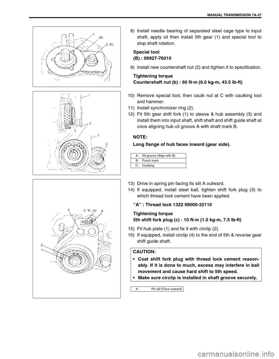
8) Install needle bearing of separated steel cage type to input
shaft, apply oil then install 5th gear (1) and special tool to
stop shaft rotation.
Special tool
(B) : 09927-76010
9) Install new countershaft nut (2) and tighten it to specification.
Tightening torque
Countershaft nut (b) : 60 N·m (6.0 kg-m, 43.5 lb-ft)
10) Remove special tool, then caulk nut at C with caulking tool
and hammer.
11) Install synchronizer ring (2).
12) Fit 5th gear shift fork (1) to sleeve & hub assembly (3) and
install them into input shaft, shift shaft and shift guide shaft at
once aligning hub oil groove A with shaft mark B.
13) Drive in spring pin facing its slit A outward.
14) If equipped, install steel ball, tighten shift fork plug (3) to
which thread lock cement have been applied.
“A” : Thread lock 1322 99000-32110
Tightening torque
5th shift fork plug (c) : 10 N·m (1.0 kg-m, 7.5 lb-ft)
15) Fit hub plate (1) and fix it with circlip (2).
16) If equipped, install circlip (4) to the end of 5th & reverse gear
shift guide shaft.
NOTE:
Long flange of hub faces inward (gear side).
A : Oil groove (Align with B)
B : Punch mark
C : Caulking
CAUTION:
Coat shift fork plug with thread lock cement reason-
ably. If it is done to much, excess may interfere in ball
movement and cause hard shift to 5th speed.
Make sure circlip is installed in shaft groove securely.
A : Pin slit (Face outward)