shaft SUZUKI SWIFT 2000 1.G Transmission Service Repair Manual
[x] Cancel search | Manufacturer: SUZUKI, Model Year: 2000, Model line: SWIFT, Model: SUZUKI SWIFT 2000 1.GPages: 447, PDF Size: 10.54 MB
Page 81 of 447

AUTOMATIC TRANSMISSION (4 A/T) 7B-39
Figure for Step 1, 2
Figure for Step 2, 33 1) Turn ignition switch OFF and disconnect
output shaft speed sensor – input shaft
speed sensor coupler. (See figure.)
2) Measure resistance between terminal “3”
(of disconnected sensor side coupler) and
body ground then terminal “4” (of discon-
nected sensor side coupler) and body
ground.
Is it about 0 Ω
?
(See figure.)Replace output shaft
speed sensor.Go to Step 4.
4 1) Turn ignition switch OFF and connect out-
put shaft speed sensor coupler then discon-
nect TCM couplers.
2) Measure resistance between terminal “C43-
6” (of disconnected harness side coupler)
and body ground then terminal “C43-14” (of
disconnected harness side coupler) and
body ground.
Is it about 0 Ω
?
(See figure.)“WHT” or “BLK” wire
shorted to ground.Go to Step 5.
5 Measure resistance between terminal “C43-6”
and “C43-13” (of disconnected harness side
coupler) then terminal “C43-14” and “C43-13”
(of disconnected harness side coupler).
Is it about 0 Ω
?
(See figure.)“WHT” wire or “BLK” wire
shorted to shield portion.Poor connection of termi-
nal “C43-6” or “C43-14” of
the TCM.
If all the above are in
good condition, substitute
a known-good TCM and
recheck. Step Action Yes No
1. Output shaft speed sensor
2. Input shaft speed sensor coupler
1. Terminal “3”
2. Terminal “4”
Page 95 of 447
AUTOMATIC TRANSMISSION (4 A/T) 7B-53
INSPECTION OF TCM AND ITS CIRCUITS
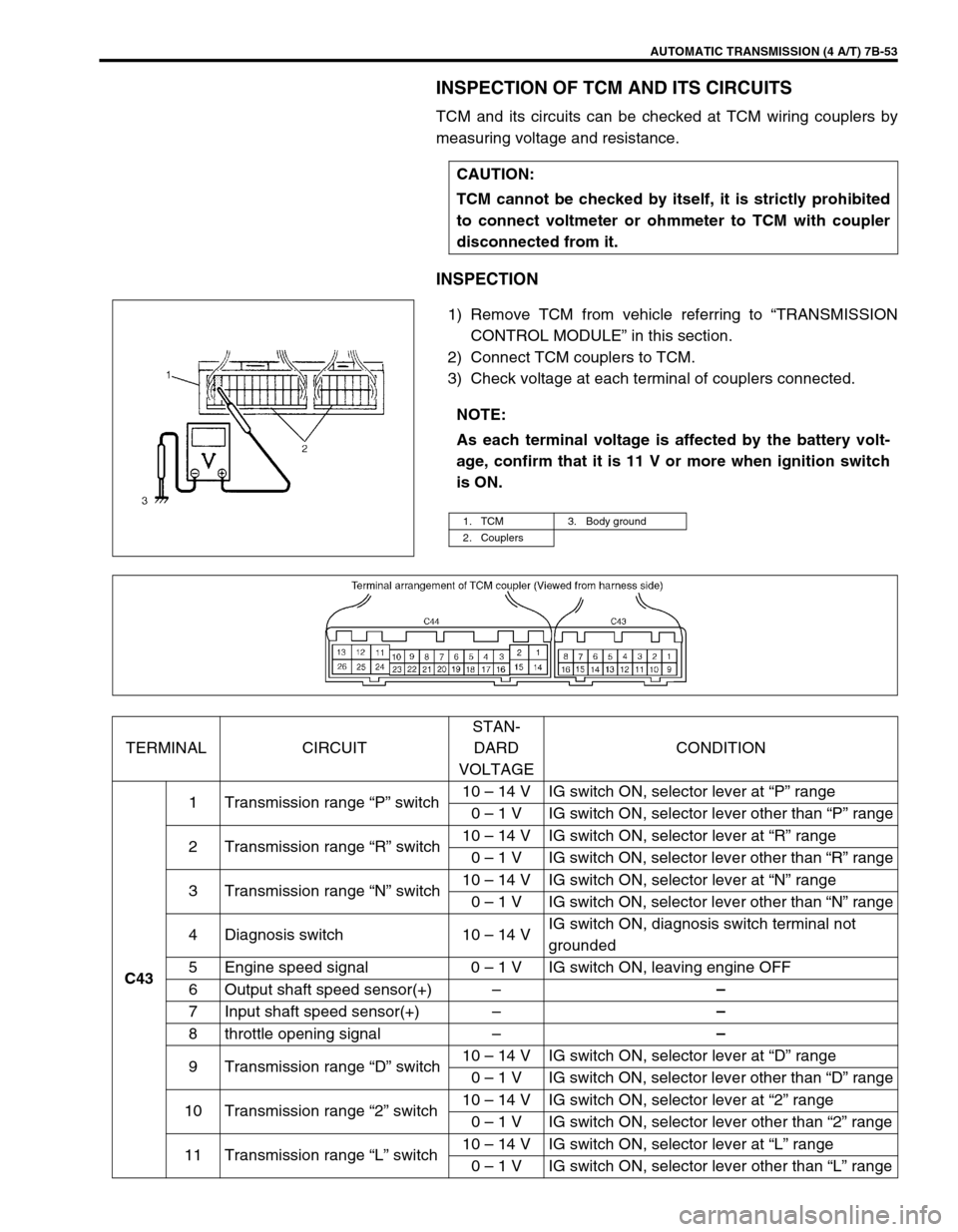
TCM and its circuits can be checked at TCM wiring couplers by
measuring voltage and resistance.
INSPECTION
1) Remove TCM from vehicle referring to “TRANSMISSION
CONTROL MODULE” in this section.
2) Connect TCM couplers to TCM.
3) Check voltage at each terminal of couplers connected.CAUTION:
TCM cannot be checked by itself, it is strictly prohibited
to connect voltmeter or ohmmeter to TCM with coupler
disconnected from it.
NOTE:
As each terminal voltage is affected by the battery volt-
age, confirm that it is 11 V or more when ignition switch
is ON.
1. TCM 3. Body ground
2. Couplers
TERMINAL CIRCUITSTAN-
DARD
VOLTAGECONDITION
C431 Transmission range “P” switch10 – 14 V IG switch ON, selector lever at “P” range
0 – 1 V IG switch ON, selector lever other than “P” range
2 Transmission range “R” switch10 – 14 V IG switch ON, selector lever at “R” range
0 – 1 V IG switch ON, selector lever other than “R” range
3 Transmission range “N” switch10 – 14 V IG switch ON, selector lever at “N” range
0 – 1 V IG switch ON, selector lever other than “N” range
4 Diagnosis switch 10 – 14 VIG switch ON, diagnosis switch terminal not
grounded
5 Engine speed signal 0 – 1 V IG switch ON, leaving engine OFF
6 Output shaft speed sensor(+)––
7 Input shaft speed sensor(+)––
8 throttle opening signal––
9 Transmission range “D” switch10 – 14 V IG switch ON, selector lever at “D” range
0 – 1 V IG switch ON, selector lever other than “D” range
10 Transmission range “2” switch10 – 14 V IG switch ON, selector lever at “2” range
0 – 1 V IG switch ON, selector lever other than “2” range
11 Transmission range “L” switch10 – 14 V IG switch ON, selector lever at “L” range
0 – 1 V IG switch ON, selector lever other than “L” range
Page 96 of 447
7B-54 AUTOMATIC TRANSMISSION (4 A/T)
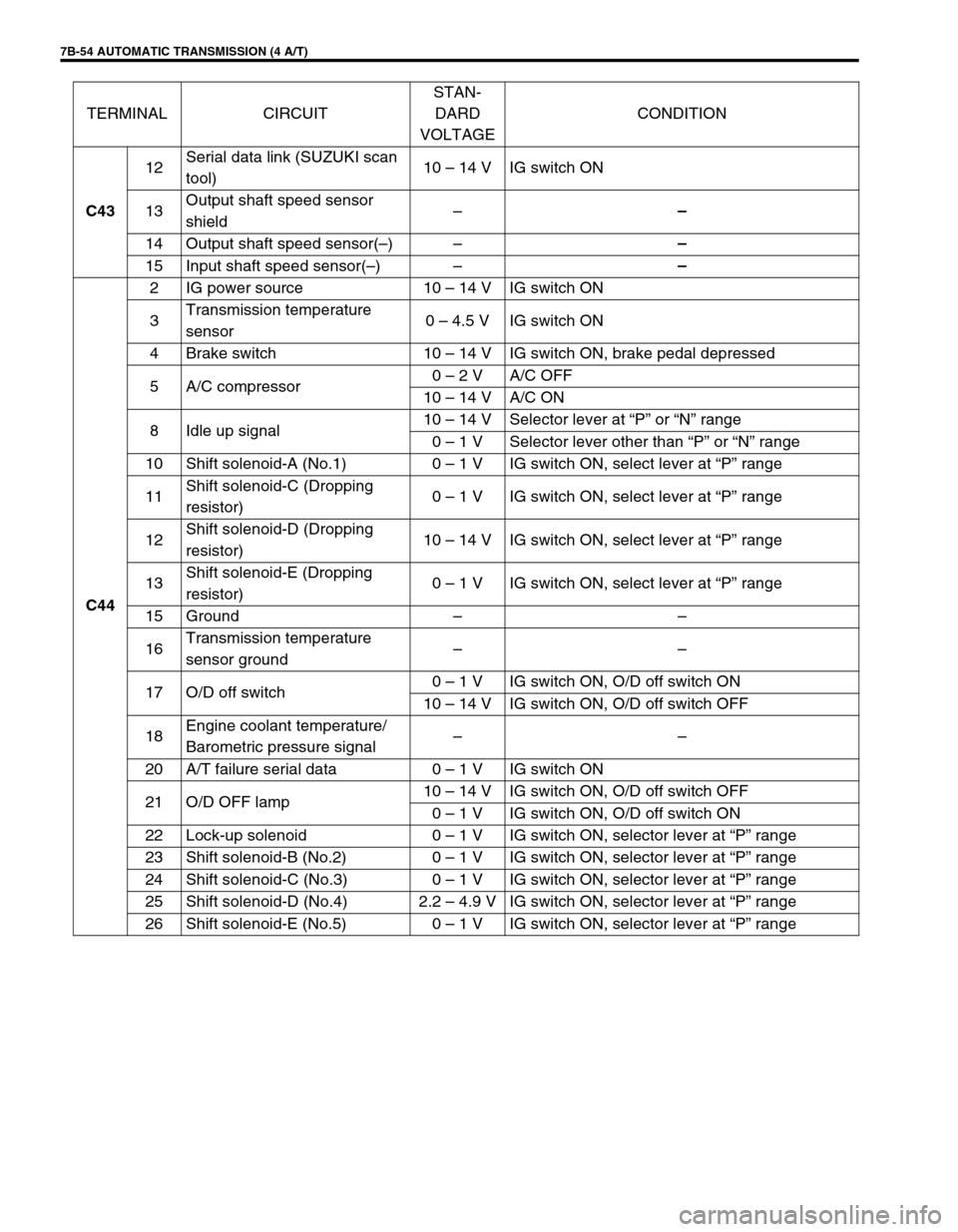
C4312Serial data link (SUZUKI scan
tool)10 – 14 V IG switch ON
13Output shaft speed sensor
shield––
14 Output shaft speed sensor(–)––
15 Input shaft speed sensor(–)––
C442 IG power source 10 – 14 V IG switch ON
3Transmission temperature
sensor0 – 4.5 V IG switch ON
4 Brake switch 10 – 14 V IG switch ON, brake pedal depressed
5 A/C compressor0 – 2 V A/C OFF
10 – 14 V A/C ON
8 Idle up signal10 – 14 V Selector lever at “P” or “N” range
0 – 1 V Selector lever other than “P” or “N” range
10 Shift solenoid-A (No.1) 0 – 1 V IG switch ON, select lever at “P” range
11Shift solenoid-C (Dropping
resistor)0 – 1 V IG switch ON, select lever at “P” range
12Shift solenoid-D (Dropping
resistor)10 – 14 V IG switch ON, select lever at “P” range
13Shift solenoid-E (Dropping
resistor)0 – 1 V IG switch ON, select lever at “P” range
15 Ground––
16Transmission temperature
sensor ground––
17 O/D off switch0 – 1 V IG switch ON, O/D off switch ON
10 – 14 V IG switch ON, O/D off switch OFF
18Engine coolant temperature/
Barometric pressure signal––
20 A/T failure serial data 0 – 1 V IG switch ON
21 O/D OFF lamp10 – 14 V IG switch ON, O/D off switch OFF
0 – 1 V IG switch ON, O/D off switch ON
22 Lock-up solenoid 0 – 1 V IG switch ON, selector lever at “P” range
23 Shift solenoid-B (No.2) 0 – 1 V IG switch ON, selector lever at “P” range
24 Shift solenoid-C (No.3) 0 – 1 V IG switch ON, selector lever at “P” range
25 Shift solenoid-D (No.4) 2.2 – 4.9 V IG switch ON, selector lever at “P” range
26 Shift solenoid-E (No.5) 0 – 1 V IG switch ON, selector lever at “P” range TERMINAL CIRCUITSTAN-
DARD
VOLTAGECONDITION
Page 104 of 447

7B-62 AUTOMATIC TRANSMISSION (4 A/T)
OUTPUT SHAFT SPEED SENSOR (A/T VSS)
INSPECTION
1) Disconnect negative cable at battery.
2) Disconnect output shaft speed sensor – input shaft speed
sensor coupler (1).
3) Check resistance between output shaft speed sensor termi-
nals (2).
Output shaft speed sensor resistance
Standard : 160 – 200
Ω
ΩΩ Ω at 20°C (68°F)
REMOVAL
1) Disconnect negative cable at battery.
2) Disconnect output shaft speed sensor – input shaft speed
sensor coupler.
3) Remove output shaft speed sensor (1) by removing its bolt.
INSTALLATION
1) Apply A/T fluid to output shaft speed sensor o-ring.
2) Install output shaft speed sensor (1) to A/T case and tighten
bolt to specified torque.
Tightening torque
Output shaft speed sensor bolt
(a) : 8 N·m (0.8 kg-m, 6.0 lb-ft)
3) Connect output shaft speed sensor – input shaft speed sen-
sor coupler.
4) Connect negative cable to battery.
Page 105 of 447

AUTOMATIC TRANSMISSION (4 A/T) 7B-63
INPUT SHAFT SPEED SENSOR
INSPECTION
1) Disconnect negative cable at battery.
2) Disconnect output shaft speed sensor – input shaft speed
sensor coupler (1).
3) Check resistance between input shaft speed sensor termi-
nals (2).
Input shaft speed sensor resistance
Standard : 160 – 200
Ω
ΩΩ Ω at 20°C (68°F)
REMOVAL
1) Disconnect negative cable at battery.
2) Disconnect output shaft speed sensor – input shaft speed
sensor coupler.
3) Remove input shaft speed sensor (1) by removing its bolt.
INSTALLATION
1) Apply A/T fluid to input shaft speed sensor O-ring.
2) Install input shaft speed sensor (1) to A/T case and tighten
bolt to specified torque.
Tightening torque
Input shaft speed sensor bolt
(b) : 8 N·m (0.8 kg-m, 6.0 lb-ft)
3) Connect output shaft speed sensor – input shaft speed sen-
sor coupler.
4) Connect negative cable to battery.
VEHICLE SPEED SENSOR (VSS)
Refer to Section 6E for removal, installation and inspection.
THROTTLE POSITION SENSOR
INSPECTION
Check throttle position sensor referring to Section 6E.
Page 110 of 447

7B-68 AUTOMATIC TRANSMISSION (4 A/T)
DIFFERENTIAL SIDE OIL SEAL
REPLACEMENT
1) Lift up vehicle and drain transmission oil.
2) Remove drive shaft joints from differential gear of transmis-
sion.
Refer to Section 4 for procedure to disconnect drive shaft
joints.
For differential side oil seal removal, it is not necessary to
remove drive shafts from steering knuckle.
For 4WD vehicle, remove transfer referring to Section 7D.
3) Remove differential side oil seal (1) by using flat end rod or
like.
4) Install new differential side oil seal by using special tool.
Special tool
(A) : 09940-53111
(B) : 09913-75510
5) Install drive shaft referring to Section 4.
6) Refill A/T fluid referring to “FLUID CHANGE” in this section. NOTE:
For oil seal installation, press-fit oil seal so that transmis-
sion case end face is flush with oil seal end face.
2. Steering gear box
3. A/T oil pan
4. Torque converter hous-
ing
5. Transmission case
Page 117 of 447
AUTOMATIC TRANSMISSION (4 A/T) 7B-75
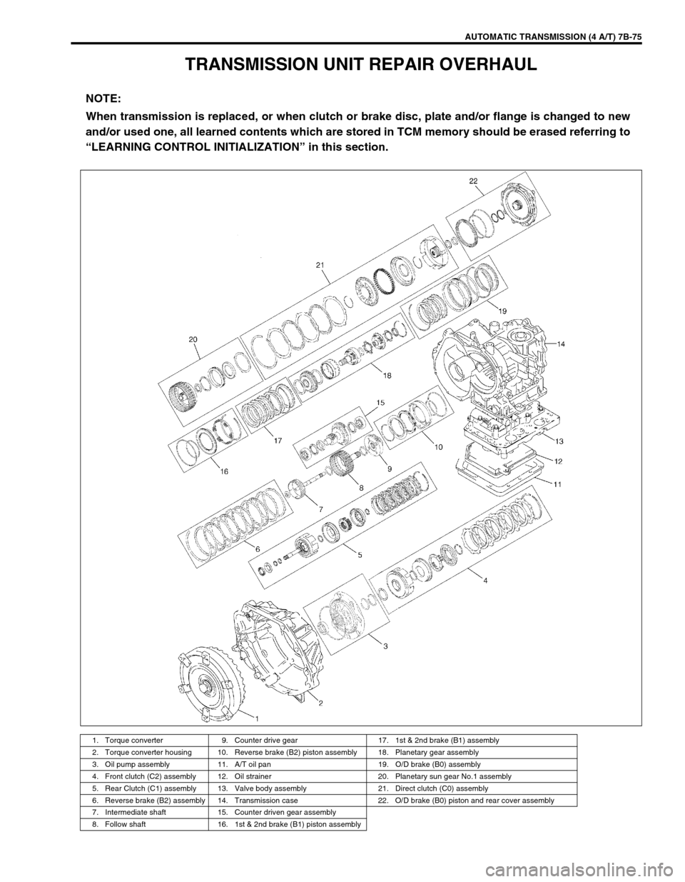
TRANSMISSION UNIT REPAIR OVERHAUL
NOTE:
When transmission is replaced, or when clutch or brake disc, plate and/or flange is changed to new
and/or used one, all learned contents which are stored in TCM memory should be erased referring to
“LEARNING CONTROL INITIALIZATION” in this section.
1. Torque converter 9. Counter drive gear 17. 1st & 2nd brake (B1) assembly
2. Torque converter housing 10. Reverse brake (B2) piston assembly 18. Planetary gear assembly
3. Oil pump assembly 11. A/T oil pan 19. O/D brake (B0) assembly
4. Front clutch (C2) assembly 12. Oil strainer 20. Planetary sun gear No.1 assembly
5. Rear Clutch (C1) assembly 13. Valve body assembly 21. Direct clutch (C0) assembly
6. Reverse brake (B2) assembly 14. Transmission case 22. O/D brake (B0) piston and rear cover assembly
7. Intermediate shaft 15. Counter driven gear assembly
8. Follow shaft 16. 1st & 2nd brake (B1) piston assembly
Page 118 of 447

7B-76 AUTOMATIC TRANSMISSION (4 A/T)
DISMOUNTING
1) Take down transmission with engine. For its procedure, refer
to Section 6A1.
2) For 4WD vehicle, remove transfer referring to Section 7D
For 2WD vehicle, remove engine rear mounting No.1
bracket and engine rear mounting No.2 bracket with stiff-
ener.
3) Remove torque converter housing lower plate (1).
4) Remove drive plate bolts.
To lock drive plate (1), engage a flat head rod or the like (2)
with drive plate gear.
5) Remove starting motor.
6) Remove bolts and nut fastening engine and transmission,
then detach transmission from engine.
NOTE:
When detaching transmission from engine, move it in
parallel with crankshaft and use care so as not to apply
excessive force to drive plate and torque converter.
WARNING:
Be sure to keep transmission with torque converter hori-
zontal or facing up throughout the work. Should it be
tilted with torque converter down, converter may fall off
and cause personal injury.
Page 121 of 447
AUTOMATIC TRANSMISSION (4 A/T) 7B-79
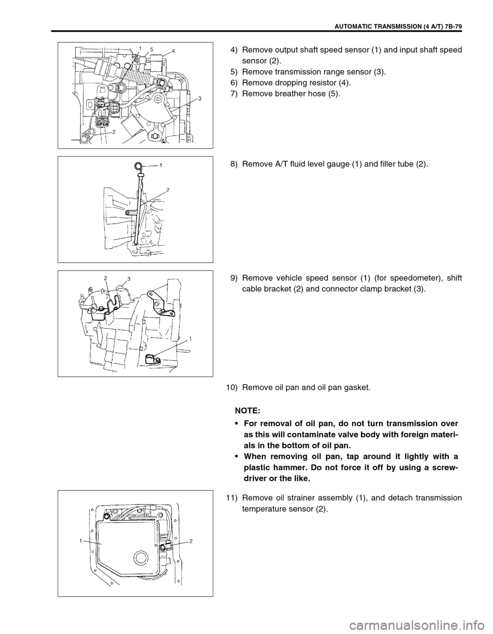
4) Remove output shaft speed sensor (1) and input shaft speed
sensor (2).
5) Remove transmission range sensor (3).
6) Remove dropping resistor (4).
7) Remove breather hose (5).
8) Remove A/T fluid level gauge (1) and filler tube (2).
9) Remove vehicle speed sensor (1) (for speedometer), shift
cable bracket (2) and connector clamp bracket (3).
10) Remove oil pan and oil pan gasket.
11) Remove oil strainer assembly (1), and detach transmission
temperature sensor (2).
NOTE:
For removal of oil pan, do not turn transmission over
as this will contaminate valve body with foreign materi-
als in the bottom of oil pan.
When removing oil pan, tap around it lightly with a
plastic hammer. Do not force it off by using a screw-
driver or the like.
Page 124 of 447
7B-82 AUTOMATIC TRANSMISSION (4 A/T)
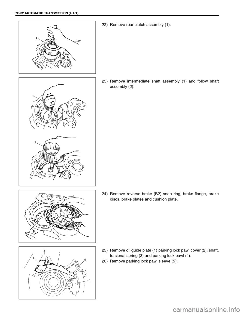
22) Remove rear clutch assembly (1).
23) Remove intermediate shaft assembly (1) and follow shaft
assembly (2).
24) Remove reverse brake (B2) snap ring, brake flange, brake
discs, brake plates and cushion plate.
25) Remove oil guide plate (1) parking lock pawl cover (2), shaft,
torsional spring (3) and parking lock pawl (4).
26) Remove parking lock pawl sleeve (5).