Electri SUZUKI SWIFT 2000 1.G Transmission Service Workshop Manual
[x] Cancel search | Manufacturer: SUZUKI, Model Year: 2000, Model line: SWIFT, Model: SUZUKI SWIFT 2000 1.GPages: 447, PDF Size: 10.54 MB
Page 43 of 447
AUTOMATIC TRANSMISSION (4 A/T) 7B-1
6F1
6F2
6G
6H
6K
7A
7A1
7C1
7D
7B
7F
8A
8B
8C
8D
8E
9
10
10A
10B
SECTION 7B
AUTOMATIC TRANSMISSION (4 A/T)
CONTENTS
GENERAL DESCRIPTION ...............................7B-3
ELECTRONIC SHIFT CONTROL SYSTEM . 7B-6
TRANSMISSION CONTROL MODULE
(TCM) ........................................................ 7B-7
FAIL SAFE FUNCTION ............................. 7B-8
CHANGE MECHANISM .......................... 7B-10
AUTOMATIC GEAR SHIFT DIAGRAM ... 7B-11
DIAGNOSIS ....................................................7B-13
AUTOMATIC TRANSMISSION
DIAGNOSTIC FLOW TABLE ...................... 7B-13
TROUBLE DIAGNOSIS TABLE .................. 7B-18
STALL TEST ........................................... 7B-20
TIME LAG TEST ..................................... 7B-21
LINE PRESSURE TEST ......................... 7B-22
ENGINE BRAKE TEST ........................... 7B-23
“P” RANGE TEST.................................... 7B-23
ELECTRONIC CONTROL SYSTEM
DIAGNOSIS ................................................ 7B-24
PRECAUTIONS IN DIAGNOSING
TROUBLES ............................................. 7B-24
DTC CHECK ........................................... 7B-25
DTC CLEARANCE .................................. 7B-27
DTC TABLE............................................. 7B-28
TCM POWER AND GROUND CIRCUIT
CHECK .................................................... 7B-30
DTC P0715 (DTC NO.14) INPUT/
TURBINE SPEED SENSOR CIRCUIT
MALFUNCTION ...................................... 7B-31
DTC P0730 (DTC NO. 18) INCORRECT
GEAR RATIO .......................................... 7B-33
DTC P0753 (DTC NO.21/22) SHIFT
SOLENOID-A (NO.1) ELECTRICAL ....... 7B-35DTC P0758 (DTC NO.23/24) SHIFT
SOLENOID-B (NO.2) ELECTRICAL ....... 7B-35
DTC P0743 (DTC NO.25/26) TCC
(LOCK-UP CLUTCH) SYSTEM
ELECTRICAL .......................................... 7B-35
DTC P0741 (DTC NO.29) TCC
(LOCK-UP) SOLENOID
PERFORMANCE OR STUCK OFF ........ 7B-37
DTC P0720 (DTC NO. 31) OUTPUT
SHAFT SPEED SENSOR CIRCUIT
MALFUNCTION ...................................... 7B-38
DTC P1700 (DTC NO.32/33)
THROTTLE POSITION SIGNAL INPUT
MALFUNCTION ...................................... 7B-41
DTC P0705 (DTC NO.34)
TRANSMISSION RANGE SENSOR
(SWITCH) CIRCUIT MALFUNCTION ..... 7B-43
DTC P0725 (DTC NO.35) ENGINE
SPEED INPUT CIRCUIT
MALFUNCTION ...................................... 7B-45
DTC P0710 (DTC No.36/38)
TRANSMISSION TEMPERATURE
SENSOR CIRCUIT MALFUNCTION ...... 7B-47
DTC P0763 (DTC NO.43) SHIFT
SOLENOID-C (NO.3) ELECTRICAL ....... 7B-49
DTC P0768 (DTC NO.45) SHIFT
SOLENOID-B (NO.4) ELECTRICAL ....... 7B-49
DTC P0773 (DTC NO.48) SHIFT
SOLENOID-E (NO.5) ELECTRICAL ....... 7B-49
DTC P1709 (DTC NO.51) ENGINE
COOLANT TEMPERATURE/BAROMETRIC
PRESSURE SIGNAL CIRCUIT............... 7B-51 WARNING:
For vehicles equipped with Supplemental Restraint (Air Bag) System :
Service on and around the air bag system components or wiring must be performed only by an
authorized SUZUKI dealer. Refer to “Air Bag System Components and Wiring Location View” under
“General Description” in air bag system section in order to confirm whether you are performing ser-
vice on or near the air bag system components or wiring. Please observe all WARNINGS and “Ser-
vice Precautions” under “On-Vehicle Service” in air bag system section before performing service
on or around the air bag system components or wiring. Failure to follow WARNINGS could result in
unintentional activation of the system or could render the system inoperative. Either of these two
conditions may result in severe injury.
Technical service work must be started at least 90 seconds after the ignition switch is turned to the
“LOCK” position and the negative cable is disconnected from the battery. Otherwise, the system
may be activated by reserve energy in the Sensing and Diagnostic Module (SDM).
Page 44 of 447
7B-2 AUTOMATIC TRANSMISSION (4 A/T)
DTC P0702/P1702 (DTC No.52)
TRANSMISSION CONTROL SYSTEM
ELECTRICAL OR INTERNAL
MALFUNCTION OF TCM ....................... 7B-52
INSPECTION OF TCM AND ITS
CIRCUITS ............................................... 7B-53
ON-VEHICLE SERVICE ................................. 7B-55
MAINTENANCE SERVICE ......................... 7B-55
FLUID LEVEL AT NORMAL OPERATING
TEMPERATURE ..................................... 7B-55
FLUID LEVEL AT ROOM
TEMPERATURE ..................................... 7B-56
FLUID CHANGE ..................................... 7B-56
SELECTOR LEVER .................................... 7B-57
TRANSMISSION RANGE SENSOR
(SHIFT SWITCH) ........................................ 7B-58
SELECTOR CABLE .................................... 7B-60
OUTPUT SHAFT SPEED SENSOR
(A/T VSS) .................................................... 7B-62
INPUT SHAFT SPEED SENSOR ............... 7B-63
VEHICLE SPEED SENSOR (VSS)............. 7B-63
THROTTLE POSITION SENSOR............... 7B-63
ENGINE COOLANT TEMP. (ECT)
SENSOR ..................................................... 7B-64
DROPPING RESISTOR ............................. 7B-64
O/D OFF SWITCH ...................................... 7B-65
SHIFT SOLENOID VALVES AND
TRANSMISSION TEMPERATURE
SENSOR ..................................................... 7B-65
SHIFT SOLENOID VALVES ................... 7B-66
TRANSMISSION TEMPERATURE
SENSOR ................................................. 7B-66
DIFFERENTIAL SIDE OIL SEAL ................ 7B-68TRANSMISSION CONTROL MODULE
(TCM).......................................................... 7B-69
LEARNING CONTROL INITIALIZATION 7B-70
BRAKE INTERLOCK SYSTEM
(IF EQUIPPED)........................................... 7B-70
KEY INTERLOCK CABLE
(IF EQUIPPED)........................................... 7B-72
TRANSMISSION UNIT REPAIR
OVERHAUL ................................................... 7B-75
DISMOUNTING .......................................... 7B-76
REMOUNTING ........................................... 7B-77
UNIT DISASSEMBLY ................................. 7B-78
DISASSEMBLY/ASSEMBLY OF
SUBASSEMBLY ......................................... 7B-88
OIL PUMP ............................................... 7B-88
FRONT CLUTCH (C2 CLUTCH) ............ 7B-91
REAR CLUTCH (C1 CLUTCH) ............... 7B-95
DIRECT CLUTCH (C0 CLUTCH) ......... 7B-100
PLANETARY SET................................. 7B-104
VALVE BODY ....................................... 7B-106
DIFFERENTIAL ASSEMBLY ................ 7B-112
REAR COVER (O/D BRAKE PISTON
ASSEMBLY) ......................................... 7B-115
PLANETARY SUN GEAR NO.1
ASSEMBLY .......................................... 7B-115
TORQUE CONVERTER HOUSING ..... 7B-116
TRANSMISSION CASE ........................ 7B-117
UNIT ASSEMBLY ..................................... 7B-118
TIGHTENING TORQUE SPECIFICATION .. 7B-136
SPECIAL TOOL ........................................... 7B-137
REQUIRED SERVICE MATERIAL .............. 7B-139
Page 52 of 447
7B-10 AUTOMATIC TRANSMISSION (4 A/T)
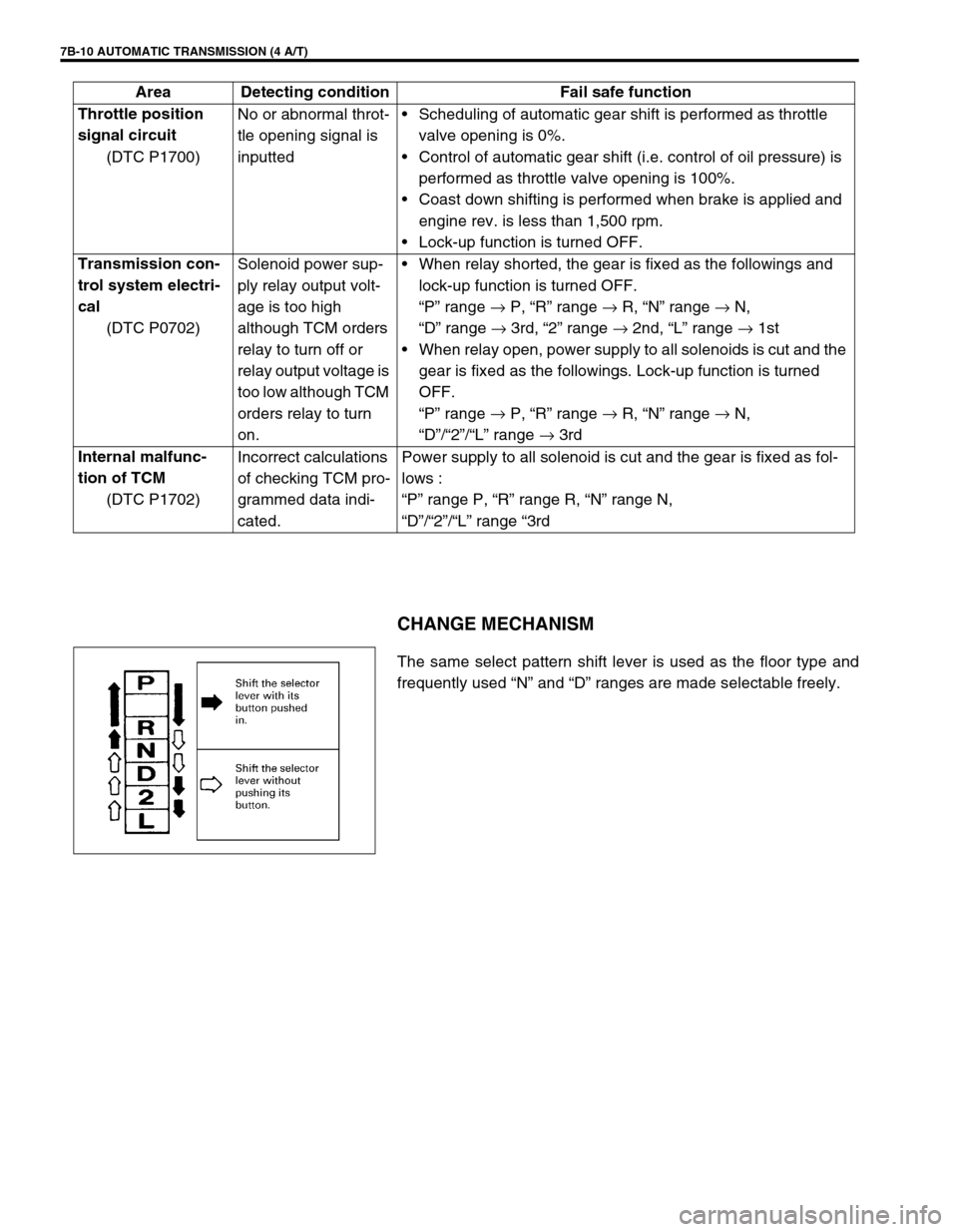
CHANGE MECHANISM
The same select pattern shift lever is used as the floor type and
frequently used “N” and “D” ranges are made selectable freely. Throttle position
signal circuit
(DTC P1700)No or abnormal throt-
tle opening signal is
inputtedScheduling of automatic gear shift is performed as throttle
valve opening is 0%.
Control of automatic gear shift (i.e. control of oil pressure) is
performed as throttle valve opening is 100%.
Coast down shifting is performed when brake is applied and
engine rev. is less than 1,500 rpm.
Lock-up function is turned OFF.
Transmission con-
trol system electri-
cal
(DTC P0702)Solenoid power sup-
ply relay output volt-
age is too high
although TCM orders
relay to turn off or
relay output voltage is
too low although TCM
orders relay to turn
on.When relay shorted, the gear is fixed as the followings and
lock-up function is turned OFF.
“P” range →
P, “R” range →
R, “N” range →
N,
“D” range →
3rd, “2” range →
2nd, “L” range →
1st
When relay open, power supply to all solenoids is cut and the
gear is fixed as the followings. Lock-up function is turned
OFF.
“P” range →
P, “R” range →
R, “N” range →
N,
“D”/“2”/“L” range →
3rd
Internal malfunc-
tion of TCM
(DTC P1702)Incorrect calculations
of checking TCM pro-
grammed data indi-
cated.Power supply to all solenoid is cut and the gear is fixed as fol-
lows :
“P” range P, “R” range R, “N” range N,
“D”/“2”/“L” range “3rd Area Detecting condition Fail safe function
Page 58 of 447
7B-16 AUTOMATIC TRANSMISSION (4 A/T)
2. DIAGNOSTIC TROUBLE CODE (DTC) CHECK, RECORD AND CLEARANCE
To check DTC, refer to “DTC CHECK” in this section. When a DTC exists, it means existence of a malfunction in
the system represented by that code but whether it still exists (current) or it occurred in the past and has gone
(history) is unknown. To know it, clear this DTC once (Refer to “DTC CLEARANCE” in this section.), perform
test drive and/or “TROUBLE SYMPTOM CONFIRMATION” in this section and then check DTC again as
described in “DTC CHECK”. Attempt to diagnose the trouble based on the DTC recorded in this step only or fail-
ure to clear the DTC in this step may mislead the diagnosis or make diagnosing difficult. Even after checking the
DTC with the SUZUKI scan tool, diagnosis should be performed according to this flow chart to check TCM for
proper self-diagnosis function.
3 and 4. VISUAL INSPECTION
As a preliminary step, perform visual check of the following items that support proper function of the automatic
transmission.
5.TROUBLE SYMPTOM CONFIRMATION
Check if what the customer claimed in “CUSTOMER COMPLAINT ANALYSIS” is actually found in the vehicle
and if that symptom is found, whether it is identified as a failure. (This step should be shared with the customer
if possible.)
When the symptom is not actually found, possibility is :
The symptom occurs under certain conditions.
----- Retry with the vehicle under different conditions.
The trouble occurred only temporarily and normal operation has been restored.
----- Perform “DTC CHECK” and if the diagnostic trouble code is indicated, inspect according to the flow
table for that DTC.
6 and 7. RECHECKING AND RECORD OF DTC
Refer to “DTC CHECK” in this section.INSPECTION ITEM REFERRING SECTION
Engine oil ----- level, leakage Section 0B
Engine coolant ----- level, leakage Section 0B
A/T fluid ----- level, leakage, color Section 0B
Battery ----- fluid level, corrosion of terminal
A/T fluid hoses ----- disconnection, looseness, deterioration
Connectors of electric wire harness ----- disconnection, friction Section 8
Fuses ----- burning Section 8
Parts ----- installation, bolt ----- looseness
Parts ----- deformation
Other parts that can be checked visually
Also add following items at engine start.
Indicator, warning lights in combination meter ----- ON
(indicating abnormality in system) or OFFSection 8C
Other parts that can be checked visually
Page 59 of 447
AUTOMATIC TRANSMISSION (4 A/T) 7B-17
8. AUTOMATIC TRANSMISSION BASIC CHECK AND TROUBLE DIAGNOSIS TABLE
Perform basic automatic transmission check according to the list below first. When the end of the list has been
reached, check the part of system suspected as a possible cause referring to “TROUBLE DIAGNOSIS TABLE”
and based on symptoms appearing on vehicle (symptoms obtained through steps of customer complaint analy-
sis, trouble symptom confirmation and/or A/T basic check) and repair or replace faulty parts, if any.
AUTOMATIC TRANSMISSION BASIC CHECK LIST
1) Power Supply Voltage Check
Check that the battery voltage is within 10 – 14 V at engine stop.
2) A/T Fluid Check
Check A/T fluid level and quality.
3) STALL TEST
Perform stall test. Refer to “STALL TEST” in this section for details.
4) LINE PRESSURE TEST
Perform line pressure test. Refer to “LINE PRESSURE TEST” in this section.
5) ROAD TEST
Perform road test to understand correctly the trouble area.
6) Electrical Harness and Coupler Check
Check the connection of the harness coupler. Check for the loose connection of the harness, loose connec-
tion of the terminals.
9. DIAGNOSTIC TROUBLE CODE FLOW TABLE
Based on the DTC indicated in STEP 6 and STEP 7 and referring to “DTC CHECK”, locate the cause of the
trouble, namely in a sensor, switch, wire harness, connector, actuator, TCM or other part and repair or replace
faulty parts.
10. CHECK FOR INTERMITTENT PROBLEM
Check parts where an intermittent trouble is easy to occur (e.g. wire harness, connector, etc.), referring to
“INTERMITTENT AND POOR CONNECTION” in Section 0A and related circuit of DTC recorded in Step 2.
11. FINAL CONFIRMATION TEST
Confirm that the problem symptom has gone and the automatic transmission is free from any abnormal condi-
tions. If what has been repaired is related to the malfunction DTC, clear the DTC once and perform test driving
and confirm that a normal code is indicated.
Page 60 of 447
7B-18 AUTOMATIC TRANSMISSION (4 A/T)
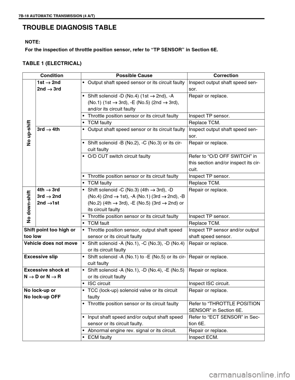
TROUBLE DIAGNOSIS TABLE
TABLE 1 (ELECTRICAL)
NOTE:
For the inspection of throttle position sensor, refer to “TP SENSOR” in Section 6E.
Condition Possible Cause Correction
No up-shift
1st
→
→→ → 2nd
2nd
→
→→ → 3rdOutput shaft speed sensor or its circuit faulty Inspect output shaft speed sen-
sor.
Shift solenoid -D (No.4) (1st →
→→ →
2nd), -A
(No.1) (1st →
→→ →
3rd), -E (No.5) (2nd →
→→ →
3rd),
and/or its circuit faultyRepair or replace.
Throttle position sensor or its circuit faulty Inspect TP sensor.
TCM faulty Replace TCM.
3rd
→
→→ → 4th
Output shaft speed sensor or its circuit faulty Inspect output shaft speed sen-
sor.
Shift solenoid -B (No.2), -C (No.3) or its cir-
cuit faultyRepair or replace.
O/D CUT switch circuit faulty Refer to “O/D OFF SWITCH” in
this section and/or inspect its cir-
cuit.
Throttle position sensor or its circuit faulty Inspect TP sensor.
TCM faulty Replace TCM.
No down-shift
4th
→
→→ → 3rd
3rd
→
→→ → 2nd
2nd
→
→→ →1stShift solenoid -C (No.3) (4th →
→→ →
3rd), -D
(No.4) (2nd →
→→ →
1st), -A (No.1) (3rd →
→→ →
2nd), -B
(No.2) (4th →
→→ →
3rd), -E (No.5) (3rd →
→→ →
2nd) or
its circuit faultyRepair or replace.
Throttle position sensor or its circuit faulty Inspect TP sensor.
TCM fault Replace TCM.
Shift point too high or
too lowThrottle position sensor, output shaft speed
sensor or its circuit faultyInspect TP sensor and/or output
shaft speed sensor.
Vehicle does not move
Shift solenoid -A (No.1), -C (No.3), -D (No.4)
or its circuit faultyRepair or replace.
Excessive slip
Shift solenoid -A (No.1) to -E (No.5) or its cir-
cuit faultyRepair or replace.
Excessive shock at
N
→
→→ → D or N
→
→→ → RShift solenoid -A (No.1), -D (No.4), -E (No.5)
or its circuit faultyRepair or replace.
ISC circuit Inspect ISC circuit.
No lock-up or
No lock-up OFFTCC (lock-up) solenoid valve or its circuit
faultyRepair or replace.
Throttle position sensor or its circuit faulty Refer to “THROTTLE POSITION
SENSOR” in Section 6E.
Input shaft speed and/or output shaft speed
sensor or its circuit faulty.Refer to “ECT SENSOR” in Sec-
tion 6E.
Abnormal engine rev. signal or its circuit. Repair or replace.
ECM faulty Inspect ECM.
Page 66 of 447
7B-24 AUTOMATIC TRANSMISSION (4 A/T)
ELECTRONIC CONTROL SYSTEM DIAGNO-
SIS
TCM has on-board diagnostic system (a system self-diagnosis
function). Investigate where the trouble is by referring to “DIAG-
NOSTIC FLOW TABLE” and “DTC TABLE” in this section.
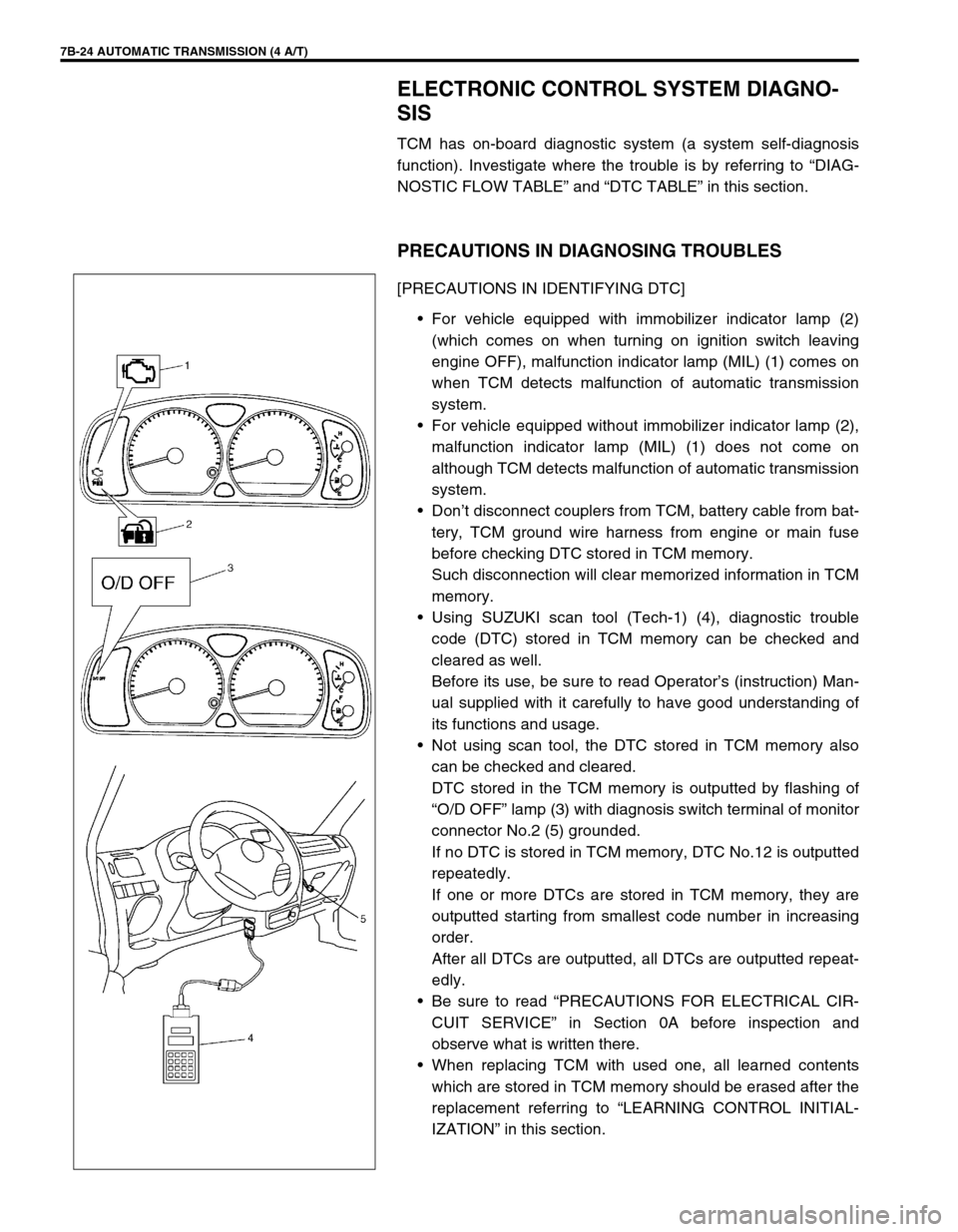
PRECAUTIONS IN DIAGNOSING TROUBLES
[PRECAUTIONS IN IDENTIFYING DTC]
For vehicle equipped with immobilizer indicator lamp (2)
(which comes on when turning on ignition switch leaving
engine OFF), malfunction indicator lamp (MIL) (1) comes on
when TCM detects malfunction of automatic transmission
system.
For vehicle equipped without immobilizer indicator lamp (2),
malfunction indicator lamp (MIL) (1) does not come on
although TCM detects malfunction of automatic transmission
system.
Don’t disconnect couplers from TCM, battery cable from bat-
tery, TCM ground wire harness from engine or main fuse
before checking DTC stored in TCM memory.
Such disconnection will clear memorized information in TCM
memory.
Using SUZUKI scan tool (Tech-1) (4), diagnostic trouble
code (DTC) stored in TCM memory can be checked and
cleared as well.
Before its use, be sure to read Operator’s (instruction) Man-
ual supplied with it carefully to have good understanding of
its functions and usage.
Not using scan tool, the DTC stored in TCM memory also
can be checked and cleared.
DTC stored in the TCM memory is outputted by flashing of
“O/D OFF” lamp (3) with diagnosis switch terminal of monitor
connector No.2 (5) grounded.
If no DTC is stored in TCM memory, DTC No.12 is outputted
repeatedly.
If one or more DTCs are stored in TCM memory, they are
outputted starting from smallest code number in increasing
order.
After all DTCs are outputted, all DTCs are outputted repeat-
edly.
Be sure to read “PRECAUTIONS FOR ELECTRICAL CIR-
CUIT SERVICE” in Section 0A before inspection and
observe what is written there.
When replacing TCM with used one, all learned contents
which are stored in TCM memory should be erased after the
replacement referring to “LEARNING CONTROL INITIAL-
IZATION” in this section.
Page 70 of 447

7B-28 AUTOMATIC TRANSMISSION (4 A/T)
DTC TABLE
DTC NO.
“O/D OFF” Lamp
Flashing Pattern of DTC
(Not using scan tool)DETECTING ITEMSMIL
Using
scan toolNot using
scan toolVehicle
equipped
with
immobi-
lizer indi-
cator lampVehicle
equipped
without
immobi-
lizer indi-
cator lamp
–12 Normal––
P0715 14Input/Turbine speed sensor circuit
malfunction1 driving
cycleNot
applicable
P0730 18 Incorrect gear ratio2 driving
cyclesNot
applicable
P075321
Shift solenoid-A (No.1) electrical1 driving
cycleNot
applicable
22
P075823
Shift solenoid-B (No.2) electrical1 driving
cycleNot
applicable
24
P0763 43 Shift solenoid-C (No.3) electrical1 driving
cycleNot
applicable
P0768 45 Shift solenoid-D (No.4) electrical1 driving
cycleNot
applicable
P0773 48 Shift solenoid-E (No.5) electrical1 driving
cycleNot
applicable
P074325
Torque converter clutch (lock-up)
system electrical1 driving
cycleNot
applicable
26
Page 77 of 447
AUTOMATIC TRANSMISSION (4 A/T) 7B-35
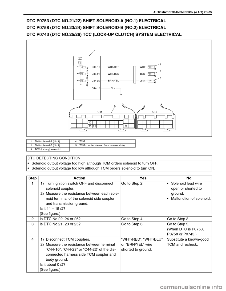
DTC P0753 (DTC NO.21/22) SHIFT SOLENOID-A (NO.1) ELECTRICAL
DTC P0758 (DTC NO.23/24) SHIFT SOLENOID-B (NO.2) ELECTRICAL
DTC P0743 (DTC NO.25/26) TCC (LOCK-UP CLUTCH) SYSTEM ELECTRICAL
1. Shift solenoid-A (No.1) 4. TCM
2. Shift solenoid-B (No.2) 5. TCM coupler (viewed from harness side)
3. TCC (lock-up) solenoid
DTC DETECTING CONDITION
Solenoid output voltage too high although TCM orders solenoid to turn OFF.
Solenoid output voltage too low although TCM orders solenoid to turn ON.
Step Action Yes No
1 1) Turn ignition switch OFF and disconnect
solenoid coupler.
2) Measure the resistance between each sole-
noid terminal of the solenoid side coupler
and transmission ground.
Is it 11 – 15 Ω
?
(See figure.)Go to Step 2.Solenoid lead wire
open or shorted to
ground.
Malfunction of solenoid.
2 Is DTC No.22, 24 or 26? Go to Step 4. Go to Step 3.
3 Is DTC No.21, 23 or 25? Go to Step 6. Go to Step 5.
(When DTC is P0753,
P0758 or P0743.)
4 1) Disconnect TCM couplers.
2) Measure the resistance between terminal
“C44-10”, “C44-23” or “C44-22” of the dis-
connected harness side TCM coupler and
body ground.
Is it about 0 Ω
?
(See figure.)“WHT/RED”, “WHT/BLU”
or “BRN/YEL” wire
shorted to ground.Substitute a known-good
TCM and recheck.
Page 91 of 447

AUTOMATIC TRANSMISSION (4 A/T) 7B-49
DTC P0763 (DTC NO.43) SHIFT SOLENOID-C (NO.3) ELECTRICAL
DTC P0768 (DTC NO.45) SHIFT SOLENOID-B (NO.4) ELECTRICAL
DTC P0773 (DTC NO.48) SHIFT SOLENOID-E (NO.5) ELECTRICAL
1. Dropping resistor 4. Shift solenoid-D (No.4) 7. TCM coupler (viewed from harness side)
2. solenoid coupler 5. Shift solenoid-E (No.5)
3. Shift solenoid-C (No.3) 6. TCM
12V
C44-24
C44-13
C44-12
C44-11
C44-25
C44-26
C44-15
1
6
23
4
5
BRN/WHTGRY/BLU
RED/BLU
BLU/ORN
BRN
BLK/YEL
BRN/WHT
BLK/YEL
BRN
BLK
RED
YEL
BRN
7
DTC DETECTING CONDITION
Solenoid output voltage too high or too low differently from TCM order.
Step Action Yes No
1 1) Turn ignition switch OFF and disconnect sole-
noid coupler.
2) Measure resistance between terminal of sole-
noid coupler and transmission ground. (See
figure.)
Is it 2.5 – 3.5 Ω
?Go to Step 2.Solenoid lead wire open or
shorted to ground.
Malfunction of solenoid
valve.
2 1) Disconnect TCM couplers.
2) Measure resistance between terminal of dis-
connected body side solenoid coupler and
terminal “C44-11”, “C44-12” or “C44-13” of
disconnected harness side TCM coupler.
(See chart.)
Is it 6.5 – 8.5 Ω
?Go to Step 3. Inspect dropping resister refer-
ring to “DROPPING RESIS-
TOR” in this section.
If OK, circuit between TCM
and dropping resister or drop-
ping resister and solenoid cou-
pler open.
3 Check continuity between terminal “C44-24”,
“C44-25” or “C44-26” of disconnected TCM cou-
pler and terminal of disconnected body side sole-
noid coupler. (See chart.)
Is there continuity?Go to Step 4. Circuit between TCM and sole-
noid coupler open.