ring SUZUKI SWIFT 2000 1.G Transmission Service Workshop Manual
[x] Cancel search | Manufacturer: SUZUKI, Model Year: 2000, Model line: SWIFT, Model: SUZUKI SWIFT 2000 1.GPages: 447, PDF Size: 10.54 MB
Page 1 of 447
MANUAL TRANSMISSION 7A-1
6F1
6F2
6G
6H
6K
7A1
7B1
7C1
7A
7E
7F
8A
8B
8C
8D
8E
9
10
10A
10B
SECTION 7A
MANUAL TRANSMISSION
CONTENTS
GENERAL DESCRIPTION .............................. 7A-2
CONSTRUCTION AND SERVICING ........... 7A-2
TRANSMISSION FOR 2WD MODEL....... 7A-3
TRANSMISSION FOR 4WD MODEL....... 7A-4
DIAGNOSIS ..................................................... 7A-5
ON-VEHICLE SERVICE .................................. 7A-5
OIL CHANGE ............................................... 7A-6
DIFFERENTIAL SIDE OIL SEAL ................. 7A-6
GEAR SHIFT CONTROL LEVER AND
CABLE ......................................................... 7A-8
VEHICLE SPEED SENSOR (VSS) ............ 7A-10
UNIT REPAIR OVERHAUL ........................... 7A-11
TRANSMISSION UNIT............................... 7A-11
TRASMISSION CASE ................................ 7A-12
INPUT & COUNTER SHAFT...................... 7A-13
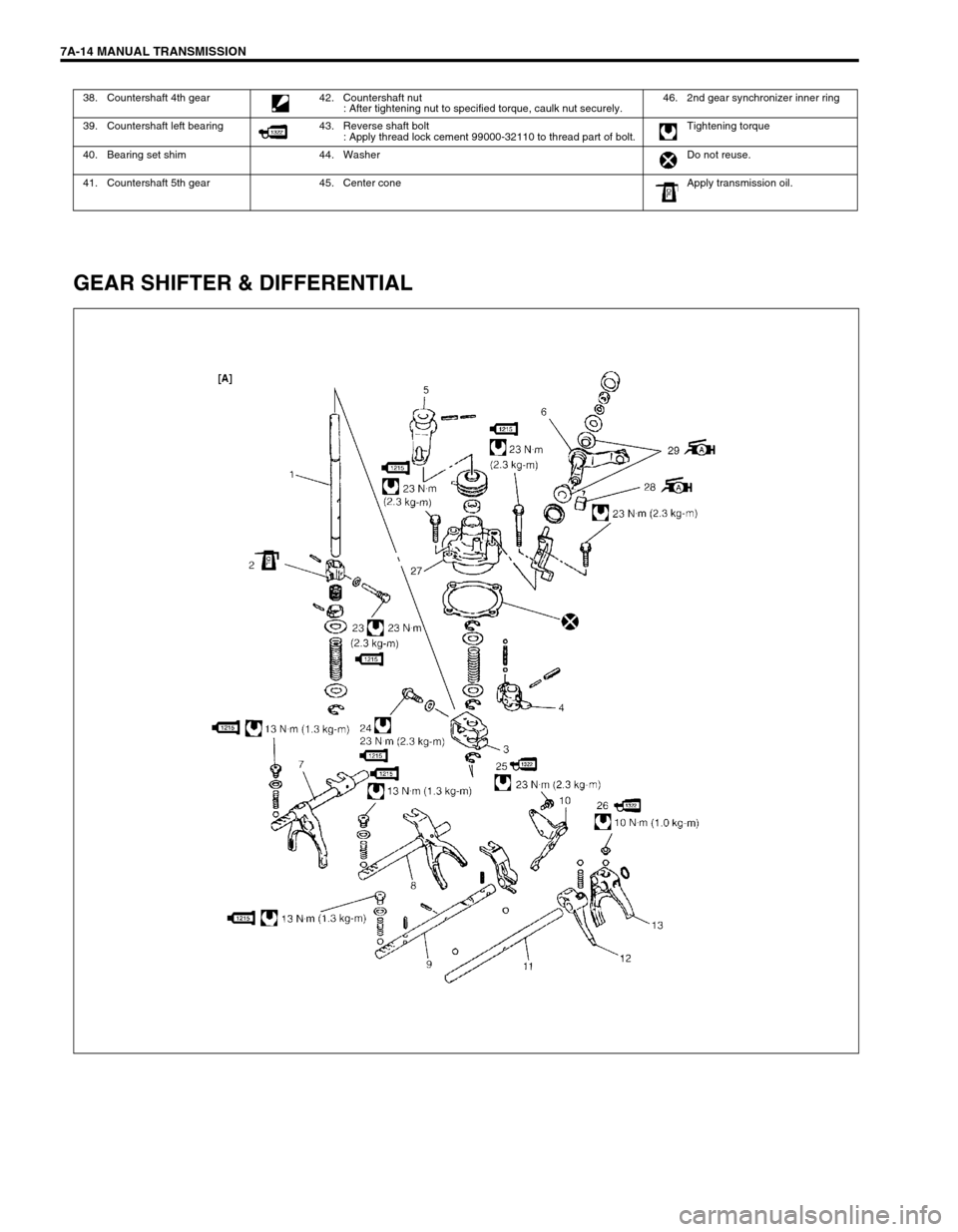
GEAR SHIFTER & DIFFERENTIAL ........... 7A-14
TRANSMISSION UNIT............................... 7A-16
UNIT DISASSEMBLY ................................ 7A-17
FIFTH GEARS........................................ 7A-17GEAR SHIFTER, INPUT SHAFT AND
COUNTER SHAFT................................. 7A-19
RIGHT CASE ......................................... 7A-20
SUB ASSEMBLY SERVICE ...................... 7A-21
RIGHT CASE ......................................... 7A-21
LEFT CASE............................................ 7A-21
INPUT SHAFT ASSEMBLY ................... 7A-22
COUNTER SHAFT ASSEMBLY ............ 7A-25
GEAR SHIFTER..................................... 7A-29
DIFFERENTIAL ASSEMBLY ................. 7A-30
UNIT ASSEMBLY ...................................... 7A-33
DIFFERENTIAL TO LEFT CASE ........... 7A-33
FIFTH GEARS ....................................... 7A-35
GEAR SHIFT AND SELECT SHAFT
ASSEMBLY ............................................ 7A-38
TIGHTENING TORQUE SPECIFICATION.... 7A-39
REQUIRED SERVICE MATERIAL................ 7A-40
SPECIAL TOOL ............................................ 7A-40
WARNING:
For vehicles equipped with Supplemental Restraint (Air Bag) System :
• Service on and around the air bag system components or wiring must be performed only by an
authorized SUZUKI dealer. Refer to “Air Bag System Components and Wiring Location View” under
“General Description” in air bag system section in order to confirm whether you are performing ser-
vice on or near the air bag system components or wiring. Please observe all WARNINGS and “Ser-
vice Precautions” under “On-Vehicle Service” in air bag system section before performing service
on or around the air bag system components or wiring. Failure to follow WARNINGS could result in
unintentional activation of the system or could render the system inoperative. Either of these two
conditions may result in severe injury.
Technical service work must be started at least 90 seconds after the ignition switch is turned to the
“LOCK” position and the negative cable is disconnected from the battery. Otherwise, the system
may be activated by reserve energy in the Sensing and Diagnostic Module (SDM).
Page 2 of 447
7A-2 MANUAL TRANSMISSION
GENERAL DESCRIPTION
CONSTRUCTION AND SERVICING
The transmission provides five forward speeds and one reverse speed by means of three synchronizers and
three shafts-input shaft, countershaft and reverse gear shaft. All forward gears are in constant mesh, and
reverse uses a sliding idler gear arrangement.
The low speed synchronizer is mounted on counter shaft and engaged with counter shaft first gear or second
gear, while the high speed synchronizer is done on input shaft and engaged with input shaft third gear or fourth
gear.
The fifth speed synchronizer on input shaft is engaged with input shaft fifth gear mounted on the input shaft.
The double cone synchronizing mechanism is provided to 2nd gear synchromesh device for high performance
of shifting to 2nd gear.
The countershaft turns the final gear and differential assembly, thereby turning the front drive shafts which are
attached to the front wheels.
4WD model is equipped with transfer assembly on transmission being mated to right side of differential output in
transmission.
For servicing, it is necessary to use genuine sealant or its equivalent on mating surfaces of transmission case
which is made of aluminum. The case fastening bolts must be tightened to specified torque by means of torque
wrench. It is also important that all parts are thoroughly cleaned with cleaning fluid and air dried before reas-
sembling.
Further, care must be taken to adjust preload of counter shaft taper roller bearings. New synchronizer rings are
prohibited from being lapped with respective gear cones by using lapping compound before they are assembled.
Page 5 of 447
MANUAL TRANSMISSION 7A-5
DIAGNOSIS
ON-VEHICLE SERVICE
Condition Possible Cause Correction
Gears slipping out of
meshMaladjusted gear shift/select control cables Adjust.
Worn shift fork shaft Replace.
Worn shift fork or synchronizer sleeve Replace.
Weak or damaged locating springs Replace.
Worn bearings on input shaft or counter shaft Replace.
Worn chamfered tooth on sleeve and gear Replace sleeve and gear.
Hard shifting
Maladjusted gear shift/select control cables Adjust.
Inadequate or insufficient lubricant Replenish.
Improper clutch pedal free travel Adjust.
Distorted or broken clutch disc Replace.
Damaged clutch pressure plate Replace clutch cover.
Worn synchronizer ring Replace.
Worn chamfered tooth on sleeve or gear Replace sleeve or gear.
Worn gear shift/select control cables joint Replace.
Distorted shift shaft Replace.
Noise
Inadequate or insufficient lubricant Replenish.
Damaged or worn bearing(s) Replace.
Damaged or worn gear(s) Replace.
Damaged or worn synchronizer parts Replace.
CAUTION:
Do not reuse circlip, spring pin, E-ring, oil seal, gasket,
self locking nut and specified parts. Reuse of it can result
in trouble.
Page 7 of 447
MANUAL TRANSMISSION 7A-7
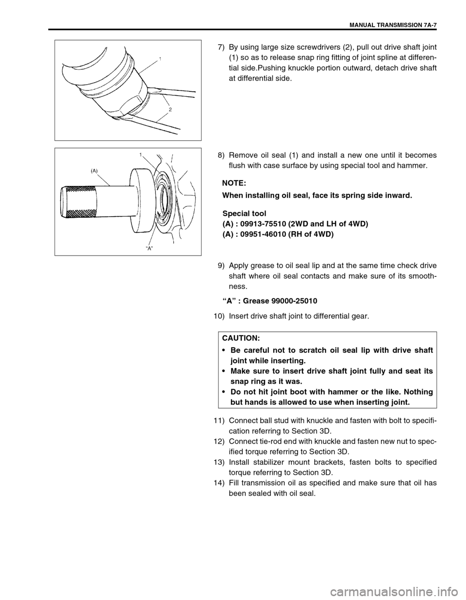
7) By using large size screwdrivers (2), pull out drive shaft joint
(1) so as to release snap ring fitting of joint spline at differen-
tial side.Pushing knuckle portion outward, detach drive shaft
at differential side.
8) Remove oil seal (1) and install a new one until it becomes
flush with case surface by using special tool and hammer.
Special tool
(A) : 09913-75510 (2WD and LH of 4WD)
(A) : 09951-46010 (RH of 4WD)
9) Apply grease to oil seal lip and at the same time check drive
shaft where oil seal contacts and make sure of its smooth-
ness.
“A” : Grease 99000-25010
10) Insert drive shaft joint to differential gear.
11) Connect ball stud with knuckle and fasten with bolt to specifi-
cation referring to Section 3D.
12) Connect tie-rod end with knuckle and fasten new nut to spec-
ified torque referring to Section 3D.
13) Install stabilizer mount brackets, fasten bolts to specified
torque referring to Section 3D.
14) Fill transmission oil as specified and make sure that oil has
been sealed with oil seal.
NOTE:
When installing oil seal, face its spring side inward.
CAUTION:
Be careful not to scratch oil seal lip with drive shaft
joint while inserting.
Make sure to insert drive shaft joint fully and seat its
snap ring as it was.
Do not hit joint boot with hammer or the like. Nothing
but hands is allowed to use when inserting joint.
Page 8 of 447
7A-8 MANUAL TRANSMISSION
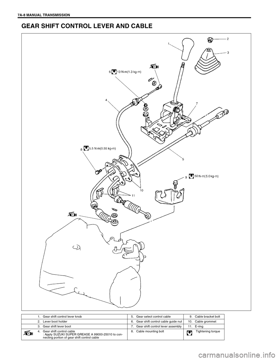
GEAR SHIFT CONTROL LEVER AND CABLE
1. Gear shift control lever knob 5. Gear select control cable 9. Cable bracket bolt
2. Lever boot holder 6. Gear shift control cable guide nut 10. Cable grommet
3. Gear shift lever boot 7. Gear shift control lever assembly 11. E-ring
4. Gear shift control cable
: Apply SUZUKI SUPER GREASE A 99000-25010 to con-
necting portion of gear shift control cable8. Cable mounting bolt Tightening torque
Page 9 of 447
MANUAL TRANSMISSION 7A-9
REMOVAL
1) Remove console box.
2) Disconnect gear shift and select control cables from gear
shift control lever assembly.
3) Remove gear shift control cable guide nuts and gear shift
lever assembly from body.
4) Disconnect shift and select cables from transmission.
5) Remove E-rings, cable grommet and cable clamp, and then
remove shift and select cables from body.
INSTALLATION
Reverse removal procedure for installation and note as follows.
• Tighten each bolts and nuts to specified torque referring to
previous figure.
Apply grease to turning or sliding portions.
Page 10 of 447
7A-10 MANUAL TRANSMISSION
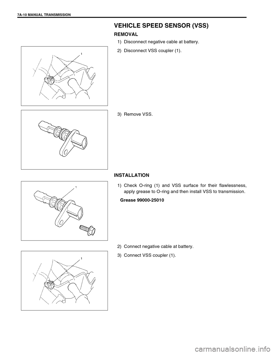
VEHICLE SPEED SENSOR (VSS)
REMOVAL
1) Disconnect negative cable at battery.
2) Disconnect VSS coupler (1).
3) Remove VSS.
INSTALLATION
1) Check O-ring (1) and VSS surface for their flawlessness,
apply grease to O-ring and then install VSS to transmission.
Grease 99000-25010
2) Connect negative cable at battery.
3) Connect VSS coupler (1).
Page 12 of 447
7A-12 MANUAL TRANSMISSION
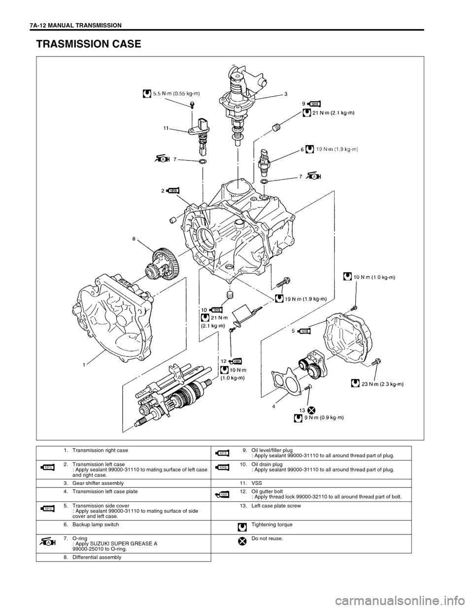
TRASMISSION CASE
1. Transmission right case 9. Oil level/filler plug
: Apply sealant 99000-31110 to all around thread part of plug.
2. Transmission left case
: Apply sealant 99000-31110 to mating surface of left case
and right case.10. Oil drain plug
: Apply sealant 99000-31110 to all around thread part of plug.
3. Gear shifter assembly 11. VSS
4. Transmission left case plate 12. Oil gutter bolt
: Apply thread lock 99000-32110 to all around thread part of bolt.
5. Transmission side cover
: Apply sealant 99000-31110 to mating surface of side
cover and left case.13. Left case plate screw
6. Backup lamp switch Tightening torque
7. O-ring
: Apply SUZUKI SUPER GREASE A
99000-25010 to O-ring.Do not reuse.
8. Differential assembly
Page 13 of 447

MANUAL TRANSMISSION 7A-13
INPUT & COUNTER SHAFT
1. Input shaft 13. Input shaft 5th gear 26. Countershaft
2. Oil seal
: Apply grease 99000-25010 to oil seal lip14. 5th gear spacer 27. Countershaft 1st gear
3. Input shaft right bearing 15. 5th gear needle bearing
(separated steel cage type)28. 1st gear synchronizer ring
4. Input shaft 3rd gear 16. 5th speed synchronizer ring 29. Low speed synchronizer spring
5. Needle bearing (resin cage type) 17. 5th synchronizer spring 30. Low speed sleeve & hub
5-1. Needle bearing (resin cage type) 18. 5th speed sleeve & hub 31. Low speed synchronizer key
6. High speed synchronizer ring 19. 5th synchronizer key 32. Circlip
7. High speed synchronizer spring 20. 5th synchronizer hub plate 33. 2nd gear synchronizer outer ring
8. High speed sleeve & hub 21. Circlip 34. Needle bearing
(separated steel cage type)
9. High speed synchronizer key 22. Reverse gear shaft 34-1. Needle bearing (steel cage type)
10. Circlip 23. Reverse idler gear 35. Countershaft 2nd gear
11. Input shaft 4th gear 24. Reverse shaft washer 36. Countershaft 3rd gear
12. Input shaft left bearing 25. Countershaft right bearing 37. 3rd & 4th gear spacer
Page 14 of 447
7A-14 MANUAL TRANSMISSION
GEAR SHIFTER & DIFFERENTIAL
38. Countershaft 4th gear 42. Countershaft nut
: After tightening nut to specified torque, caulk nut securely.46. 2nd gear synchronizer inner ring
39. Countershaft left bearing 43. Reverse shaft bolt
: Apply thread lock cement 99000-32110 to thread part of bolt.Tightening torque
40. Bearing set shim 44. Washer Do not reuse.
41. Countershaft 5th gear 45. Center cone Apply transmission oil.