turn signal bulb SUZUKI SWIFT 2000 1.G Transmission Service Workshop Manual
[x] Cancel search | Manufacturer: SUZUKI, Model Year: 2000, Model line: SWIFT, Model: SUZUKI SWIFT 2000 1.GPages: 447, PDF Size: 10.54 MB
Page 245 of 447

BODY ELECTRICAL SYSTEM 8-1
6F1
6F2
6G
6H
6K
7A
7A1
7B1
7C1
7D
7E
7F
8A
8
8D
8E
9
10
10A
10B
SECTION 8
BODY ELECTRICAL SYSTEM
CONTENTS
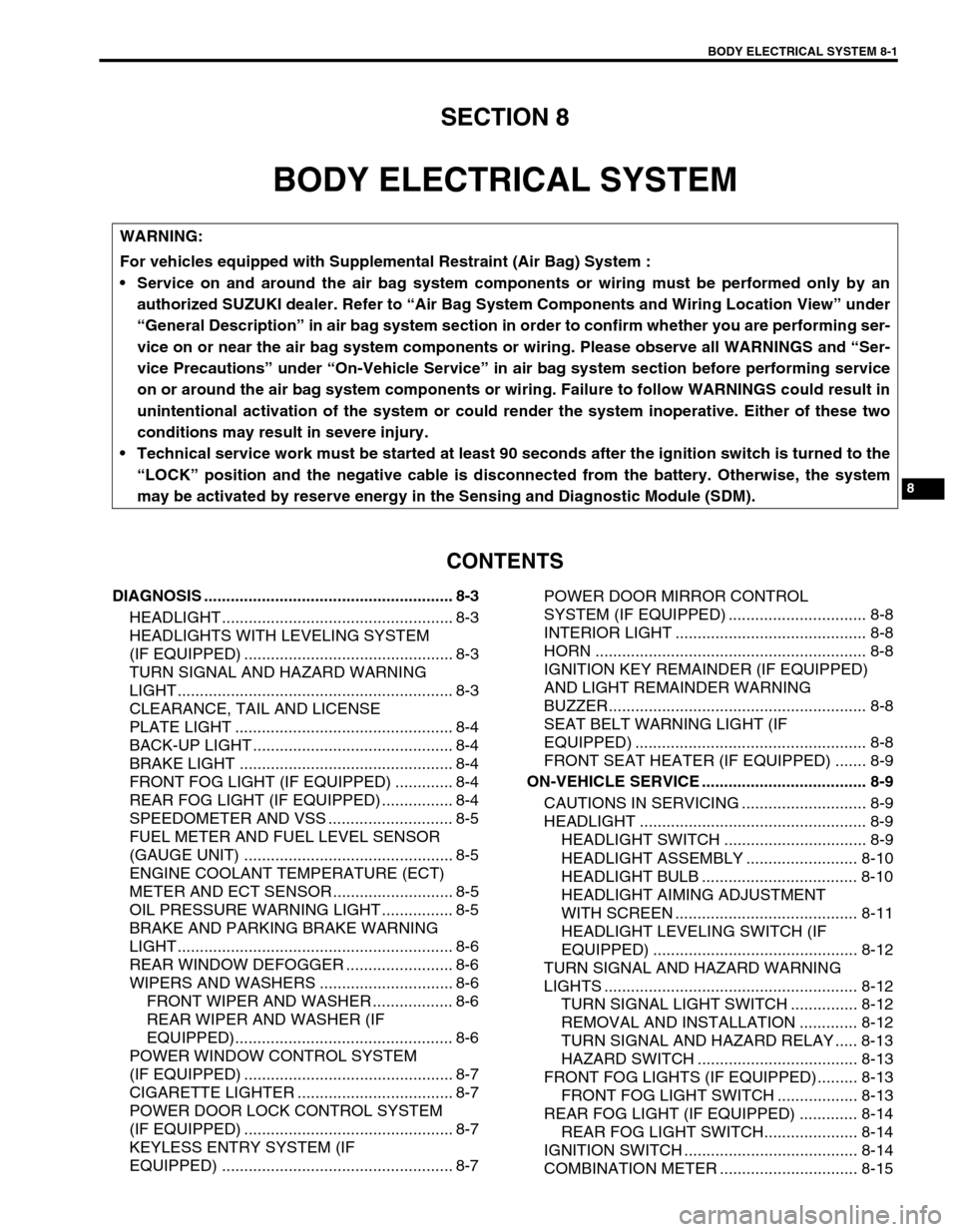
DIAGNOSIS ........................................................ 8-3
HEADLIGHT .................................................... 8-3
HEADLIGHTS WITH LEVELING SYSTEM
(IF EQUIPPED) ............................................... 8-3
TURN SIGNAL AND HAZARD WARNING
LIGHT .............................................................. 8-3
CLEARANCE, TAIL AND LICENSE
PLATE LIGHT ................................................. 8-4
BACK-UP LIGHT ............................................. 8-4
BRAKE LIGHT ................................................ 8-4
FRONT FOG LIGHT (IF EQUIPPED) ............. 8-4
REAR FOG LIGHT (IF EQUIPPED) ................ 8-4
SPEEDOMETER AND VSS ............................ 8-5
FUEL METER AND FUEL LEVEL SENSOR
(GAUGE UNIT) ............................................... 8-5
ENGINE COOLANT TEMPERATURE (ECT)
METER AND ECT SENSOR ........................... 8-5
OIL PRESSURE WARNING LIGHT ................ 8-5
BRAKE AND PARKING BRAKE WARNING
LIGHT .............................................................. 8-6
REAR WINDOW DEFOGGER ........................ 8-6
WIPERS AND WASHERS .............................. 8-6
FRONT WIPER AND WASHER .................. 8-6
REAR WIPER AND WASHER (IF
EQUIPPED)................................................. 8-6
POWER WINDOW CONTROL SYSTEM
(IF EQUIPPED) ............................................... 8-7
CIGARETTE LIGHTER ................................... 8-7
POWER DOOR LOCK CONTROL SYSTEM
(IF EQUIPPED) ............................................... 8-7
KEYLESS ENTRY SYSTEM (IF
EQUIPPED) .................................................... 8-7POWER DOOR MIRROR CONTROL
SYSTEM (IF EQUIPPED) ............................... 8-8
INTERIOR LIGHT ........................................... 8-8
HORN ............................................................. 8-8
IGNITION KEY REMAINDER (IF EQUIPPED)
AND LIGHT REMAINDER WARNING
BUZZER.......................................................... 8-8
SEAT BELT WARNING LIGHT (IF
EQUIPPED) .................................................... 8-8
FRONT SEAT HEATER (IF EQUIPPED) ....... 8-9
ON-VEHICLE SERVICE ..................................... 8-9
CAUTIONS IN SERVICING ............................ 8-9
HEADLIGHT ................................................... 8-9
HEADLIGHT SWITCH ................................ 8-9
HEADLIGHT ASSEMBLY ......................... 8-10
HEADLIGHT BULB ................................... 8-10
HEADLIGHT AIMING ADJUSTMENT
WITH SCREEN ......................................... 8-11
HEADLIGHT LEVELING SWITCH (IF
EQUIPPED) .............................................. 8-12
TURN SIGNAL AND HAZARD WARNING
LIGHTS ......................................................... 8-12
TURN SIGNAL LIGHT SWITCH ............... 8-12
REMOVAL AND INSTALLATION ............. 8-12
TURN SIGNAL AND HAZARD RELAY ..... 8-13
HAZARD SWITCH .................................... 8-13
FRONT FOG LIGHTS (IF EQUIPPED)......... 8-13
FRONT FOG LIGHT SWITCH .................. 8-13
REAR FOG LIGHT (IF EQUIPPED) ............. 8-14
REAR FOG LIGHT SWITCH..................... 8-14
IGNITION SWITCH ....................................... 8-14
COMBINATION METER ............................... 8-15 WARNING:
For vehicles equipped with Supplemental Restraint (Air Bag) System :
Service on and around the air bag system components or wiring must be performed only by an
authorized SUZUKI dealer. Refer to “Air Bag System Components and Wiring Location View” under
“General Description” in air bag system section in order to confirm whether you are performing ser-
vice on or near the air bag system components or wiring. Please observe all WARNINGS and “Ser-
vice Precautions” under “On-Vehicle Service” in air bag system section before performing service
on or around the air bag system components or wiring. Failure to follow WARNINGS could result in
unintentional activation of the system or could render the system inoperative. Either of these two
conditions may result in severe injury.
Technical service work must be started at least 90 seconds after the ignition switch is turned to the
“LOCK” position and the negative cable is disconnected from the battery. Otherwise, the system
may be activated by reserve energy in the Sensing and Diagnostic Module (SDM).
Page 247 of 447

BODY ELECTRICAL SYSTEM 8-3
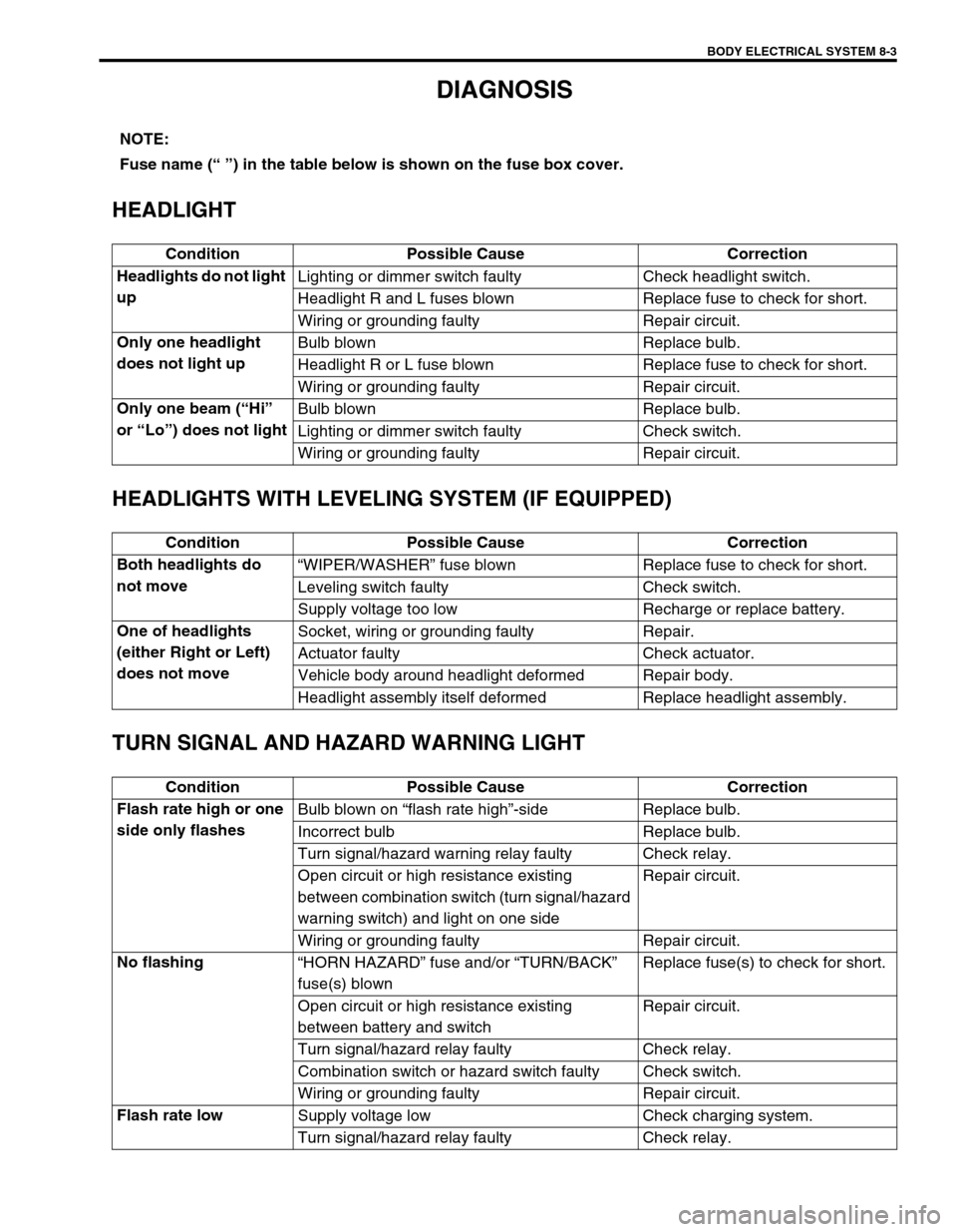
DIAGNOSIS
HEADLIGHT
HEADLIGHTS WITH LEVELING SYSTEM (IF EQUIPPED)
TURN SIGNAL AND HAZARD WARNING LIGHT
NOTE:
Fuse name (“ ”) in the table below is shown on the fuse box cover.
Condition Possible Cause Correction
Headlights do not light
upLighting or dimmer switch faulty Check headlight switch.
Headlight R and L fuses blown Replace fuse to check for short.
Wiring or grounding faulty Repair circuit.
Only one headlight
does not light upBulb blown Replace bulb.
Headlight R or L fuse blown Replace fuse to check for short.
Wiring or grounding faulty Repair circuit.
Only one beam (“Hi”
or “Lo”) does not lightBulb blown Replace bulb.
Lighting or dimmer switch faulty Check switch.
Wiring or grounding faulty Repair circuit.
Condition Possible Cause Correction
Both headlights do
not move“WIPER/WASHER” fuse blown Replace fuse to check for short.
Leveling switch faulty Check switch.
Supply voltage too low Recharge or replace battery.
One of headlights
(either Right or Left)
does not moveSocket, wiring or grounding faulty Repair.
Actuator faulty Check actuator.
Vehicle body around headlight deformed Repair body.
Headlight assembly itself deformed Replace headlight assembly.
Condition Possible Cause Correction
Flash rate high or one
side only flashesBulb blown on “flash rate high”-side Replace bulb.
Incorrect bulb Replace bulb.
Turn signal/hazard warning relay faulty Check relay.
Open circuit or high resistance existing
between combination switch (turn signal/hazard
warning switch) and light on one sideRepair circuit.
Wiring or grounding faulty Repair circuit.
No flashing
“HORN HAZARD” fuse and/or “TURN/BACK”
fuse(s) blownReplace fuse(s) to check for short.
Open circuit or high resistance existing
between battery and switchRepair circuit.
Turn signal/hazard relay faulty Check relay.
Combination switch or hazard switch faulty Check switch.
Wiring or grounding faulty Repair circuit.
Flash rate low
Supply voltage low Check charging system.
Turn signal/hazard relay faulty Check relay.
Page 249 of 447

BODY ELECTRICAL SYSTEM 8-5
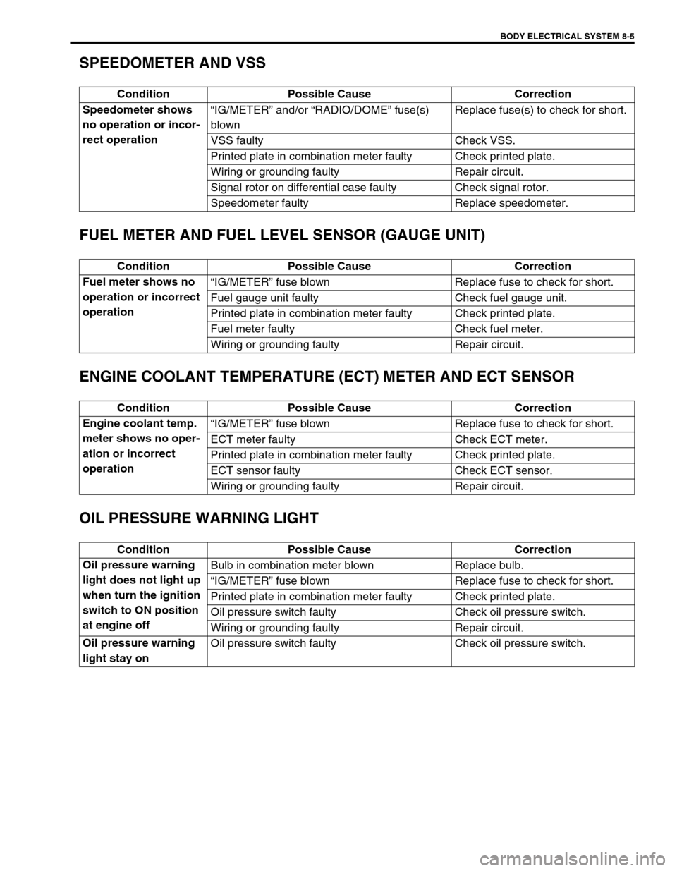
SPEEDOMETER AND VSS
FUEL METER AND FUEL LEVEL SENSOR (GAUGE UNIT)
ENGINE COOLANT TEMPERATURE (ECT) METER AND ECT SENSOR
OIL PRESSURE WARNING LIGHT
Condition Possible Cause Correction
Speedometer shows
no operation or incor-
rect operation“IG/METER” and/or “RADIO/DOME” fuse(s)
blownReplace fuse(s) to check for short.
VSS faulty Check VSS.
Printed plate in combination meter faulty Check printed plate.
Wiring or grounding faulty Repair circuit.
Signal rotor on differential case faulty Check signal rotor.
Speedometer faulty Replace speedometer.
Condition Possible Cause Correction
Fuel meter shows no
operation or incorrect
operation“IG/METER” fuse blown Replace fuse to check for short.
Fuel gauge unit faulty Check fuel gauge unit.
Printed plate in combination meter faulty Check printed plate.
Fuel meter faulty Check fuel meter.
Wiring or grounding faulty Repair circuit.
Condition Possible Cause Correction
Engine coolant temp.
meter shows no oper-
ation or incorrect
operation“IG/METER” fuse blown Replace fuse to check for short.
ECT meter faulty Check ECT meter.
Printed plate in combination meter faulty Check printed plate.
ECT sensor faulty Check ECT sensor.
Wiring or grounding faulty Repair circuit.
Condition Possible Cause Correction
Oil pressure warning
light does not light up
when turn the ignition
switch to ON position
at engine offBulb in combination meter blown Replace bulb.
“IG/METER” fuse blown Replace fuse to check for short.
Printed plate in combination meter faulty Check printed plate.
Oil pressure switch faulty Check oil pressure switch.
Wiring or grounding faulty Repair circuit.
Oil pressure warning
light stay onOil pressure switch faulty Check oil pressure switch.
Page 257 of 447

BODY ELECTRICAL SYSTEM 8-13
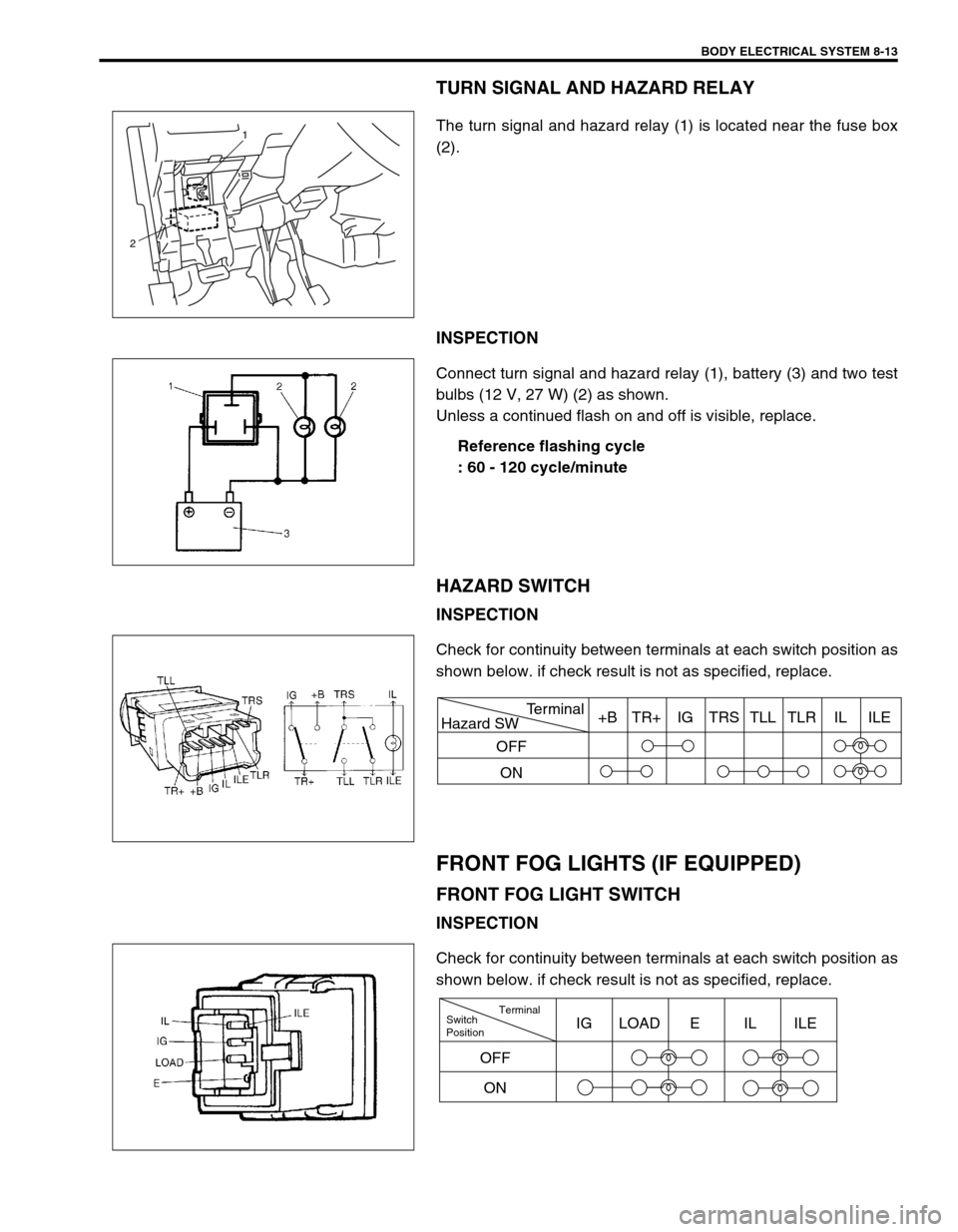
TURN SIGNAL AND HAZARD RELAY
The turn signal and hazard relay (1) is located near the fuse box
(2).
INSPECTION
Connect turn signal and hazard relay (1), battery (3) and two test
bulbs (12 V, 27 W) (2) as shown.
Unless a continued flash on and off is visible, replace.
Reference flashing cycle
: 60 - 120 cycle/minute
HAZARD SWITCH
INSPECTION
Check for continuity between terminals at each switch position as
shown below. if check result is not as specified, replace.
FRONT FOG LIGHTS (IF EQUIPPED)
FRONT FOG LIGHT SWITCH
INSPECTION
Check for continuity between terminals at each switch position as
shown below. if check result is not as specified, replace.
1
2
Hazard SWTerminal
OFF
ON+B TR+ IG TRS TLL TLR IL ILE
Switch
PositionTerminal
ONIG LOAD E IL ILE
OFF