washer fluid SUZUKI SWIFT 2000 1.G Transmission Service Workshop Manual
[x] Cancel search | Manufacturer: SUZUKI, Model Year: 2000, Model line: SWIFT, Model: SUZUKI SWIFT 2000 1.GPages: 447, PDF Size: 10.54 MB
Page 130 of 447
7B-88 AUTOMATIC TRANSMISSION (4 A/T)
DISASSEMBLY/ASSEMBLY OF SUBASSEMBLY
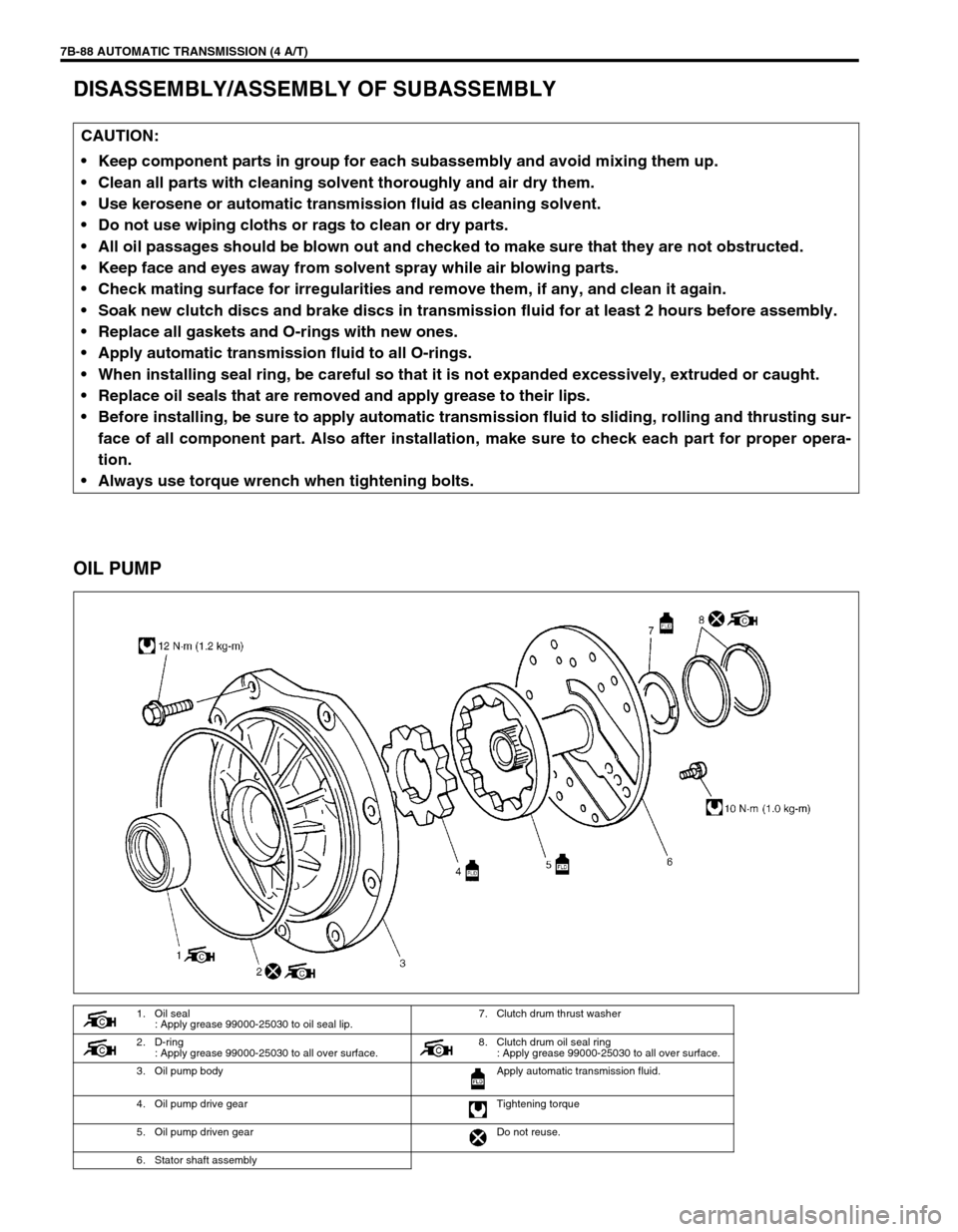
OIL PUMP
CAUTION:
Keep component parts in group for each subassembly and avoid mixing them up.
Clean all parts with cleaning solvent thoroughly and air dry them.
Use kerosene or automatic transmission fluid as cleaning solvent.
Do not use wiping cloths or rags to clean or dry parts.
All oil passages should be blown out and checked to make sure that they are not obstructed.
Keep face and eyes away from solvent spray while air blowing parts.
Check mating surface for irregularities and remove them, if any, and clean it again.
Soak new clutch discs and brake discs in transmission fluid for at least 2 hours before assembly.
Replace all gaskets and O-rings with new ones.
Apply automatic transmission fluid to all O-rings.
When installing seal ring, be careful so that it is not expanded excessively, extruded or caught.
Replace oil seals that are removed and apply grease to their lips.
Before installing, be sure to apply automatic transmission fluid to sliding, rolling and thrusting sur-
face of all component part. Also after installation, make sure to check each part for proper opera-
tion.
Always use torque wrench when tightening bolts.
1. Oil seal
: Apply grease 99000-25030 to oil seal lip.7. Clutch drum thrust washer
2. D-ring
: Apply grease 99000-25030 to all over surface. 8. Clutch drum oil seal ring
: Apply grease 99000-25030 to all over surface.
3. Oil pump body Apply automatic transmission fluid.
4. Oil pump drive gear Tightening torque
5. Oil pump driven gear Do not reuse.
6. Stator shaft assembly
Page 148 of 447
7B-106 AUTOMATIC TRANSMISSION (4 A/T)
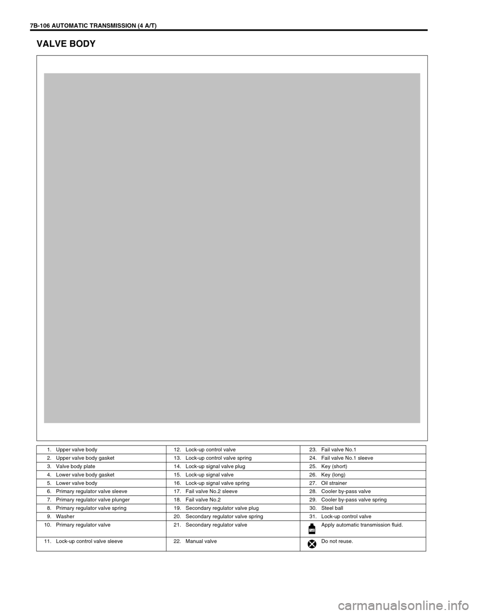
VALVE BODY
1. Upper valve body 12. Lock-up control valve 23. Fail valve No.1
2. Upper valve body gasket 13. Lock-up control valve spring 24. Fail valve No.1 sleeve
3. Valve body plate 14. Lock-up signal valve plug 25. Key (short)
4. Lower valve body gasket 15. Lock-up signal valve 26. Key (long)
5. Lower valve body 16. Lock-up signal valve spring 27. Oil strainer
6. Primary regulator valve sleeve 17. Fail valve No.2 sleeve 28. Cooler by-pass valve
7. Primary regulator valve plunger 18. Fail valve No.2 29. Cooler by-pass valve spring
8. Primary regulator valve spring 19. Secondary regulator valve plug 30. Steel ball
9. Washer 20. Secondary regulator valve spring 31. Lock-up control valve
10. Primary regulator valve 21. Secondary regulator valve Apply automatic transmission fluid.
11. Lock-up control valve sleeve 22. Manual valve Do not reuse.
Page 151 of 447
AUTOMATIC TRANSMISSION (4 A/T) 7B-109
ASSEMBLY
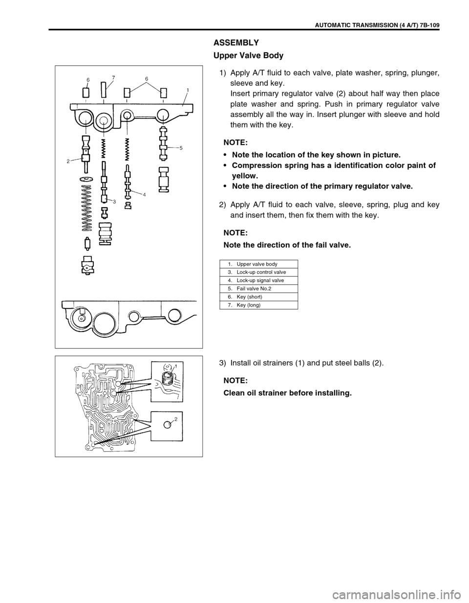
Upper Valve Body
1) Apply A/T fluid to each valve, plate washer, spring, plunger,
sleeve and key.
Insert primary regulator valve (2) about half way then place
plate washer and spring. Push in primary regulator valve
assembly all the way in. Insert plunger with sleeve and hold
them with the key.
2) Apply A/T fluid to each valve, sleeve, spring, plug and key
and insert them, then fix them with the key.
3) Install oil strainers (1) and put steel balls (2).NOTE:
Note the location of the key shown in picture.
Compression spring has a identification color paint of
yellow.
Note the direction of the primary regulator valve.
NOTE:
Note the direction of the fail valve.
1. Upper valve body
3. Lock-up control valve
4. Lock-up signal valve
5. Fail valve No.2
6. Key (short)
7. Key (long)
NOTE:
Clean oil strainer before installing.
Page 154 of 447
7B-112 AUTOMATIC TRANSMISSION (4 A/T)
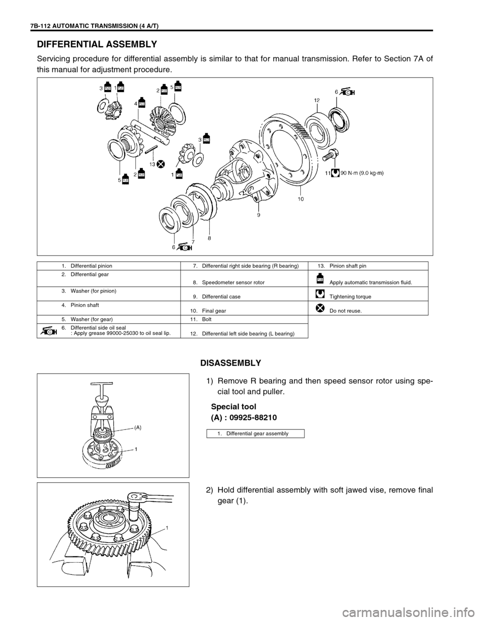
DIFFERENTIAL ASSEMBLY
Servicing procedure for differential assembly is similar to that for manual transmission. Refer to Section 7A of
this manual for adjustment procedure.
DISASSEMBLY
1) Remove R bearing and then speed sensor rotor using spe-
cial tool and puller.
Special tool
(A) : 09925-88210
2) Hold differential assembly with soft jawed vise, remove final
gear (1).
1. Differential pinion 7. Differential right side bearing (R bearing) 13. Pinion shaft pin
2. Differential gear
8. Speedometer sensor rotor Apply automatic transmission fluid.
3. Washer (for pinion)
9. Differential case Tightening torque
4. Pinion shaft
10. Final gear Do not reuse.
5. Washer (for gear) 11. Bolt
6. Differential side oil seal
: Apply grease 99000-25030 to oil seal lip.
12. Differential left side bearing (L bearing)
1. Differential gear assembly
Page 246 of 447
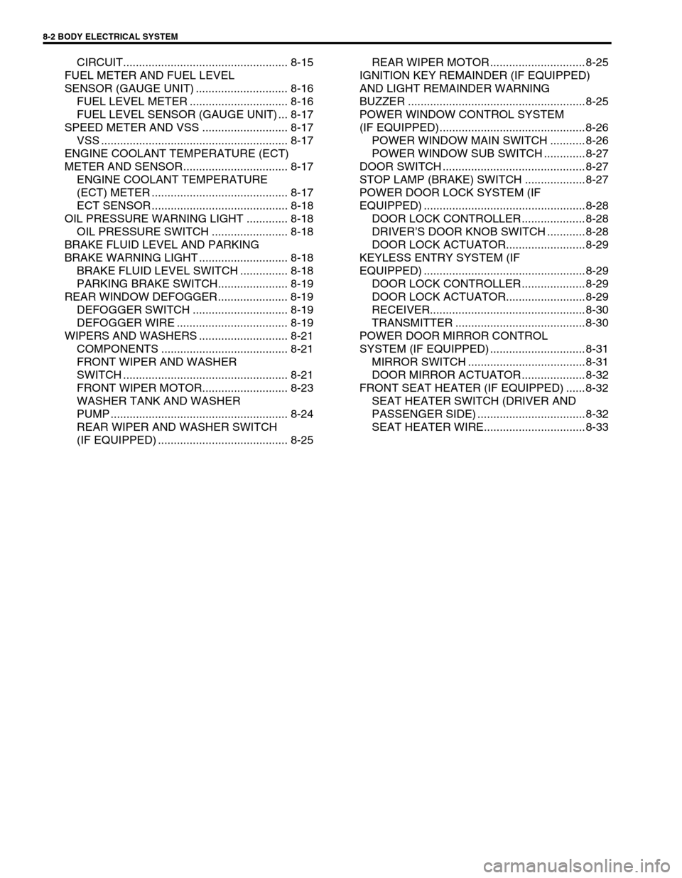
8-2 BODY ELECTRICAL SYSTEM
CIRCUIT.................................................... 8-15
FUEL METER AND FUEL LEVEL
SENSOR (GAUGE UNIT) ............................. 8-16
FUEL LEVEL METER ............................... 8-16
FUEL LEVEL SENSOR (GAUGE UNIT) ... 8-17
SPEED METER AND VSS ........................... 8-17
VSS ........................................................... 8-17
ENGINE COOLANT TEMPERATURE (ECT)
METER AND SENSOR................................. 8-17
ENGINE COOLANT TEMPERATURE
(ECT) METER ........................................... 8-17
ECT SENSOR ........................................... 8-18
OIL PRESSURE WARNING LIGHT ............. 8-18
OIL PRESSURE SWITCH ........................ 8-18
BRAKE FLUID LEVEL AND PARKING
BRAKE WARNING LIGHT ............................ 8-18
BRAKE FLUID LEVEL SWITCH ............... 8-18
PARKING BRAKE SWITCH...................... 8-19
REAR WINDOW DEFOGGER...................... 8-19
DEFOGGER SWITCH .............................. 8-19
DEFOGGER WIRE ................................... 8-19
WIPERS AND WASHERS ............................ 8-21
COMPONENTS ........................................ 8-21
FRONT WIPER AND WASHER
SWITCH .................................................... 8-21
FRONT WIPER MOTOR........................... 8-23
WASHER TANK AND WASHER
PUMP ........................................................ 8-24
REAR WIPER AND WASHER SWITCH
(IF EQUIPPED) ......................................... 8-25REAR WIPER MOTOR .............................. 8-25
IGNITION KEY REMAINDER (IF EQUIPPED)
AND LIGHT REMAINDER WARNING
BUZZER ........................................................ 8-25
POWER WINDOW CONTROL SYSTEM
(IF EQUIPPED).............................................. 8-26
POWER WINDOW MAIN SWITCH ........... 8-26
POWER WINDOW SUB SWITCH ............. 8-27
DOOR SWITCH ............................................. 8-27
STOP LAMP (BRAKE) SWITCH ................... 8-27
POWER DOOR LOCK SYSTEM (IF
EQUIPPED) ................................................... 8-28
DOOR LOCK CONTROLLER .................... 8-28
DRIVER’S DOOR KNOB SWITCH ............ 8-28
DOOR LOCK ACTUATOR......................... 8-29
KEYLESS ENTRY SYSTEM (IF
EQUIPPED) ................................................... 8-29
DOOR LOCK CONTROLLER .................... 8-29
DOOR LOCK ACTUATOR......................... 8-29
RECEIVER................................................. 8-30
TRANSMITTER ......................................... 8-30
POWER DOOR MIRROR CONTROL
SYSTEM (IF EQUIPPED) .............................. 8-31
MIRROR SWITCH ..................................... 8-31
DOOR MIRROR ACTUATOR .................... 8-32
FRONT SEAT HEATER (IF EQUIPPED) ...... 8-32
SEAT HEATER SWITCH (DRIVER AND
PASSENGER SIDE) .................................. 8-32
SEAT HEATER WIRE................................ 8-33
Page 250 of 447
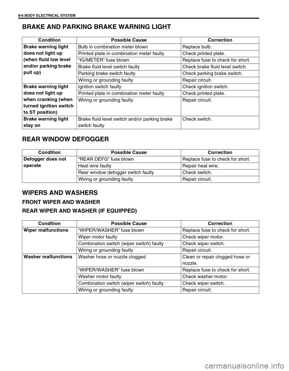
8-6 BODY ELECTRICAL SYSTEM
BRAKE AND PARKING BRAKE WARNING LIGHT
REAR WINDOW DEFOGGER
WIPERS AND WASHERS
FRONT WIPER AND WASHER
REAR WIPER AND WASHER (IF EQUIPPED)
Condition Possible Cause Correction
Brake warning light
does not light up
(when fluid low level
and/or parking brake
pull up)Bulb in combination meter blown Replace bulb.
Printed plate in combination meter faulty Check printed plate.
“IG/METER” fuse blown Replace fuse to check for short.
Brake fluid level switch faulty Check brake fluid level switch.
Parking brake switch faulty Check parking brake switch.
Wiring or grounding faulty Repair circuit.
Brake warning light
does not light up
when cranking (when
turned ignition switch
to ST position)Ignition switch faulty Check ignition switch.
Printed plate in combination meter faulty Check printed plate.
Wiring or grounding faulty Repair circuit.
Brake warning light
stay onBrake fluid level switch and/or parking brake
switch faultyCheck switch.
Condition Possible Cause Correction
Defogger does not
operate“REAR DEFG” fuse blown Replace fuse to check for short.
Heat wire faulty Repair heat wire.
Rear window defogger switch faulty Check switch.
Wiring or grounding faulty Repair circuit.
Condition Possible Cause Correction
Wiper malfunctions
“WIPER/WASHER” fuse blown Replace fuse to check for short.
Wiper motor faulty Check wiper motor.
Combination switch (wiper switch) faulty Check wiper switch.
Wiring or grounding faulty Repair circuit.
Washer malfunctions
Washer hose or nozzle clogged Clean or repair clogged hose or
nozzle.
“WIPER/WASHER” fuse blown Replace fuse to check for short.
Washer motor faulty Check washer motor.
Combination switch (wiper switch) faulty Check wiper switch.
Wiring or grounding faulty Repair circuit.