egr SUZUKI SWIFT 2005 2.G Service Service Manual
[x] Cancel search | Manufacturer: SUZUKI, Model Year: 2005, Model line: SWIFT, Model: SUZUKI SWIFT 2005 2.GPages: 1496, PDF Size: 34.44 MB
Page 302 of 1496

Downloaded from www.Manualslib.com manuals search engine 1D-17 Engine Mechanical:
Engine Assembly Removal and InstallationS7RS0B1406011
NOTE
After replacing electric throttle body
assembly, perform calibration of throttle
valve referring to “Electric Throttle Body
System Calibration in Section 1C”.
Removal1) Relieve fuel pressure according to “Fuel Pressure Relief Procedure in Section 1G”.
2) Disconnect negative and pos itive cable at battery.
3) Remove battery and tray.
4) Remove engine hood after disconnecting windshield washer hose.
5) Remove right and left side engine under covers.
6) Remove A/C compressor belt by referring to “Compressor Drive Belt Remo val and Installation in
Section 7B” or “Compressor Drive Belt Removal and
Installation in Section 7B”.
7) Drain engine oil, transaxle oil and coolant.
8) Remove cowl top plate referring to “Cowl Top Components in Section 9K”.
9) Remove air cleaner assembly referring to “Air Cleaner Components”.
10) With hose connected, detach A/C compressor from its bracket (A/C model) referring to “Compressor
Assembly Removal and Installation in Section 7B” or
“Compressor Assembly Removal and Installation in
Section 7B”.
CAUTION!
Suspend removed A/C compressor at a place
where no damage will be caused during
removal and installation of engine assembly.
11) Remove intake manifold rear stiffener (1) from intake manifold and cylinder block. 12) Disconnect the following electric wires:
• MAP sensor (1)
• ECT sensor (2)
•EGR valve (3)
• CMP sensor (4)
• Electric throttle body assembly (5)
• Ignition coil assembly (6)
• Injectors (7)
• Heated oxygen sensor No. 2 (8) and No. 1 (9)
• Oil control valve (10)
• Engine oil pressure switch (11)
• CKP sensor (12)
• Knock sensor (13)
• Back up light switch (14)
• Generator (15)
• Starting motor (16)
• Ground terminal (17) from intake manifold
• Battery ground terminal (18) from exhaust manifold
• Battery ground cable (19) from transaxle
• Magnet clutch switch of A/C compressor (A/C model)
• Each wire harness clamps
• Output shaft speed sensor (VSS) (34) (A/T model)
• Solenoid valve (33) (A/T model)
• Transmission range sensor (32) (A/T model)
• Input shaft speed sensor (31) (A/T model)
13) Remove fuse box from its bracket.
14) Disconnect the following cables: • Gear select control cable (23) (M/T model)
• Gear shift control cable (24) (M/T model)
• A/T select cable (A/T model)
15) Disconnect the following hoses: • Brake booster hose (26) from intake manifold
• Radiator inlet and outlet hoses (20) from each pipe
• Heater inlet and outlet hoses (21) from each pipe
• Fuel feed hoses (22) from fuel feed pipe
• EVAP canister purge valve hose (30) from purge pipe
• A/T fluid cooler hoses (A/T model)
16) With hose connected, detach clutch operating cylinder (25). (M/T model)
CAUTION!
Suspend removed clutch operating cylinder
at a place where no damage will be caused
during removal and installation of engine
assembly.
1
I6RS0B141014-01
Page 326 of 1496
Downloaded from www.Manualslib.com manuals search engine 1D-41 Engine Mechanical:
Valve head radial runout
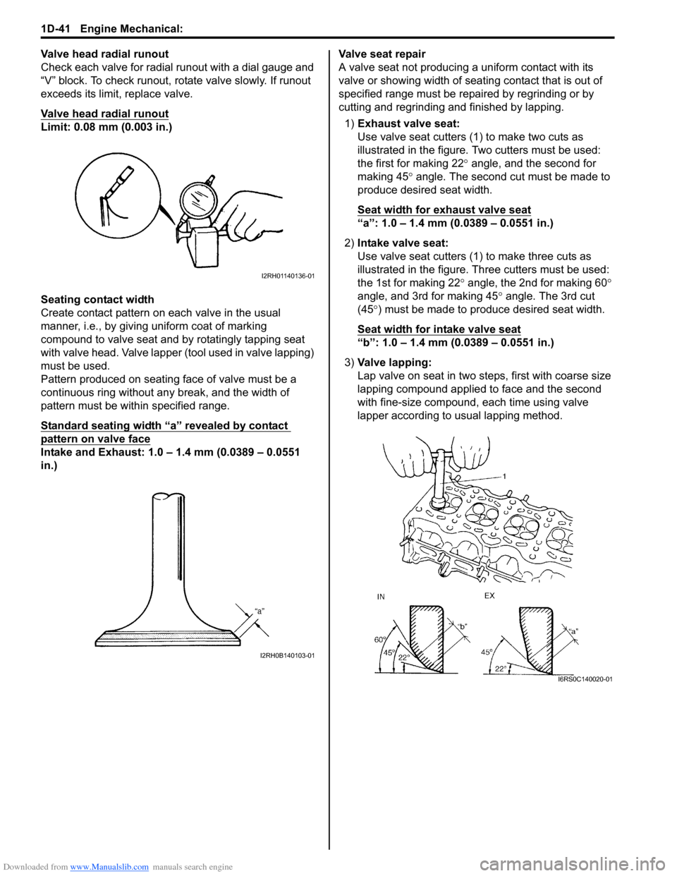
Check each valve for radial runout with a dial gauge and
“V” block. To check runout, rotate valve slowly. If runout
exceeds its limit, replace valve.
Valve head radial runout
Limit: 0.08 mm (0.003 in.)
Seating contact width
Create contact pattern on each valve in the usual
manner, i.e., by giving uniform coat of marking
compound to valve seat and by rotatingly tapping seat
with valve head. Valve lapper (tool used in valve lapping)
must be used.
Pattern produced on seating face of valve must be a
continuous ring without any break, and the width of
pattern must be within specified range.
Standard seating width “a” revealed by contact
pattern on valve face
Intake and Exhaust: 1.0 – 1.4 mm (0.0389 – 0.0551
in.)Valve seat repair
A valve seat not producing
a uniform contact with its
valve or showing width of seating contact that is out of
specified range must be repaired by regrinding or by
cutting and regrinding and finished by lapping.
1) Exhaust valve seat:
Use valve seat cutters (1 ) to make two cuts as
illustrated in the figure. Two cutters must be used:
the first for making 22 ° angle, and the second for
making 45 ° angle. The second cut must be made to
produce desired seat width.
Seat width for exhaust valve seat
“a”: 1.0 – 1.4 mm (0.0389 – 0.0551 in.)
2) Intake valve seat:
Use valve seat cutters (1) to make three cuts as
illustrated in the figure. Th ree cutters must be used:
the 1st for making 22 ° angle, the 2nd for making 60 °
angle, and 3rd for making 45 ° angle. The 3rd cut
(45 °) must be made to produce desired seat width.
Seat width for intake valve seat
“b”: 1.0 – 1.4 mm (0.0389 – 0.0551 in.)
3) Valve lapping:
Lap valve on seat in two steps, first with coarse size
lapping compound applied to face and the second
with fine-size compound, each time using valve
lapper according to usual lapping method.
I2RH01140136-01
I2RH0B140103-01
I6RS0C140020-01
Page 335 of 1496
Downloaded from www.Manualslib.com manuals search engine Engine Mechanical: 1D-50
Connecting rod bearing cap bolt deformation
(Plastic deformation tightening bolt)
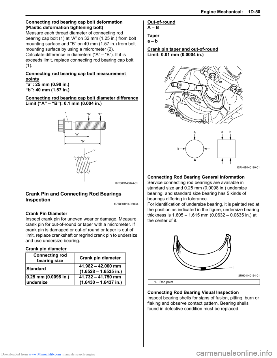
Measure each thread diameter of connecting rod
bearing cap bolt (1) at “A” on 32 mm (1.25 in.) from bolt
mounting surface and “B” on 40 mm (1.57 in.) from bolt
mounting surface by using a micrometer (2).
Calculate difference in diameters (“A” – “B”). If it is
exceeds limit, replace connecting rod bearing cap bolt
(1).
Connecting rod bearing cap bolt measurement
points
“a”: 25 mm (0.98 in.)
“b”: 40 mm (1.57 in.)
Connecting rod bearing cap bolt diameter difference
Limit (“A” – “B”): 0.1 mm (0.004 in.)
Crank Pin and Connecting Rod Bearings
Inspection
S7RS0B1406034
Crank Pin Diameter
Inspect crank pin for uneven wear or damage. Measure
crank pin for out-of-round or taper with a micrometer. If
crank pin is damaged or out-of round or taper is out of
limit, replace crankshaft or regrind crank pin to undersize
and use undersize bearing.
Crank pin diameter
Out-of-round
A – B
Ta p e r
a – b
Crank pin taper and out-of-round
Limit: 0.01 mm (0.0004 in.)
Connecting Rod Bearing General Information
Service connecting rod be arings are available in
standard size and 0.25 mm (0.0098 in.) undersize
bearing, and standard size bearing has 5 kinds of
bearings differing in tolerance.
For identification of undersize bearing, it is painted red at
the position as indicated in the figure, undersize bearing
thickness is 1.605 – 1.615 mm (0.0632 – 0.0635 in.) at
the center of it.
Connecting Rod Bearing Visual Inspection
Inspect bearing shells for signs of fusion, pitting, burn or
flaking and observe contact pattern. Bearing shells
found in defective condition must be replaced.
Connecting rod
bearing size Crank pin diameter
Standard 41.982 – 42.000 mm
(1.6528 – 1.6535 in.)
0.25 mm (0.0098 in.)
undersize 41.732 – 41.750 mm
(1.6430 – 1.6437 in.)
I6RS0C140024-01
1. Red paint
I2RH0B140120-01
I2RH01140164-01
Page 336 of 1496
Downloaded from www.Manualslib.com manuals search engine 1D-51 Engine Mechanical:
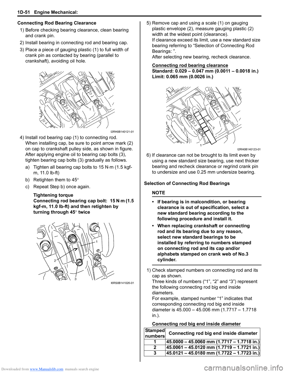
Connecting Rod Bearing Clearance1) Before checking bearing clearance, clean bearing and crank pin.
2) Install bearing in connecting rod and bearing cap.
3) Place a piece of gauging plastic (1) to full width of crank pin as contacted by bearing (parallel to
crankshaft), avoiding oil hole.
4) Install rod bearing cap (1) to connecting rod. When installing cap, be sure to point arrow mark (2)
on cap to crankshaft pulley side, as shown in figure.
After applying engine oil to bearing cap bolts (3),
tighten bearing cap bolts (3) gradually as follows.
a) Tighten all bearing cap bolts to 15 N ⋅m (1.5 kgf-
m, 11.0 lb-ft)
b) Retighten them to 45°
c) Repeat Step b) once again.
Tightening torque
Connecting rod bearing cap bolt: 15 N ⋅m (1.5
kgf-m, 11.0 lb-ft) and then retighten by
turning through 45 ° twice 5) Remove cap and using a scale (1) on gauging
plastic envelope (2), measure gauging plastic (2)
width at the widest point (clearance).
If clearance exceed its limit, use a new standard size
bearing referring to “Selection of Connecting Rod
Bearings: ”.
After selecting new bearing, recheck clearance.
Connecting rod bearing clearance
Standard: 0.029 – 0.047 mm (0.0011 – 0.0018 in.)
Limit: 0.065 mm (0.0026 in.)
6) If clearance can not be brought to its limit even by using a new standard size bearing, use next thicker
bearing and recheck clearance or regrind crank pin
to undersize and use 0.25 mm undersize bearing.
Selection of Connecting Rod Bearings
NOTE
• If bearing is in malcondition, or bearing clearance is out of specification, select a
new standard bearing according to the
following procedure and install it.
• When replacing crankshaft or connecting rod and its bearing due to any reason,
select new standard bearings to be
installed by referring to numbers stamped
on connecting rod and its cap and/or
alphabets stamped on crank web of No.3
cylinder.
1) Check stamped numbers on connecting rod and its cap as shown.
Three kinds of numbers (“1”, “2” and “3”) represent
the following connecting rod big end inside
diameters.
For example, stamped number “1” indicates that
corresponding connecting rod big end inside
diameter is 45.000 – 45.006 mm (1.7717 – 1.7718
in.).
Connecting rod big end inside diameter
I2RH0B140121-01
I6RS0B141026-01
Stamped
numbers Connecting rod big end inside diameter
1 45.0000 – 45.0060 mm (1.7717 – 1.7718 in.)
2 45.0061 – 45.0120 mm (1.7719 – 1.7721 in.)
3 45.0121 – 45.0180 mm (1.7722 – 1.7723 in.)
I2RH0B140123-01
Page 343 of 1496
Downloaded from www.Manualslib.com manuals search engine Engine Mechanical: 1D-58
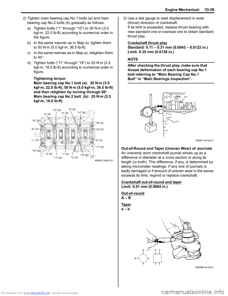
2) Tighten main bearing cap No.1 bolts (a) and main bearing cap No.2 bolts (b ) gradually as follows.
a) Tighten bolts (“1” through “10”) to 30 N ⋅m (3.0
kgf-m, 22.0 lb-ft) according to numerical order in
the figure.
b) In the same manner as in Step a), tighten them to 50 N ⋅m (5.0 kgf-m, 36.5 lb-ft).
c) In the same manner as in Step a), retighten them to 60 °.
d) Tighten bolts (“11” through “18”) to 25 N ⋅m (2.5
kgf-m, 18.0 lb-ft) according to numerical order in
figure.
Tightening torque
Main bearing cap No.1 bolt (a): 30 N ⋅m (3.0
kgf-m, 22.0 lb-ft), 50 N ⋅m (5.0 kgf-m, 36.5 lb-ft)
and then retighten by turning through 60 °
Main bearing cap No.2 bolt (b): 25 N·m (2.5
kgf-m, 18.0 lb-ft) 3) Use a dial gauge to read displacement in axial
(thrust) direction of crankshaft.
If its limit is exceeded, replace thrust bearing with
new standard one or oversize one to obtain standard
thrust play.
Crankshaft thrust play
Standard: 0.11 – 0.31 mm (0.0043 – 0.0122 in.)
Limit: 0.35 mm (0.0138 in.)
NOTE
After checking the thrust play, make sure that
thread deformation of each bearing cap No.1
bolt referring to “Main Bearing Cap No.1
Bolt” in “Main Bear ings Inspection”.
Out-of-Round and Taper (Uneven Wear) of Journals
An unevenly worn crankshaft journal shows up as a
difference in diameter at a cross section or along its
length (or both). This difference, if any, is determined by
taking micrometer readings. If any one of journals is
badly damaged or if amount of uneven wear in the sense
exceeds its limit, regrind or replace crankshaft.
Crankshaft out-of-round and taper
Limit: 0.01 mm (0.0004 in.)
Out-of-round
A – B
Ta p e r
a – b
I6RS0C140027-01
I2RH01140183-01
I2RH0B140138-01
Page 344 of 1496
Downloaded from www.Manualslib.com manuals search engine 1D-59 Engine Mechanical:
Main Bearings InspectionS7RS0B1406038
General Information
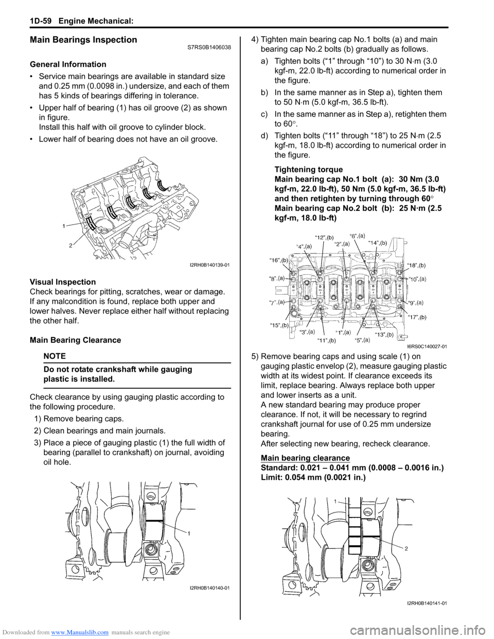
• Service main bearings are available in standard size and 0.25 mm (0.0098 in.) undersize, and each of them
has 5 kinds of bearings differing in tolerance.
• Upper half of bearing (1) has oil groove (2) as shown in figure.
Install this half with o il groove to cylinder block.
• Lower half of bearing does not have an oil groove.
Visual Inspection
Check bearings for pitting, scratches, wear or damage.
If any malcondition is foun d, replace both upper and
lower halves. Never replace either half without replacing
the other half.
Main Bearing Clearance
NOTE
Do not rotate crankshaft while gauging
plastic is installed.
Check clearance by using ga uging plastic according to
the following procedure.
1) Remove bearing caps.
2) Clean bearings and main journals.
3) Place a piece of gauging plastic (1) the full width of bearing (parallel to crankshaft) on journal, avoiding
oil hole. 4) Tighten main bearing cap No.1 bolts (a) and main
bearing cap No.2 bolts (b) gradually as follows.
a) Tighten bolts (“1” through “10”) to 30 N ⋅m (3.0
kgf-m, 22.0 lb-ft) according to numerical order in
the figure.
b) In the same manner as in Step a), tighten them to 50 N ⋅m (5.0 kgf-m, 36.5 lb-ft).
c) In the same manner as in Step a), retighten them to 60 °.
d) Tighten bolts (“11” through “18”) to 25 N ⋅m (2.5
kgf-m, 18.0 lb-ft) according to numerical order in
the figure.
Tightening torque
Main bearing cap No.1 bolt (a): 30 Nm (3.0
kgf-m, 22.0 lb-ft), 50 Nm (5.0 kgf-m, 36.5 lb-ft)
and then retighten by turning through 60°
Main bearing cap No.2 bolt (b): 25 N·m (2.5
kgf-m, 18.0 lb-ft)
5) Remove bearing caps and using scale (1) on gauging plastic envelop (2), measure gauging plastic
width at its widest point. If clearance exceeds its
limit, replace bearing. Always replace both upper
and lower inserts as a unit.
A new standard bearing may produce proper
clearance. If not, it will be necessary to regrind
crankshaft journal for use of 0.25 mm undersize
bearing.
After selecting new bearing, recheck clearance.
Main bearing clearance
Standard: 0.021 – 0.041 mm (0.0008 – 0.0016 in.)
Limit: 0.054 mm (0.0021 in.)
I2RH0B140139-01
I2RH0B140140-01
I6RS0C140027-01
I2RH0B140141-01
Page 347 of 1496
Downloaded from www.Manualslib.com manuals search engine Engine Mechanical: 1D-62
Undersize bearing (0.25 mm (0.0098 in.))
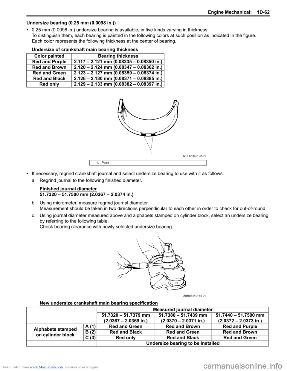
• 0.25 mm (0.0098 in.) undersize bearing is available, in five kinds varying in thickness.
To distinguish them, each bearing is painted in the following colors at such position as indicated in the figure.
Each color represents the following thickness at the center of bearing.
Undersize of crankshaft main bearing thickness
• If necessary, regrind crankshaft journal and sele ct undersize bearing to use with it as follows.
a. Regrind journal to the following finished diameter.
Finished journal diameter
51.7320 – 51.7500 mm (2.0367 – 2.0374 in.)
b. Using micrometer, measure regrind journal diameter. Measurement should be taken in two directions perpendicular to each other in order to check for out-of-round.
c. Using journal diameter measured above and alphabets stamped on cylinder block, select an undersize bearing
by referring to the following table.
Check bearing clearance with ne wly selected undersize bearing.
New undersize crankshaft main bearing specification
Color painted Bearing thickness
Red and Purple 2.117 – 2.121 mm (0.08335 – 0.08350 in.)
Red and Brown 2.120 – 2.124 mm (0.08347 – 0.08362 in.) Red and Green 2.123 – 2.127 mm (0.08359 – 0.08374 in.) Red and Black 2.126 – 2.130 mm (0.08371 – 0.08385 in.) Red only 2.129 – 2.133 mm (0.08382 – 0.08397 in.)
1. Paint
Measured journal diameter
51.7320 – 51.7379 mm (2.0367 – 2.0369 in.) 51.7380 – 51.7439 mm
(2.0370 – 2.0371 in.) 51.7440 – 51.7500 mm
(2.0372 – 2.0373 in.)
Alphabets stamped on cylinder block A (1) Red and Green Red and Brown Red and Purple
B (2) Red and Black Red and Green Red and Brown
C (3) Red only Red and Black Red and Green
Undersize bearing to be installed
I2RH01140192-01
I2RH0B140144-01
Page 401 of 1496
Downloaded from www.Manualslib.com manuals search engine Ignition System: 1H-9
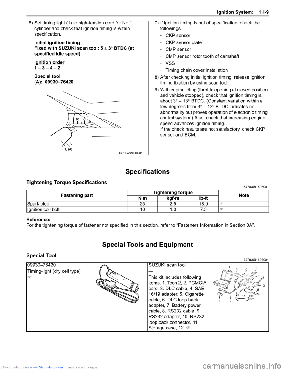
6) Set timing light (1) to high-tension cord for No.1 cylinder and check that ignition timing is within
specification.
Initial ignition timing
Fixed with SUZUKI scan tool: 5 ± 3° BTDC (at
specified idle speed)
Ignition order
1 – 3 – 4 – 2
Special tool
(A): 09930–76420 7) If ignition timing is out
of specification, check the
followings.
• CKP sensor
• CKP sensor plate
• CMP sensor
• CMP sensor rotor tooth of camshaft
• VSS
• Timing chain cover installation
8) After checking initial igniti on timing, release ignition
timing fixation by using scan tool.
9) With engine idling (throttl e opening at closed position
and vehicle stopped), check that ignition timing is
about 3 ° – 13° BTDC. (Constant variation within a
few degrees from 3 ° – 13° BTDC indicates no
abnormality but proves operation of electronic timing
control system.) Also, check that increasing engine
speed advances ignition timing.
If the check results are not satisfactory, check CKP
sensor and ECM.
Specifications
Tightening Torque SpecificationsS7RS0B1807001
Reference:
For the tightening torque of fastener not specified in this section, refer to “Fasteners Information in Section 0A”.
Special Tools and Equipment
Special ToolS7RS0B1808001
1, (A)10
0I3RB0A180004-01
Fastening part Tightening torque
Note
N ⋅mkgf-mlb-ft
Spark plug 25 2.5 18.0 �)
Ignition coil bolt 10 1.0 7.5 �)
09930–76420SUZUKI scan tool
Timing-light (dry cell type) —
�) This kit includes following
items. 1. Tech 2, 2. PCMCIA
card, 3. DLC cable, 4. SAE
16/19 adapter, 5. Cigarette
cable, 6. DLC loop back
adapter, 7. Battery power
cable, 8. RS232 cable, 9.
RS232 adapter, 10. RS232
loop back connector, 11.
Storage case, 12. �)
Page 412 of 1496
Downloaded from www.Manualslib.com manuals search engine 1J-2 Charging System:
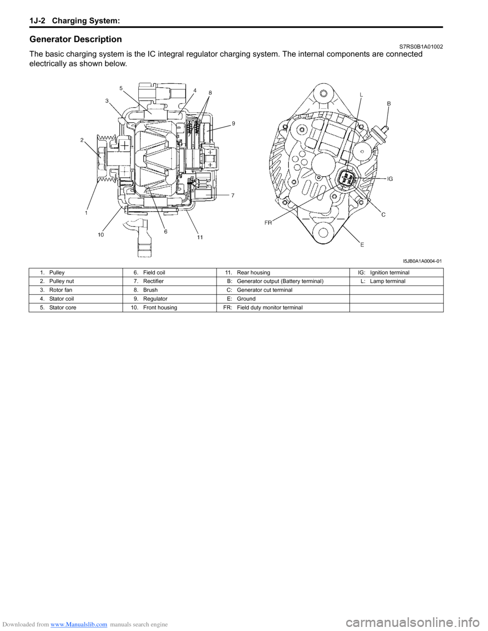
Generator DescriptionS7RS0B1A01002
The basic charging system is the IC integral regulator charging system. The internal co mponents are connected
electrically as shown below.
I5JB0A1A0004-01
1. Pulley 6. Field coil11. Rear housing IG: Ignition terminal
2. Pulley nut 7. RectifierB: Generator output (Battery terminal) L: Lamp terminal
3. Rotor fan 8. BrushC: Generator cut terminal
4. Stator coil 9. RegulatorE: Ground
5. Stator core 10. Front housing FR: Field duty monitor terminal
Page 473 of 1496
Downloaded from www.Manualslib.com manuals search engine Wheels and Tires: 2D-6
Repair Instructions
General Balance ProceduresS7RS0B2406001
Deposits of mud, etc. must be cleaned from inside of rim.
WARNING!
Stones should be removed from the tread in
order to avoid operator injury during spin
balancing and to obtain good balance.
Each tire should be inspected for any damage, then
balanced according to equipment manufacturer’s
recommendation.
Off-Vehicle Balancing
Most electronic off-vehicle balancers are more accurate
than the on-vehicle spin balancers. They are easy to use
and give a dynamic (two plane) balance. Although they
do not correct for drum or disc unbalance as does on-
vehicle spin balancing, this is overcome by their
accuracy, usually to within 1/8 ounce.
On-Vehicle Balancing
On-vehicle balancing methods vary with equipment and
tool manufacturers. Be sure to follow each
manufacturer’s instructions during balancing operation.
WARNING!
Wheel spin should be limited to 55 km/h (35
mph) as indicated on speedometer.
This limit is necessary because speedometer
only indicates one-half of actual wheel speed
when one drive wheel is spinning and the
other drive wheel is stopped.
Unless care is taken in limiting drive wheel
spin, spinning wheel can reach excessive
speeds. This can result in possible tire
disintegration or differential failure, which
could cause serious personal injury or
extensive vehicle damage.
CAUTION!
Using on-vehicle balancing method with
ignition switch ON may set malfunction
diagnostic trouble code (DTC) of ESP® and
ABS even when system is in good condition.
Never turn ignition swit ch ON while spinning
wheel.
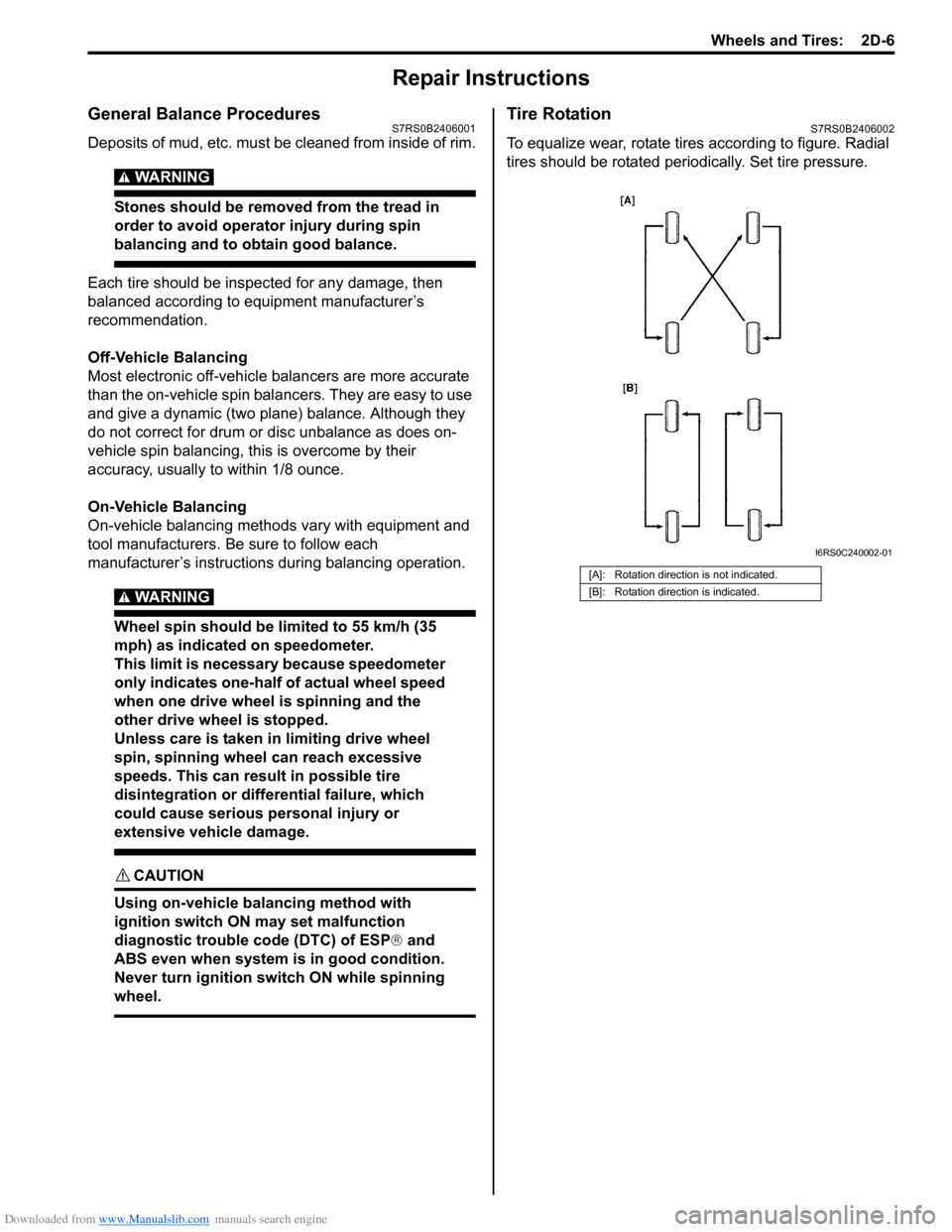
Tire RotationS7RS0B2406002
To equalize wear, rotate tires according to figure. Radial
tires should be rotated periodi cally. Set tire pressure.
[A]: Rotation direction is not indicated.
[B]: Rotation direction is indicated.
I6RS0C240002-01