spec SUZUKI SWIFT 2005 2.G Service Workshop Manual
[x] Cancel search | Manufacturer: SUZUKI, Model Year: 2005, Model line: SWIFT, Model: SUZUKI SWIFT 2005 2.GPages: 1496, PDF Size: 34.44 MB
Page 1133 of 1496
Downloaded from www.Manualslib.com manuals search engine Air Bag System: 8B-95
Inspection of Intermittent and Poor
Connections
S7RS0B8204048
Most intermittents are caused by faulty electrical
connections or wiring. When a check for proper
connection is requested in a diagnostic flow, perform
careful check of suspect circuits.
If any abnormality is found, repair or replace as a wire
harness assembly.
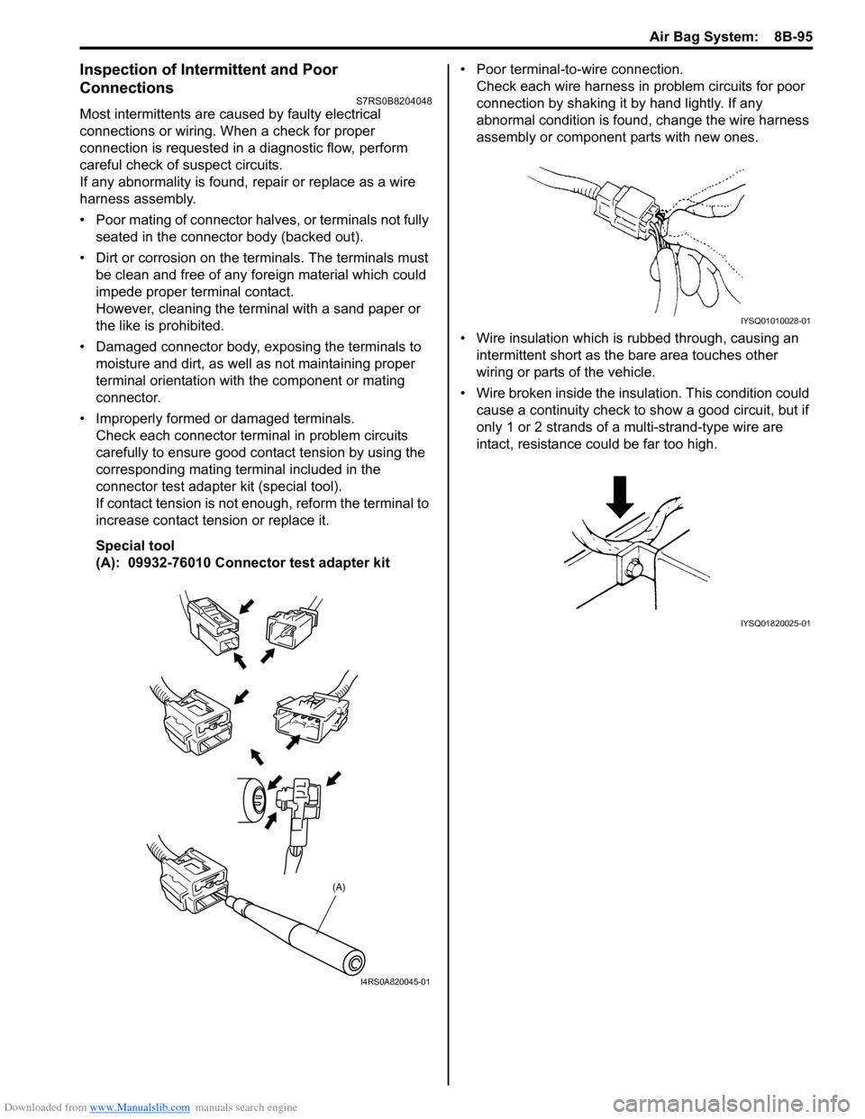
• Poor mating of connector halves, or terminals not fully seated in the connector body (backed out).
• Dirt or corrosion on the terminals. The terminals must be clean and free of any foreign material which could
impede proper terminal contact.
However, cleaning the terminal with a sand paper or
the like is prohibited.
• Damaged connector body, exposing the terminals to moisture and dirt, as well as not maintaining proper
terminal orientation with the component or mating
connector.
• Improperly formed or damaged terminals. Check each connector terminal in problem circuits
carefully to ensure good contact tension by using the
corresponding mating terminal included in the
connector test adapter kit (special tool).
If contact tension is not e nough, reform the terminal to
increase contact tension or replace it.
Special tool
(A): 09932-76010 Connector test adapter kit • Poor terminal-to-wire connection.
Check each wire harness in problem circuits for poor
connection by shaking it by hand lightly. If any
abnormal condition is found, change the wire harness
assembly or component parts with new ones.
• Wire insulation which is rubbed through, causing an intermittent short as the bare area touches other
wiring or parts of the vehicle.
• Wire broken inside the insulation. This condition could cause a continuity check to show a good circuit, but if
only 1 or 2 strands of a multi-strand-type wire are
intact, resistance could be far too high.
(A)
I4RS0A820045-01
IYSQ01010028-01
IYSQ01820025-01
Page 1134 of 1496
Downloaded from www.Manualslib.com manuals search engine 8B-96 Air Bag System:
Repair and Inspection Required after AccidentS7RS0B8204049
CAUTION!
• All air bag system components, including the electrical harness (component
mounting points), must be inspected after
an accident. If any components are
damaged or bent, they must be replaced
even if air bag system activation did not
occur.
• Never use air bag system parts from another vehicle.
• Do not attempt to service the parts below. Service of these parts is by replacement
only.
– Driver / Passenger air bag (inflator) modules
– Driver / Passenger side-air bag (inflator) modules
– Driver / Passenger side curtain-air bag (inflator) modules
– Driver / Passenger seat belt pretensioners
–Forward-sensor
– Driver / Passenger side-sensors
–SDM
– Contact coil and combination switch assembly
– Air bag wire harness in main harness, instrument panel harness and floor
harness.
• Proper operation of the sensors and air bag system requires that any repairs to the
vehicle structure return it to its original
production configuration.
CAUTION!
After detecting one time of such collision as
to meet deployment conditions, the SDM
must not be used.
Refer to “Air Bag Diagnostic System Check”
when checking the SDM.
Accident with Deployment / Activation – Component
Replacement
When driver and passenger air bags are deployed, the
following components must be replaced.
• Driver and passenger air bag (inflator) modules
• Driver and passenger seat belt pretensioners
• SDM after detecting such collision as to meet
deployment conditions
• Forward-sensor
• Instrument panel When side-air bag and side curtain-air bag are deployed,
the following components must be replaced.
• Deployed side-air bag (inflator) module
• Deployed side curtain-air bag (inflator) module
• Side-sensor
•SDM
Accident with or without Deployment / Activation –
Component Inspections
Certain air bag and restraint system components must
be inspected after any crash, whether the air bag system
activated or not. If any faul
ty condition is found in the
following checks, replace faulty part.
Those components are:
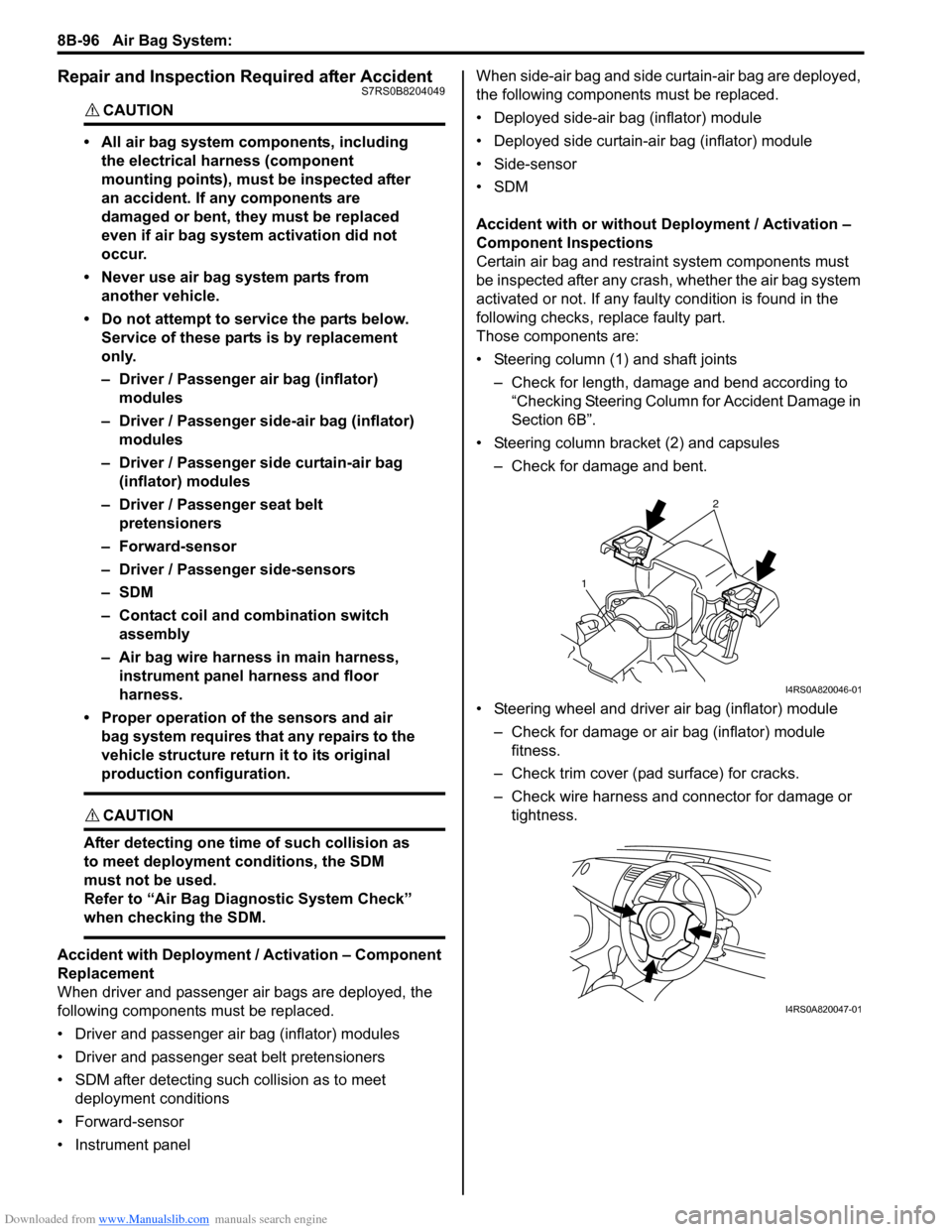
• Steering column (1) and shaft joints
– Check for length, damage and bend according to “Checking Steering Column for Accident Damage in
Section 6B”.
• Steering column bracket (2) and capsules – Check for damage and bent.
• Steering wheel and driver air bag (inflator) module – Check for damage or air bag (inflator) module fitness.
– Check trim cover (pad surface) for cracks.
– Check wire harness and connector for damage or tightness.
2
1
I4RS0A820046-01
I4RS0A820047-01
Page 1135 of 1496
Downloaded from www.Manualslib.com manuals search engine Air Bag System: 8B-97
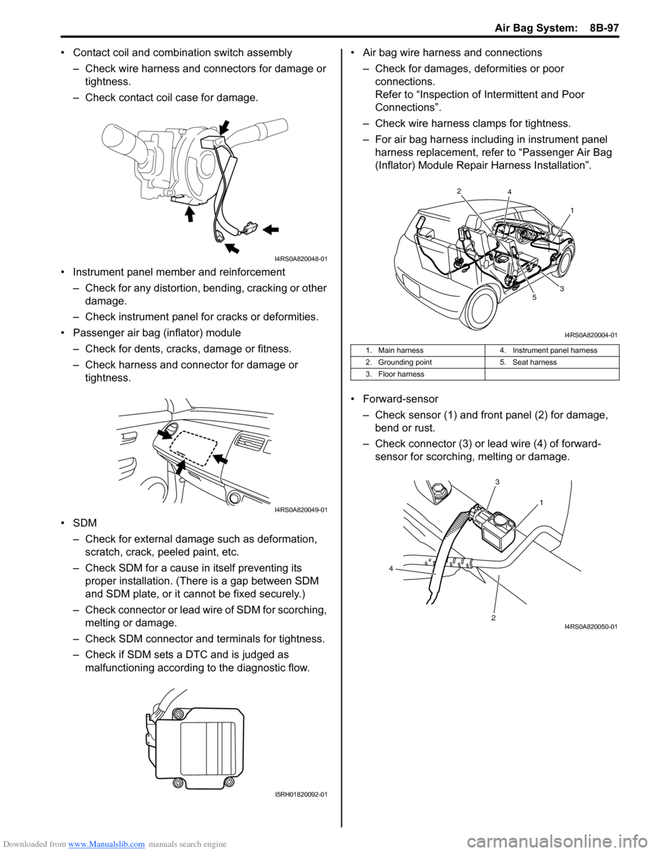
• Contact coil and combination switch assembly
– Check wire harness and connectors for damage or tightness.
– Check contact coil case for damage.
• Instrument panel member and reinforcement – Check for any distortion, bending, cracking or other damage.
– Check instrument panel fo r cracks or deformities.
• Passenger air bag (inflator) module
– Check for dents, cracks, damage or fitness.
– Check harness and connector for damage or tightness.
•SDM – Check for external damage such as deformation, scratch, crack, peeled paint, etc.
– Check SDM for a cause in itself preventing its proper installation. (There is a gap between SDM
and SDM plate, or it cannot be fixed securely.)
– Check connector or lead wire of SDM for scorching, melting or damage.
– Check SDM connector and terminals for tightness.
– Check if SDM sets a DTC and is judged as malfunctioning according to the diagnostic flow. • Air bag wire harness and connections
– Check for damages, deformities or poor connections.
Refer to “Inspection of Intermittent and Poor
Connections”.
– Check wire harness clamps for tightness.
– For air bag harness including in instrument panel harness replacement, refer to “Passenger Air Bag
(Inflator) Module Repair Harness Installation”.
• Forward-sensor – Check sensor (1) and front panel (2) for damage, bend or rust.
– Check connector (3) or lead wire (4) of forward- sensor for scorching, melting or damage.
I4RS0A820048-01
I4RS0A820049-01
I5RH01820092-01
1. Main harness 4. Instrument panel harness
2. Grounding point 5. Seat harness
3. Floor harness
1
2
3
4
5
I4RS0A820004-01
1
3
2
4
I4RS0A820050-01
Page 1139 of 1496
Downloaded from www.Manualslib.com manuals search engine Air Bag System: 8B-101
Installation1) Check that none of the following faulty conditions exists.
• Bend, scratch, deformity in vehicle body where SDM is mounted.
• Foreign matter or rust on mating surface of vehicle body where SDM is mounted.
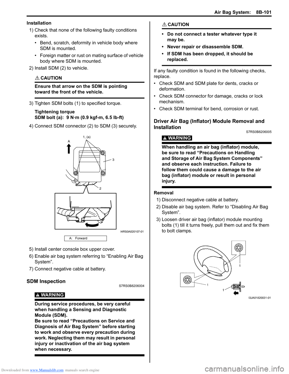
2) Install SDM (2) to vehicle.
CAUTION!
Ensure that arrow on the SDM is pointing
toward the front of the vehicle.
3) Tighten SDM bolts (1) to specified torque.
Tightening torque
SDM bolt (a): 9 N·m (0.9 kgf-m, 6.5 lb-ft)
4) Connect SDM connector (2) to SDM (3) securely.
5) Install center console box upper cover.
6) Enable air bag system referring to “Enabling Air Bag System”.
7) Connect negative cable at battery.
SDM InspectionS7RS0B8206004
WARNING!
During service procedures, be very careful
when handling a Sensing and Diagnostic
Module (SDM).
Be sure to read “Precautions on Service and
Diagnosis of Air Bag System” before starting
to work and observe every precaution during
work. Neglecting them ma y result in personal
injury or inactivation of the air bag system
when necessary.
CAUTION!
• Do not connect a tester whatever type it may be.
• Never repair or disassemble SDM.
• If SDM has been dropped, it should be replaced.
If any faulty condition is fo und in the following checks,
replace.
• Check SDM and SDM plate for dents, cracks or deformation.
• Check SDM connector for damage, cracks or lock mechanism.
• Check SDM terminal for bend, corrosion or rust.
Driver Air Bag (Inflator) Module Removal and
Installation
S7RS0B8206005
WARNING!
When handling an air bag (inflator) module,
be sure to read “Precautions on Handling
and Storage of Air Bag System Components”
and observe each instruction. Failure to
follow them could cause a damage to the air
bag (inflator) module or result in personal
injury.
Removal 1) Disconnect negative cable at battery.
2) Disable air bag system. Re fer to “Disabling Air Bag
System”.
3) Loosen driver air bag (inflator) module mounting bolts (1) till it turns freely, pull them out and fix them
to bolt clamps.
A: Forward
2 3
A
1, (a)
I4RS0A820107-01
I3JA01820031-01
Page 1140 of 1496
Downloaded from www.Manualslib.com manuals search engine 8B-102 Air Bag System:
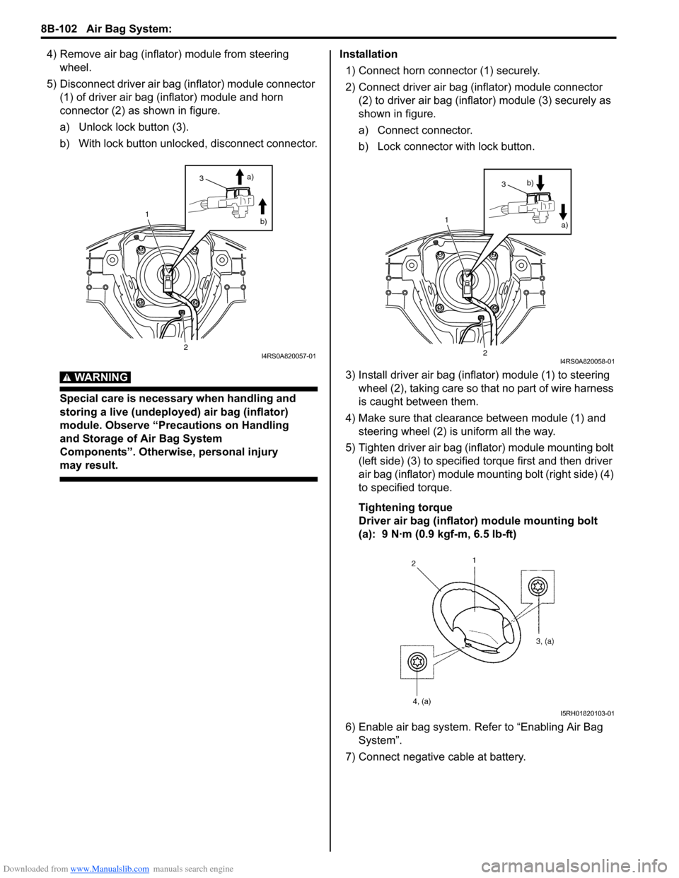
4) Remove air bag (inflator) module from steering wheel.
5) Disconnect driver air bag (inflator) module connector (1) of driver air bag (inflator) module and horn
connector (2) as shown in figure.
a) Unlock lock button (3).
b) With lock button unlocked, disconnect connector.
WARNING!
Special care is necessary when handling and
storing a live (undeployed) air bag (inflator)
module. Observe “Precautions on Handling
and Storage of Air Bag System
Components”. Otherwise, personal injury
may result.
Installation
1) Connect horn connector (1) securely.
2) Connect driver air bag (inflator) module connector (2) to driver air bag (inflator) module (3) securely as
shown in figure.
a) Connect connector.
b) Lock connector with lock button.
3) Install driver air bag (inflator) module (1) to steering wheel (2), taking care so t hat no part of wire harness
is caught between them.
4) Make sure that clearance between module (1) and steering wheel (2) is uniform all the way.
5) Tighten driver air bag (inflator) module mounting bolt (left side) (3) to specified torque first and then driver
air bag (inflator) module mounting bolt (right side) (4)
to specified torque.
Tightening torque
Driver air bag (inflator) module mounting bolt
(a): 9 N·m (0.9 kgf-m, 6.5 lb-ft)
6) Enable air bag system. Refer to “Enabling Air Bag System”.
7) Connect negative cable at battery.
1
2
3 a)
b)
I4RS0A820057-01
1
2
3 a)
b)
I4RS0A820058-01
I5RH01820103-01
Page 1141 of 1496
Downloaded from www.Manualslib.com manuals search engine Air Bag System: 8B-103
Driver Air Bag (Inflator) Module InspectionS7RS0B8206006
WARNING!
Never disassemble air bag (inflator) module
or measure its resistance. Otherwise,
personal injury may result.
CAUTION!
If air bag (inflator) module was dropped from
a height of 90 cm (3 ft) or more, it should be
replaced.
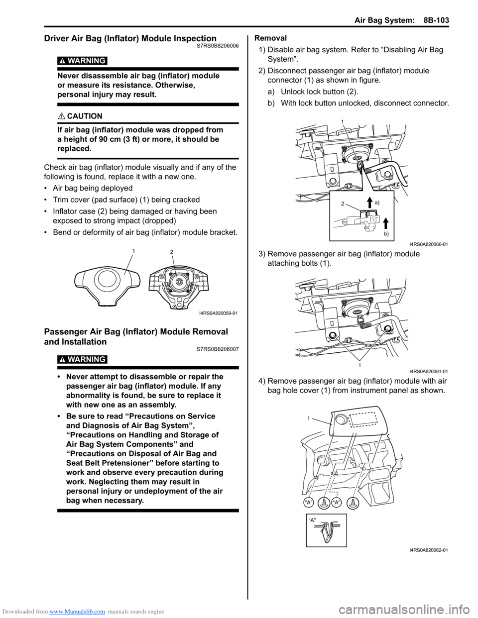
Check air bag (inflator) module visually and if any of the
following is found, replace it with a new one.
• Air bag being deployed
• Trim cover (pad surface) (1) being cracked
• Inflator case (2) being damaged or having been exposed to strong impact (dropped)
• Bend or deformity of air bag (inflator) module bracket.
Passenger Air Bag (Inflator) Module Removal
and Installation
S7RS0B8206007
WARNING!
• Never attempt to disassemble or repair the passenger air bag (inflator) module. If any
abnormality is found, be sure to replace it
with new one as an assembly.
• Be sure to read “Precautions on Service and Diagnosis of Air Bag System”,
“Precautions on Handling and Storage of
Air Bag System Components” and
“Precautions on Disposal of Air Bag and
Seat Belt Pretensioner” before starting to
work and observe every precaution during
work. Neglecting them may result in
personal injury or undeployment of the air
bag when necessary.
Removal
1) Disable air bag system. Re fer to “Disabling Air Bag
System”.
2) Disconnect passenger air bag (inflator) module connector (1) as shown in figure.
a) Unlock lock button (2).
b) With lock button unlocked, disconnect connector.
3) Remove passenger air bag (inflator) module attaching bolts (1).
4) Remove passenger air bag (inflator) module with air bag hole cover (1) from instrument panel as shown.
1 2
I4RS0A820059-01
2
1
a)b)
I4RS0A820060-01
1I4RS0A820061-01
“A”
“A”“A”
1
I4RS0A820062-01
Page 1143 of 1496
Downloaded from www.Manualslib.com manuals search engine Air Bag System: 8B-105
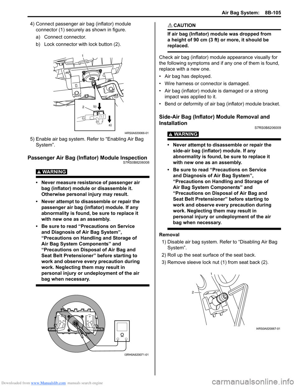
4) Connect passenger air bag (inflator) module connector (1) securely as shown in figure.
a) Connect connector.
b) Lock connector with lock button (2).
5) Enable air bag system. Refer to “Enabling Air Bag System”.
Passenger Air Bag (Inflator) Module InspectionS7RS0B8206008
WARNING!
• Never measure resistance of passenger air bag (inflator) module or disassemble it.
Otherwise personal injury may result.
• Never attempt to disassemble or repair the passenger air bag (inflator) module. If any
abnormality is found, be sure to replace it
with new one as an assembly.
• Be sure to read “Precautions on Service and Diagnosis of Air Bag System”,
“Precautions on Handling and Storage of
Air Bag System Components” and
“Precautions on Disposal of Air Bag and
Seat Belt Pretensioner” before starting to
work and observe every precaution during
work. Neglecting them may result in
personal injury or undeployment of the air
bag when necessary.
CAUTION!
If air bag (Inflator) module was dropped from
a height of 90 cm (3 ft) or more, it should be
replaced.
Check air bag (inflator) module appearance visually for
the following symptoms and if any one of them is found,
replace with a new one.
• Air bag has deployed.
• Wire harness or connector is damaged.
• Air bag (inflator) module is damaged or a strong impact was applied to it.
• Bend or deformity of air bag (inflator) module bracket.
Side-Air Bag (Inflator) Module Removal and
Installation
S7RS0B8206009
WARNING!
• Never attempt to disassemble or repair the side-air bag (inflator) module. If any
abnormality is found, be sure to replace it
with new one as an assembly.
• Be sure to read “Precautions on Service and Diagnosis of Air Bag System”,
“Precautions on Handling and Storage of
Air Bag System Components” and
“Precautions on Disposal of Air Bag and
Seat Belt Pretensioner” before starting to
work and observe every precaution during
work. Neglecting them may result in
personal injury or undeployment of the air
bag when necessary.
Removal
1) Disable air bag system. Re fer to “Disabling Air Bag
System”.
2) Roll up the seat surface of the seat back.
3) Remove sleeve lock nut (1) from seat back (2).
1
2
a)
b)
I4RS0A820066-01
I3RH0A820071-01
1
2
I4RS0A820067-01
Page 1144 of 1496
Downloaded from www.Manualslib.com manuals search engine 8B-106 Air Bag System:
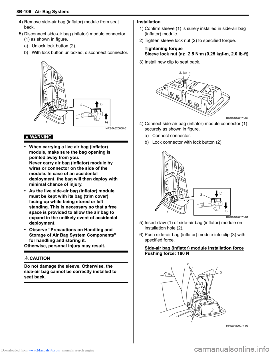
4) Remove side-air bag (inflator) module from seat back.
5) Disconnect side-air bag (inflator) module connector (1) as shown in figure.
a) Unlock lock button (2).
b) With lock button unlocked, disconnect connector.
WARNING!
• When carrying a live air bag (inflator) module, make sure the bag opening is
pointed away from you.
Never carry air bag (inflator) module by
wires or connector on the side of the
module. In case of an accidental
deployment, the bag will then deploy with
minimal chance of injury.
• As the live side-air bag (inflator) module must be kept with its bag (trim cover)
facing up while being stored or left
standing. This is necessary so that a free
space is provided to allow the air bag to
expand in the unlikely event of accidental
deployment.
• Observe “Precautions on Handling and Storage of Air Bag System Components”
for handling and storing it.
Otherwise, personal injury may result.
CAUTION!
Do not damage the sleeve. Otherwise, the
side-air bag cannot be correctly installed to
seat back.
Installation
1) Confirm sleeve (1) is surely installed in side-air bag (inflator) module.
2) Tighten sleeve lock nut (2) to specified torque.
Tightening torque
Sleeve lock nut (a): 2.5 N·m (0.25 kgf-m, 2.0 lb-ft)
3) Install new clip to seat back.
4) Connect side-air bag (inflator) module connector (1) securely as shown in figure.
a) Connect connector.
b) Lock connector wi th lock button (2).
5) Insert claw (1) of side-air bag (inflator) module on installation hole (2).
6) Push side-air bag (inflator) module into clip (3) with
specified force.
Side-air bag (inflator) module installation force
Pushing force: 180 N
2
1
a)
b)
I4RS0A820068-01
12, (a)
I4RS0A820073-02
1
2 a)
b)
I4RS0A820070-01
1
2
3
I4RS0A820074-02
Page 1145 of 1496
Downloaded from www.Manualslib.com manuals search engine Air Bag System: 8B-107
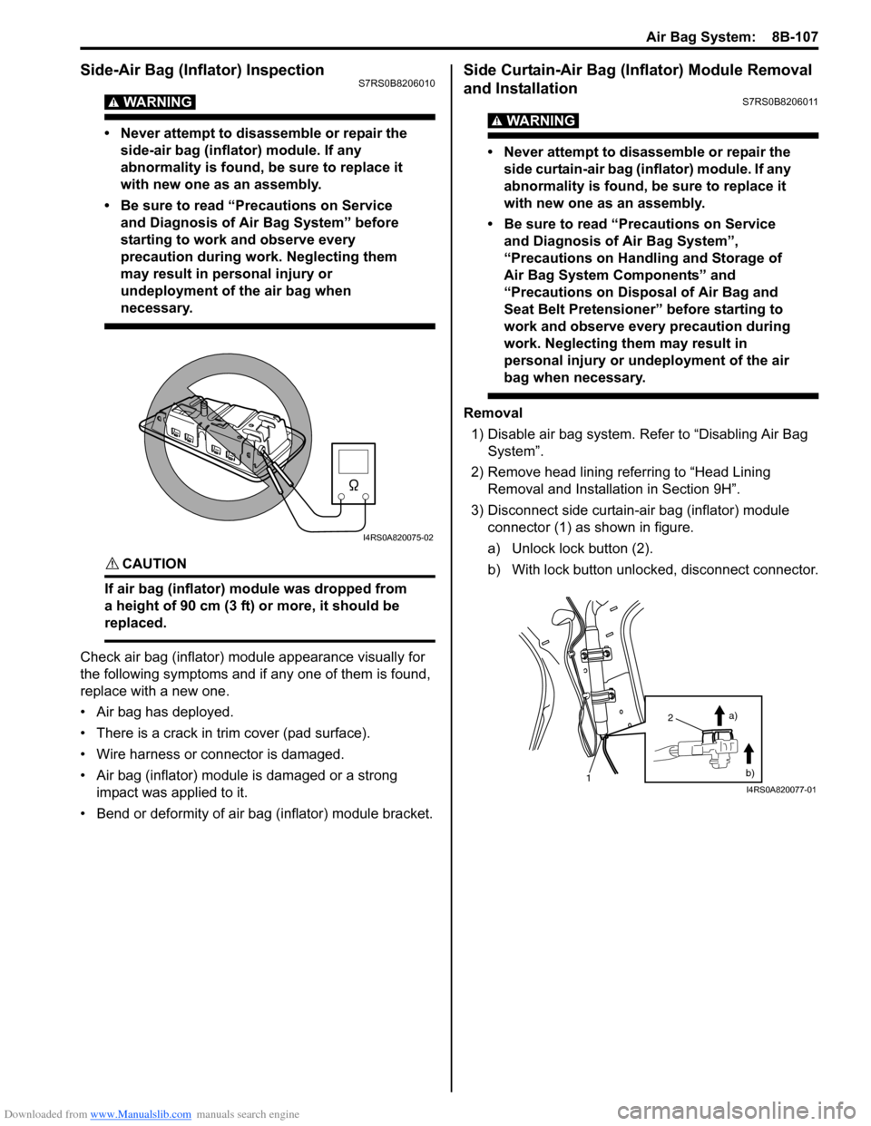
Side-Air Bag (Inflator) InspectionS7RS0B8206010
WARNING!
• Never attempt to disassemble or repair the side-air bag (inflator) module. If any
abnormality is found, be sure to replace it
with new one as an assembly.
• Be sure to read “Precautions on Service and Diagnosis of Air Bag System” before
starting to work and observe every
precaution during work. Neglecting them
may result in personal injury or
undeployment of the air bag when
necessary.
CAUTION!
If air bag (inflator) module was dropped from
a height of 90 cm (3 ft) or more, it should be
replaced.
Check air bag (inflator) module appearance visually for
the following symptoms and if any one of them is found,
replace with a new one.
• Air bag has deployed.
• There is a crack in trim cover (pad surface).
• Wire harness or connector is damaged.
• Air bag (inflator) module is damaged or a strong impact was applied to it.
• Bend or deformity of air bag (inflator) module bracket.
Side Curtain-Air Bag (Inflator) Module Removal
and Installation
S7RS0B8206011
WARNING!
• Never attempt to disassemble or repair the side curtain-air bag (inflator) module. If any
abnormality is found, be sure to replace it
with new one as an assembly.
• Be sure to read “Precautions on Service and Diagnosis of Air Bag System”,
“Precautions on Handling and Storage of
Air Bag System Components” and
“Precautions on Disposal of Air Bag and
Seat Belt Pretensioner” before starting to
work and observe every precaution during
work. Neglecting them may result in
personal injury or undeployment of the air
bag when necessary.
Removal
1) Disable air bag system. Re fer to “Disabling Air Bag
System”.
2) Remove head lining referring to “Head Lining Removal and Installati on in Section 9H”.
3) Disconnect side curtain-air bag (inflator) module connector (1) as shown in figure.
a) Unlock lock button (2).
b) With lock button unlocked, disconnect connector.
I4RS0A820075-02
2
1 a)
b)
I4RS0A820077-01
Page 1146 of 1496

Downloaded from www.Manualslib.com manuals search engine 8B-108 Air Bag System:
4) Remove side curtain-air bag (inflator) module fixing bolts (1) and clips (2).
5) Remove side curtain-air bag (inflator) module.
WARNING!
• When carrying a live air bag (inflator) module, make sure the bag opening is
pointed away from you.
Never carry air bag (inflator) module by
wires or connector on the side of the
module. In case of an accidental
deployment, the bag will then deploy with
minimal chance of injury.
• As the live curtain air bag (inflator) module must be kept with it s bag facing up while
being stored or left standing. This is
necessary so that a free space is provided
to allow the air bag to expand in the
unlikely event of accidental deployment.
• Observe “Precautions on Handling and Storage of Air Bag System Components”
for handling and storing it.
Otherwise, personal injury may result.
Installation
WARNING!
Do not install side curtain-air bag (inflator)
module while twisted or bended. Otherwise,
side curtain-air bag (inflator) module may not
deploy and injury may result.
1) Install side curtain-air bag (inflator) module (1) with
clips and new bolts.
2) Tighten side curtain-air bag (inflator) module attaching bolts (1) to specified torque.
Tightening torque
Side curtain-air bag (inflator) module attaching
bolts (a): 11 N·m (1.1 kgf-m, 8.0 lb-ft)
3) Connect side curtain-air bag (inflator) module connector (1) securely as shown in figure.
a) Connect connector.
b) Lock connector wi th lock button (2).
4) Install head lining referring to “Head Lining Removal and Installation in Section 9H”.
5) Enable air bag system. Refer to “Enabling Air Bag System”.1 2
2
22
1
I4RS0A820076-01
1,(a) 1,(a)
I4RS0A820110-01
1
2
a)
b)
I4RS0A820055-01