1k-4 SUZUKI SWIFT 2005 2.G Service Workshop Manual
[x] Cancel search | Manufacturer: SUZUKI, Model Year: 2005, Model line: SWIFT, Model: SUZUKI SWIFT 2005 2.GPages: 1496, PDF Size: 34.44 MB
Page 49 of 1496

Downloaded from www.Manualslib.com manuals search engine Table of Contents 1-v
Ignition Timing Inspection ................................... 1H-8
Specifications ....................................................... 1H-9
Tightening Torque Specifications ........................ 1H-9
Special Tools and Equipmen t ............................. 1H-9
Special Tool ........................................................ 1H-9
Starting System ................. ........................ 1I-1
Schematic and Routing Diagram ......................... 1I-1
Cranking System Circuit Diagram ........................ 1I-1
Diagnostic Information and Procedures ............. 1I-1
Cranking System Symptom Diagnosis ................. 1I-1
Cranking System Test.......................................... 1I-3
Repair Instructions ............................................... 1I-4 Starting Motor Dismounting and Remounting ...... 1I-4
Starting Motor Components ................................. 1I-5
Starting Motor Inspection ..................................... 1I-6
Specifications ........................................................ 1I-9
Cranking System Specifications........................... 1I-9
Tightening Torque Specifications ......................... 1I-9
Special Tools and Equipment .............................. 1I-9
Recommended Service Material .......................... 1I-9
Charging System ............ .......................... 1J-1
General Description ......... .................................... 1J-1
Battery Description ...............................................1J-1
Generator Descripti on ..........................................1J-2
Diagnostic Information and Procedures ............ 1J-4 Battery Inspection ................................................1J-4
Generator Symptom Diagnosis ............................1J-4 Generator Test (Undercharged Battery
Check) ............................................................... 1J-5
Generator Test (Overcharg ed Battery Check) .... 1J-6
Repair Instructions ........... ................................... 1J-6
Jump Starting in Case of Emergency.................. 1J-6
Battery Dismounting and Remounting ................ 1J-7
Water Pump / Generator Drive Belt Tension Inspection and Adjustment ................................ 1J-7
Water Pump / Generator Drive Belt Removal and Installation .................................................. 1J-8
Generator Unit Co mponents ............................... 1J-9
Generator Dismounting a nd Remounting............ 1J-9
Generator Components........ ............................. 1J-10
Generator Insp ection......................................... 1J-11
Specifications ..................................................... 1J-13 Charging System Specifications ....................... 1J-13
Tightening Torque Specifications ...................... 1J-13
Exhaust System .............. ......................... 1K-1
General Description .............................................1K-1
Exhaust System Description ............................... 1K-1
Diagnostic Information and Procedures ............1K-1 Exhaust System Check ....................................... 1K-1
Repair Instructions ........... ...................................1K-2
Exhaust System Components ............................. 1K-2
Exhaust Manifold Removal and Installation ........ 1K-3
Exhaust Pipe and Muffler Removal and Installation ......................................................... 1K-4
Specifications .................... ...................................1K-5
Tightening Torque Specifications ........................ 1K-5
Page 427 of 1496

Downloaded from www.Manualslib.com manuals search engine Exhaust System: 1K-4
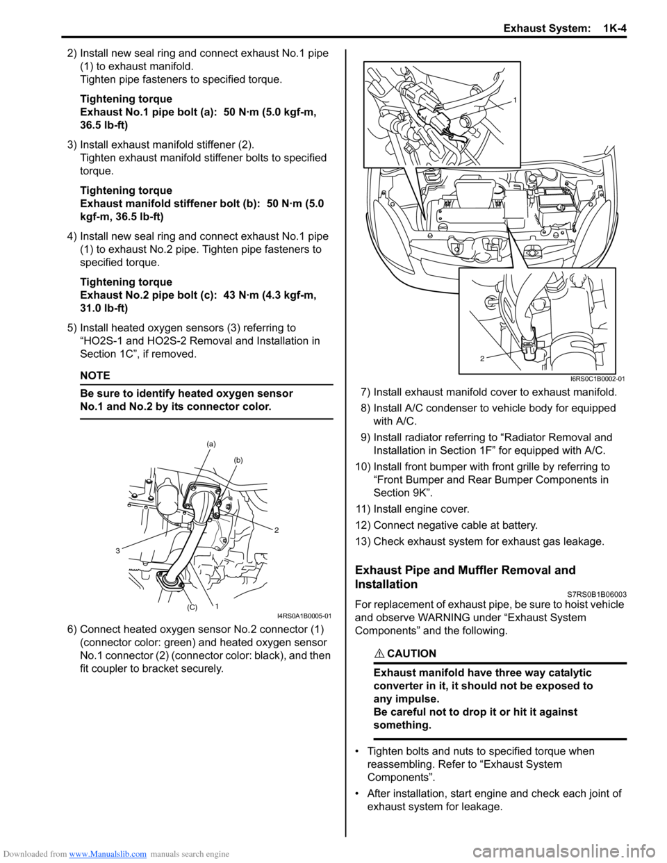
2) Install new seal ring and connect exhaust No.1 pipe (1) to exhaust manifold.
Tighten pipe fasteners to specified torque.
Tightening torque
Exhaust No.1 pipe bolt (a): 50 N·m (5.0 kgf-m,
36.5 lb-ft)
3) Install exhaust manifold stiffener (2). Tighten exhaust manifold stiffener bolts to specified
torque.
Tightening torque
Exhaust manifold stiffener bolt (b): 50 N·m (5.0
kgf-m, 36.5 lb-ft)
4) Install new seal ring and connect exhaust No.1 pipe (1) to exhaust No.2 pipe. Tighten pipe fasteners to
specified torque.
Tightening torque
Exhaust No.2 pipe bolt (c): 43 N·m (4.3 kgf-m,
31.0 lb-ft)
5) Install heated oxygen sensors (3) referring to “HO2S-1 and HO2S-2 Removal and Installation in
Section 1C”, if removed.
NOTE
Be sure to identify heated oxygen sensor
No.1 and No.2 by its connector color.
6) Connect heated oxygen sensor No.2 connector (1)
(connector color: green) and heated oxygen sensor
No.1 connector (2) (connector color: black), and then
fit coupler to br acket securely. 7) Install exhaust manifold cover to exhaust manifold.
8) Install A/C condenser to vehicle body for equipped
with A/C.
9) Install radiator referrin g to “Radiator Removal and
Installation in Section 1F” for equipped with A/C.
10) Install front bumper with fr ont grille by referring to
“Front Bumper and Rear Bumper Components in
Section 9K”.
11) Install engine cover.
12) Connect negative cable at battery.
13) Check exhaust system for exhaust gas leakage.
Exhaust Pipe and Muffler Removal and
Installation
S7RS0B1B06003
For replacement of exhaust pipe, be sure to hoist vehicle
and observe WARNING under “Exhaust System
Components” and the following.
CAUTION!
Exhaust manifold have three way catalytic
converter in it, it should not be exposed to
any impulse.
Be careful not to drop it or hit it against
something.
• Tighten bolts and nuts to specified torque when reassembling. Refer to “Exhaust System
Components”.
• After installation, start engine and check each joint of exhaust system for leakage.
2
(b)
(a)
1(C)
3
I4RS0A1B0005-01
1
2
I6RS0C1B0002-01