G37 SUZUKI SWIFT 2006 2.G Service Owner's Guide
[x] Cancel search | Manufacturer: SUZUKI, Model Year: 2006, Model line: SWIFT, Model: SUZUKI SWIFT 2006 2.GPages: 1496, PDF Size: 34.44 MB
Page 1267 of 1496
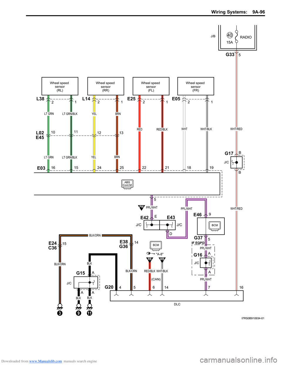
Downloaded from www.Manualslib.com manuals search engine Wiring Systems: 9A-96
YEL
ABS
Cont.M
L38
LT GRN/BLKLT GRN
LT GRN/BLKLT GRN
L02
E451011
Wheel speed
sensor(RL)
BRN
YELBRN
13
12
L14
Wheel speed
sensor(RR)
WHT/BLK
E05
Wheel speed sensor(FR)
WHTRED
E25
Wheel speed sensor(FL)
RED/BLK
E03
2 12 12 121
5
DLC
PPL/WHT
PPL/WHT
A
A
E38
G36
5
E42
D
J/C
G16
PPL/WHT
E
59E46
BCM
BCMPPL/WHT
WHT/RED
G20 G37
PW
WHT/BLKRED/BLK
RBWB
"A-8"
11
BLK
BLK
A
A
J/C
G15
4
E24
C3615
BLK/ORN
3
BLK/ORN
9
BLK
A
B
B
J/C
G17
15A RADIO
40
G335
WHT/RED
J/B
BLK/ORN
14
6
716
14
E43
J/C
J/C
(CAN) IF EQPD
16
15 24 25 22 21 18 19
I7RS0B910934-01
Page 1268 of 1496
Downloaded from www.Manualslib.com manuals search engine 9A-97 Wiring Systems:
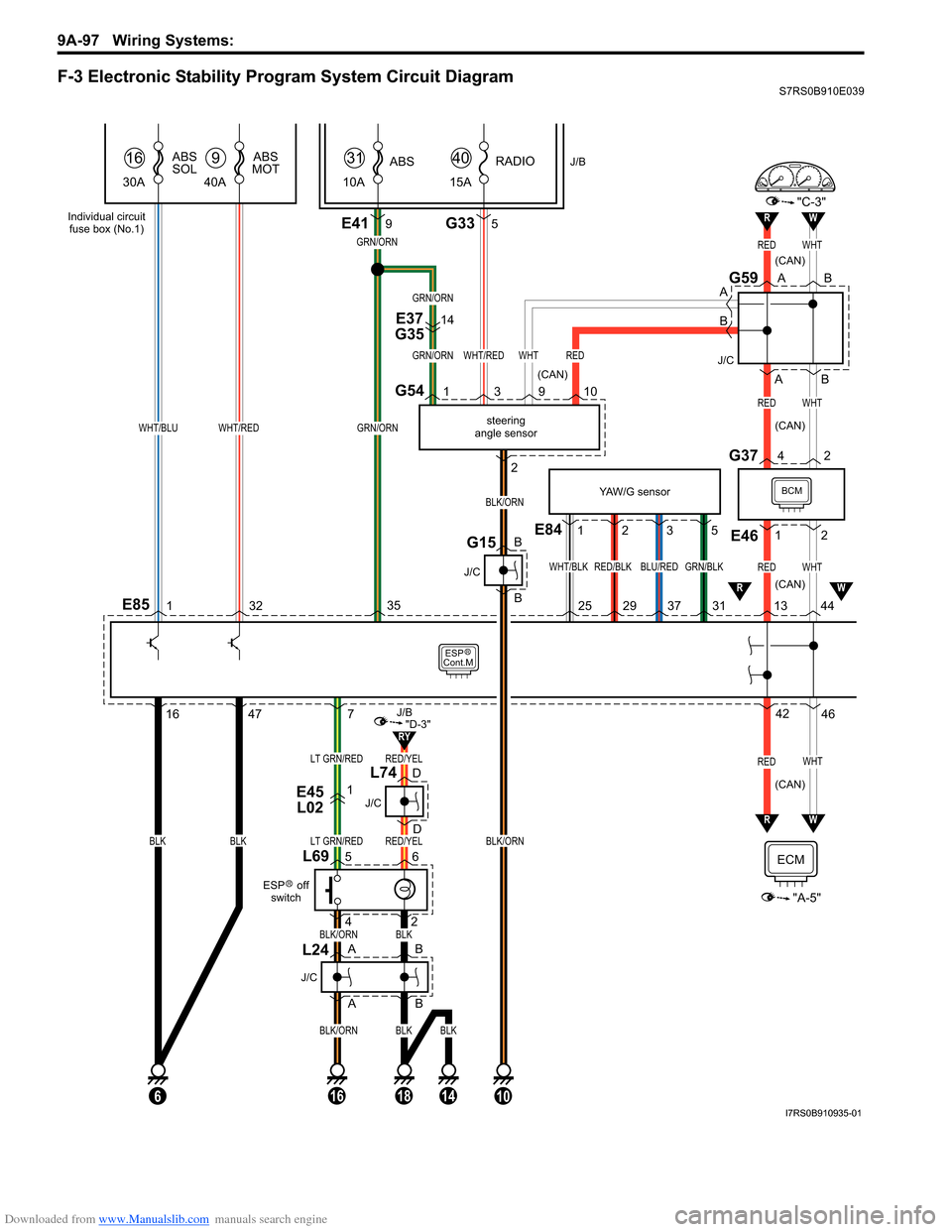
F-3 Electronic Stability Program System Circuit DiagramS7RS0B910E039
1647
132 13
44E85
BLK
ABS
SOLABS
MOT
WHT/REDWHT/BLU
6
BLK
REDWHT
REDWHT
REDWHT
25
BLK/ORN
GRN/ORN
GRN/ORN
GRN/ORN
Individual circuit
fuse box (No.1) J/B
ABS
GRN/ORN
ECM
35
"A-5"
"C-3"
steering
angle sensor
RED
R
4246
WHT
W
RW
1
4G37
E46
2
2
BCM
A
A
A
BG59
B
B
RW
2
1
WHT/REDWHTRED
3910
(CAN) (CAN)
(CAN)
(CAN)
(CAN)
7
ESP
Cont.M
1E45 L02
LT GRN/RED
LT GRN/REDRED/YEL
RED/YEL
BLK/ORN
WHT/BLK
RY
J/C J/C
B
BLKBLK
BLK/ORN
BLK/ORN
16181410
BLK
ESP off
switch
L6956
42
G15
G541
29
RED/BLK
2
37
BLU/RED
3
31
GRN/BLK
5E84B
J/C
D
L74D
R
R
"D-3"J/B
YAW/G sensor
J/C
A
L24A
B
B
30A
16
40A
9
10A
31
15A
RADIO
40
E419G335
E37
G3514
I7RS0B910935-01
Page 1269 of 1496
Downloaded from www.Manualslib.com manuals search engine Wiring Systems: 9A-98
YEL
ESP
Cont.M
L38
LT GRN/BLKLT GRN
LT GRN/BLKLT GRN
L02
E4510
5 6 12 11 14 15 3 211
Wheel speed sensor(RL)
BRN
YELBRN
13
12
L14
Wheel speed
sensor(RR)
WHT/BLK
E05
Wheel speed sensor(FR)
WHTRED
E25
Wheel speed sensor(FL)
RED/BLK
E85
2 12 12 121
33
DLC
PPL/WHT
PPL/WHT
A
A
E38
G36
5
E42
D
J/C
G16
PPL/WHT
E
59E46
BCM
BCMPPL/WHT
WHT/RED
G20 G37
PW
WHT/BLKRED/BLK
RBWB
"A-8"
11
BLK
BLK
A
A
J/C
G15
4
E24
C3615
BLK/ORN
3
BLK/ORN
9
BLK
A
B
B
J/C
G17
15A RADIO
40
G335
WHT/RED
J/B
BLK/ORN
14
6
716
14
E43
J/C
J/C
(CAN) IF EQPD
R
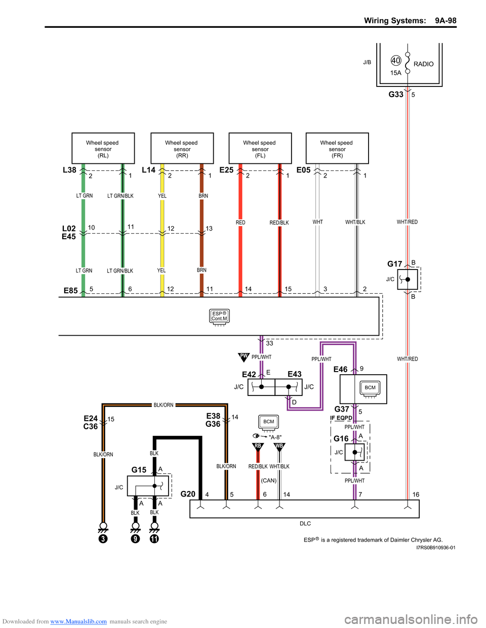
RESP is a registered trademark of Daimler Chrysler AG.I7RS0B910936-01
Page 1271 of 1496
Downloaded from www.Manualslib.com manuals search engine Wiring Systems: 9A-100
B
P/S
Cont.M
6
J/C
E42
E48
E50
E
D
G35 E37
J/C
E43
E54
M
REDBLK
E51
ECM
"A-5"
GRYBRN
1211
125
GRY
BRN
1 4
E52
PPL
2
P
4
PPL/WHT
PPL/WHT
EPS
METER
10A25
G2831
G336
RED/BLK
25PPL
G20
DLC
4
BLK
A
A
J/C
G15
5
PPL/WHT
PPL/WHT
A
A
J/C
G16
9E46
E38
G3614
E24
C3615
BLK/ORN
5
3
J/B
15A RADIO
40
G335
WHT/RED
BLK/ORN
16
7
B
B
J/C
G17
BLK/ORN
11
BCM
WHT/RED
G37
9
BLK
A
BLK
PW
WHT/BLKRED/BLK
RBWB
"A-8"
14
6
GRY
1
G
BCM
PPL/WHT
RHD
LHDAB
AB1
2AB2
1
(CAN)
IF EQPD
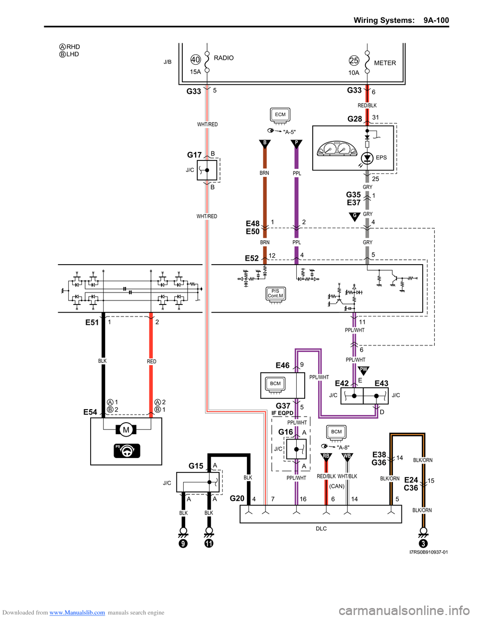
I7RS0B910937-01
Page 1273 of 1496
Downloaded from www.Manualslib.com manuals search engine Wiring Systems: 9A-102
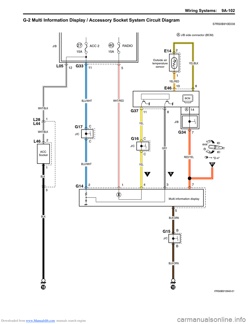
G-2 Multi Information Display / Accessory Socket System Circuit DiagramS7RS0B910E038
11
BLU/WHT
BLU/WHT
15AACC 2
27
J/C
G17
L28
L44
YG
Multi information display
J/B
BCM
J/B
G34
7
14
RED/YEL
10
BLK/ORN
2
BLK/ORN
15A RADIO
40
G335
WHT/RED
G141
3
J/C
YEL
YEL
G16
4
57
G15
J/C
12L05
WHT/BLK
L46
ACC
Socket
2
1
18
WHT/BLK
BLK
BLK
3 1
C
C
B
B
C
C
GRY
G378
11
"D-4"
RY
YEL/RED
YEL/BLK
2E14
1
8
10E46
A
J/B side connector (BCM)
A
Outside air
temperature sensor
I7RS0B910948-01
Page 1278 of 1496
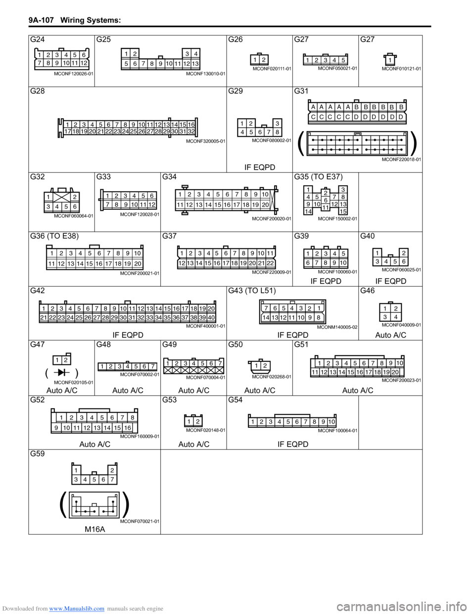
Downloaded from www.Manualslib.com manuals search engine 9A-107 Wiring Systems:
G24G25 G26G27 G27
G28 G29G31
IF EQPD
G32 G33G34 G35 (TO E37)
G36 (TO E38) G37G39G40
IF EQPD IF EQPD
G42 G43 (TO L51)G46
IF EQPD IF EQPDAuto A/C
G47 G48G49G50G51
Auto A/C Auto A/C Auto A/C Auto A/C Auto A/C
G52 G53G54
Auto A/C Auto A/CIF EQPD
G59
M16A
21
83
9 4
10 5
11 6
12
7
MCONF120026-01
710
56 12 34
8 9 11 12 13
MCONF130010-01
21
MCONF020111-01
12345MCONF050021-011
MCONF010121-01
1
17 2
18 3
19 4
20 5
21 6
22 7
23 8
24 9
25 10
26 11
27 12
28 13
29 14
30 15
31 16
32
MCONF320005-01
12 3
8
467 5
MCONF080002-01
AA A A A
BBBB
BB
CCC C CD DD D DD
()
MCONF220018-01
6543 21
MCONF060064-01
12345
78 11 6
12
910
MCONF120028-01
10
11 12 13 14 15 16 17 18 19 123456789
20
MCONF200020-01
14951071214
381315
2611
MCONF150002-01
10
11 12 13 14 15 16 17 18 19 123456789
20
MCONF200021-01
1234567891011
12 13 14 15 16 17 18 19 20 21 22
MCONF220009-01
54321
109876
MCONF100060-01
12
3456
MCONF060025-01
123456
212223242526
7
27
8
28
9
29
10
30
11
31
12
32
13
33
14
34
15
35
16
36
17
37
18
38
19
39
20
40
MCONF400001-01
7 654 3
21
14 13 12 11 10 9 8
MCONM140005-02
12
34
MCONF040009-01
1 2
( )MCONF020105-01
2
14 3657MCONF070002-01
1234567
MCONF070004-01
12
MCONF020268-01
12349105678
11121718192013141516MCONF200023-01
12345678
910151611121314
MCONF160009-01
21
MCONF020148-01
12345678910
MCONF100064-01
12
34567
()
MCONF070021-01
Page 1408 of 1496
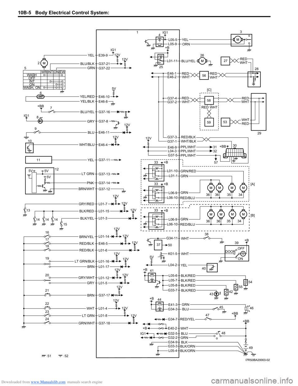
Downloaded from www.Manualslib.com manuals search engine 10B-5 Body Electrical Control System:
GRY/RED
BLK/YEL
BLK/RED
12V
12V
+BB
BLU/YEL
BLU
12V
WHT/BLU
12V
+BB
RED/YEL
G34-7
YEL/REDYEL/BLK
5V
IG1
IG1
IG1
WASH
OFFINT ON
WASH, ON WR EWON
INT
BLU/BLK
YELE39-9
GRN
12V12V
YELL05-5
BLU/YEL
PPL/WHT
12V
G37-5PPL/WHTPPL/WHT
+B +B
GRN/RED
GRN
GRN
RED/BLU
L06-9
L06-10
L01-10L01-1
ON
DOOR
OFF+B
+B
IG1 WHT
K01-5
12V
12V
12V
5V
12V
12V
L04-2YEL
RED/BLK
WHT
GRN/WHT
BRN
LT GRN/BLK
BRN
GRY/WHT
GRY
12VLT GRN
12V
12V
12V
12V
RED/BLK
LT GRN
BRN/WHT
5V5V
5V
PNK
+BB
GRNG32-2
+B
BLKBLK/ORNG34-9
G33-3
BLK/ORNL05-4
BLU
G32-5
WHTE40-2
G34-11
E41-3G34-3BLU
REDWHTREDWHT
+BB
1
2 3
4
5 67
8
9
10
11 12
13 14 14 14 15
16
17
18
19
20
21
22
23
24
52
51 25
26
28
30
31
32
33
33 36 36
+B
GRN
RED/BLU
L06-9
L06-10
33
36 3635 34
35 34
37 50 38
39
40
45 46
47
48 49
[B] [A]
[C]
G37-21
E46-10
GRY
YEL
BRN/YEL
L01-12
L01-4
L01-8
L01-11
GRN
WHT
G37-22
E46-4
G37-8
E46-8
G37-16
E46-11
G37-11
G37-13
G37-14
G37-12
L01-7
L01-15
L01-3
L01-14
L01-16
E46-5
L01-6
L01-17
L01-5
G37-17
G37-18
E46-1E46-2
E46-9
+B
12V
12V
BLK/RED
BLK/REDL05-6
G33-7 54
BLK/REDL05-7
55
BLK/REDL05-842
43
44
27REDWHT
57
+B41
56
ORNL05-9
L04-3
REDWHTREDWHT
REDWHT
REDWHT
G37-4G37-2
RED/BLKWHT/BLKG37-3G37-1 58
59
29
53
I7RS0BA20003-02
Page 1424 of 1496
Downloaded from www.Manualslib.com manuals search engine 10B-21 Body Electrical Control System:
DTC B1170 (No. 1170): EEPROM Access ErrorS7RS0BA204012
DTC Detecting Condition and Possible Cause
DTC Troubleshooting
NOTE
Before performing steps below, be sure to perform “Body Electrical Control System Check”.
1) Ignition switch OFF.
2) Replace BCM.
3) Repeat BCM Check Flow Table.
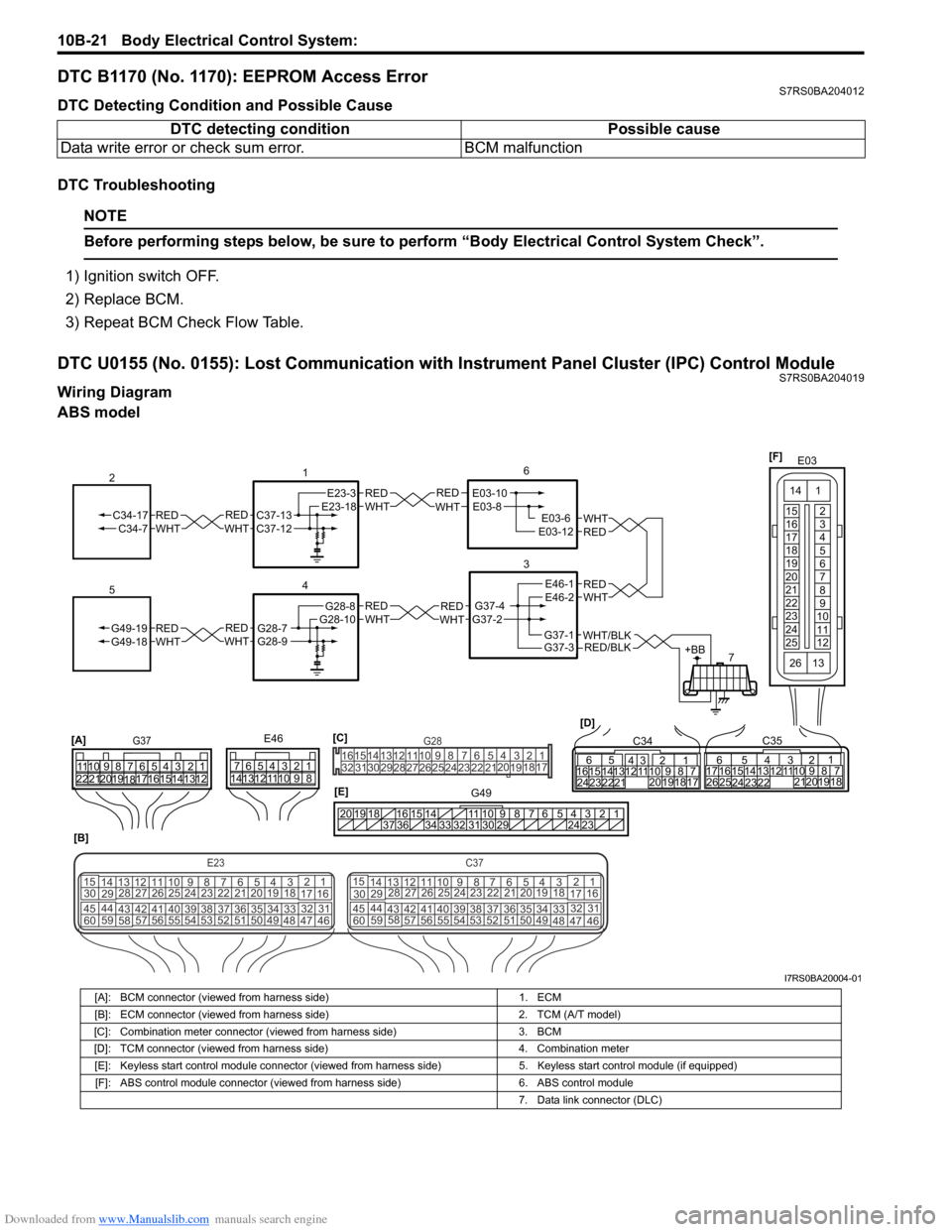
DTC U0155 (No. 0155): Lost Communication with Instrument Panel Cluster (IPC) Control ModuleS7RS0BA204019
Wiring Diagram
ABS model DTC detecting condition Possible cause
Data write error or check sum error. BCM malfunction
REDWHTE03-6E03-12
6
3
7
REDWHT
1
[B]
[A]
G37E46
1234567
1234567
8910
11
8910
11
121314 121314
151617
18
19202122 [D]65
1615 141312 11 43
2423 2122 10 9 8 7
21
1920 1817
C3417 16
26 2515 14
65 3
42
13 12
23 2224 1110 9
212019 87
18
1
C35
[E]
REDWHTC37-13C37-12REDWHTC34-17C34-7
2
12345678910
11
141516
36 34 33 32 31 30 29 24 23
37
181920
[C] [F]
G49
E23-3E23-18
4
REDWHTG28-7G28-9REDWHTG49-19G49-18
5
REDWHTE03-10E03-8
G37-4G37-2
REDWHTE46-1E46-2REDWHTREDWHTG28-8G28-10
E03
15
16
17
18
19
20
21
22
23
24
25 2
3
4
5
6
7
8
9
10
11
12
1
13
14
26
E23C37
34
1819
567
1011
17
20
47 46
495051
2122
52 16
25 9
24
14
29
5557 54 53
59
60 58 2
262728
15
30
56 4832 31
34353637
4042 39 38
44
45 43 41 33 1
1213
238
34
1819
567
1011
17
20
47 46
495051
2122
52 16
25 9
24
14
29
5557 54 53
59
60 58 2
262728
15
30
56 4832 31
34353637
4042 39 38
44
45 43 41 331
1213
238
G281234567
8
910111213141516
1718
19
20
212223242526272829303132
RED/BLKWHT/BLKG37-3G37-1+BB
I7RS0BA20004-01
[A]: BCM connector (viewed from harness side) 1. ECM
[B]: ECM connector (viewed from harness side) 2. TCM (A/T model)
[C]: Combination meter connector (viewed from harness side) 3. BCM
[D]: TCM connector (viewed from harness side) 4. Combination meter
[E]: Keyless start control module connector (viewed from harness side) 5. Keyless start control module (if equipped)
[F]: ABS control module connector (viewed from harness side) 6. ABS control module
7. Data link connector (DLC)
Page 1425 of 1496
Downloaded from www.Manualslib.com manuals search engine Body Electrical Control System: 10B-22
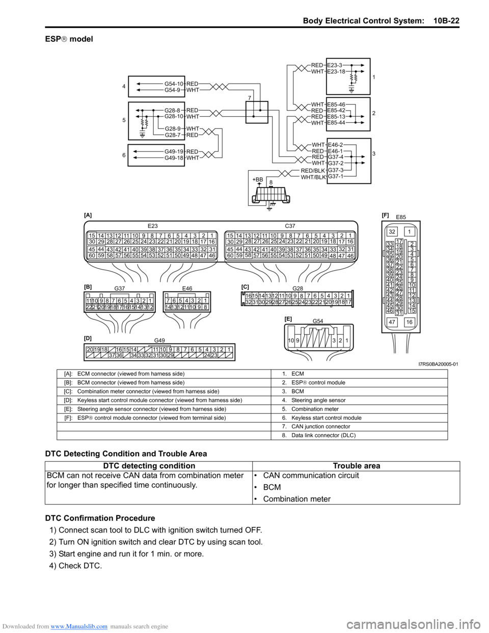
ESP® model
DTC Detecting Condition and Trouble Area
DTC Confirmation Procedure 1) Connect scan tool to DLC with ignition switch turned OFF.
2) Turn ON ignition switch and clear DTC by using scan tool.
3) Start engine and run it for 1 min. or more.
4) Check DTC.
[F] E85
161
15
2
3
4
5
6
7
8
9
10
11
12
13
14
17
18
19
20
21
22
23
24
25
26
27
28
29
30
31
3233
34
35
36
37
38
39
40
41
42
43
44
45
46
47
[D] 12345678910
11
141516
36 34 33 32 31 30 29 24 23
37
181920
G49
[A]
E23
C37
34
1819
567
10
11
17
20
47 46
495051
2122
52 16
25 9
24
14
29
5557 54 53
59
60 58 2
262728
15
30
56 4832 31
34353637
4042 39 38
44
45 43 41 331
1213
238
34
1819
567
10
11
17
20
47 46
495051
2122
52 16
25 9
24
14
29
5557 54 53
59
60 58 2
262728
15
30
56 4832 31
34353637
4042 39 38
44
45 43 41 331
12
13
238
[C]G28
1234567
8
910
11
1213141516
1718
19
20
212223242526272829303132
[E] G54
109 321
[B]
G37E46
1234567 1234567
8910
11
8910
11
121314 121314
1516171819202122
4
6 1
2
3
REDWHT
REDWHT
REDWHT
REDWHT
E23-3E23-18
E85-42E85-46
E85-13E85-44
G37-4G37-2
REDWHT
REDWHTG49-19G49-18
5
7
WHTG54-9REDG54-10
G28-8G28-10
G28-7REDG28-9WHT
RED/BLKWHT/BLK
REDWHTE46-1E46-2
G37-1G37-3
+BB8
I7RS0BA20005-01
[A]: ECM connector (viewed from harness side)
1. ECM
[B]: BCM connector (viewed from harness side) 2. ESP® control module
[C]: Combination meter connector (viewed from harness side) 3. BCM
[D]: Keyless start control module connector (viewed from harness side) 4. Steering angle sensor
[E]: Steering angle sensor connector (viewed from harness side) 5. Combination meter
[F]: ESP ® control module connector (viewed from terminal side) 6. Keyless start control module
7. CAN junction connector
8. Data link connector (DLC)
DTC detecting condition Trouble area
BCM can not receive CAN data from combination meter
for longer than specif ied time continuously. • CAN communication circuit
•BCM
• Combination meter
Page 1436 of 1496
Downloaded from www.Manualslib.com manuals search engine 10B-33 Body Electrical Control System:
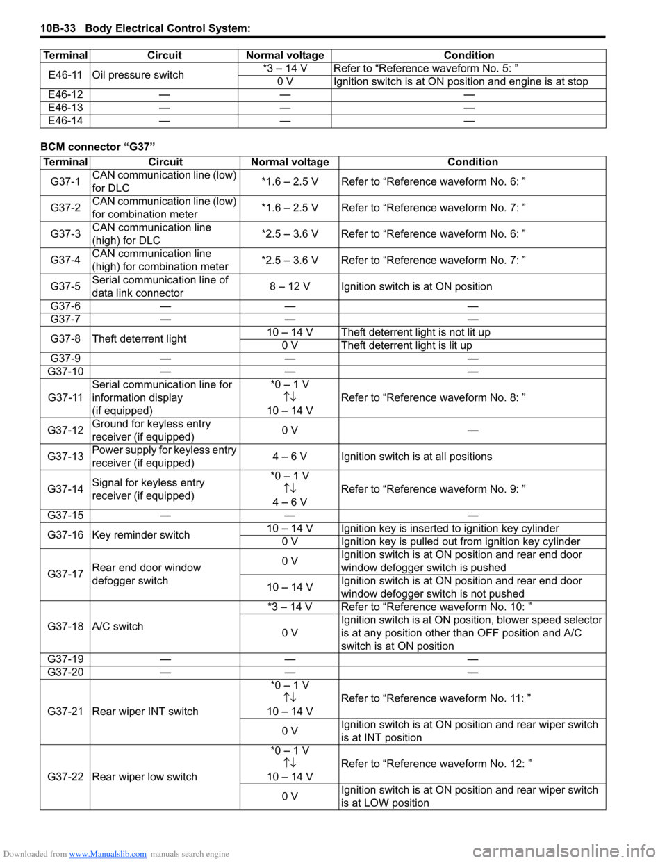
BCM connector “G37”E46-11 Oil pressure switch
*3 – 14 V Refer to “Reference waveform No. 5: ”
0 V Ignition switch is at ON position and engine is at stop
E46-12 — — —
E46-13 — — —
E46-14 — — —
Terminal Circuit Normal voltage Condition
Terminal
CircuitNormal voltage Condition
G37-1 CAN communication line (low)
for DLC *1.6 – 2.5 V Refer to “Reference waveform No. 6: ”
G37-2 CAN communication line (low)
for combination meter *1.6 – 2.5 V Refer to “Reference waveform No. 7: ”
G37-3 CAN communication line
(high) for DLC *2.5 – 3.6 V Refer to “Reference waveform No. 6: ”
G37-4 CAN communication line
(high) for combination meter *2.5 – 3.6 V Refer to “Reference waveform No. 7: ”
G37-5 Serial communication line of
data link connector 8 – 12 V Ignition switch is at ON position
G37-6 — — —
G37-7 — — —
G37-8 Theft deterrent light 10 – 14 V Theft deterrent light is not lit up
0 V Theft deterrent light is lit up
G37-9 — — —
G37-10 — — —
G37-11 Serial communication line for
information display
(if equipped) *0 – 1 V
↑↓
10 – 14 V Refer to “Reference
waveform No. 8: ”
G37-12 Ground for keyless entry
receiver (if equipped) 0 V
—
G37-13 Power supply for keyless entry
receiver (if equipped) 4 – 6 V Ignition switch is at all positions
G37-14 Signal for keyless entry
receiver (if equipped) *0 – 1 V
↑↓
4 – 6 V Refer to “Reference
waveform No. 9: ”
G37-15 — — —
G37-16 Key reminder switch 10 – 14 V Ignition key is inserted to ignition key cylinder
0 V Ignition key is pulled out from ignition key cylinder
G37-17 Rear end door window
defogger switch 0 V
Ignition switch is at ON
position and rear end door
window defogger switch is pushed
10 – 14 V Ignition switch is at ON
position and rear end door
window defogger switch is not pushed
G37-18 A/C switch *3 – 14 V Refer to “Reference waveform No. 10: ”
0 V Ignition switch is at ON pos
ition, blower speed selector
is at any position other than OFF position and A/C
switch is at ON position
G37-19 — — —
G37-20 — — —
G37-21 Rear wiper INT switch *0 – 1 V
↑↓
10 – 14 V Refer to “Reference
waveform No. 11: ”
0 V Ignition switch is at ON pos
ition and rear wiper switch
is at INT position
G37-22 Rear wiper low switch *0 – 1 V
↑↓
10 – 14 V Refer to “Reference
waveform No. 12: ”
0 V Ignition switch is at ON pos
ition and rear wiper switch
is at LOW position