a-2 SUZUKI SWIFT 2006 2.G Service Repair Manual
[x] Cancel search | Manufacturer: SUZUKI, Model Year: 2006, Model line: SWIFT, Model: SUZUKI SWIFT 2006 2.GPages: 1496, PDF Size: 34.44 MB
Page 867 of 1496

Downloaded from www.Manualslib.com manuals search engine Table of Contents 6- i
6
Section 6
CONTENTS
Steering
Precautions ................................................. 6-1
Precautions............................................................. 6-1
Precautions on Steering........................................ 6-1
Steering General Diagnosi s.................... 6A-1
Precautions........................................................... 6A-1
Precautions for Steering Diagnosis ..................... 6A-1
Diagnostic Information and Procedures ............ 6A-2 Steering Symptom Diagnosis .............................. 6A-2
Steering Wheel and Column ................... 6B-1
Precautions........................................................... 6B-1
Service Precautions of Steering Wheel and Column.............................................................. 6B-1
General Description ............................................. 6B-1 Steering Wheel and Column Construction .......... 6B-1
Diagnostic Information and Procedures ............ 6B-2 Checking Steering Column for Accident Damage ............................................................ 6B-2
Repair Instructions .............................................. 6B-3 Steering Wheel and Column Construction .......... 6B-3
Steering Wheel Removal and Installation ........... 6B-4
Contact Coil Cable Assembly Removal and Installation ......................................................... 6B-5
Centering Contact Coil Cable Assembly ............. 6B-6
Contact Coil Cable Assembly Inspection ............ 6B-6
Steering Angle Sensor Removal and Installation ......................................................... 6B-6
Steering Angle Sensor Inspection ....................... 6B-6
Steering Column Removal and Installation ......... 6B-7
Steering Column Inspecti on ................................ 6B-8
Ignition Switch Cylinder Assembly Removal and Installation (Non- Keyless Start Model)...... 6B-9
Steering Lock Assembly (Ignition Switch) Removal and Installation................................... 6B-9
Steering Lower Shaft Removal and Installation ....................................................... 6B-10
Specifications ..................................................... 6B-11
Tightening Torque Specifications ...................... 6B-11
Special Tools and Equipmen t ........................... 6B-11
Special Tool ...................................................... 6B-11
Power Assisted Steering System........... 6C-1
Precautions........................................................... 6C-1 Steering System Note .........................................6C-1
Precautions in Diagnosing Troubles ...................6C-1
General Description .............................................6C-2 P/S System Description ......................................6C-2
EPS Diagnosis General Descr iption ...................6C-3
On-Board Diagnostic System Description ...........6C-3
Schematic and Routing Diagram ........................6C-4 EPS System Wiring Circuit Diagram ...................6C-4
Diagnostic Information and Procedures ............6C-5 EPS System Check .............. ...............................6C-5
“EPS” Warning Light Check . ...............................6C-8
DTC Check..........................................................6C-8
DTC Clearance ...................................................6C-9
DTC Table ...........................................................6C-9
Scan Tool Data .................................................6C-11
Visual Inspection ...............................................6C-12
P/S System Symptom Diagnosis ......................6C-12
Serial Data Link Circuit Check ..........................6C-13
“EPS” Warning Light Do es Not Come ON with
Ignition Switch Turn ed ON before Engine
Starts ...............................................................6C-15
“EPS” Warning Light Remains ON Steady after Engine Starts ..........................................6C-16
DTC C1113: Steering Torque Sensor (Main and Sub) Circuit Correlation ............................6C-17
DTC C1114: Steering Torque Sensor Reference Power Supply Circuit .....................6C-19
DTC C1117: Steering Torque Sensor Failure Signal Circuit Low ...........................................6C-21
DTC C1118: Steering Torque Sensor Failure Signal Circuit High...........................................6C-22
DTC C1119: Steering Torque Sensor Power Supply Circuit ..................................................6C-24
DTC C1121 / C1123 / C1124: VSS Circuit
Failure .............................................................6C-26
DTC C1122: Engine Speed Signal....................6C-28
DTC C1141 / C1142 / C1143 / C1145: P/S Motor Circuit Failure ........................................6C-30
DTC C1153: P/S Control Module Power Supply Circuit Voltage Low .............................6C-32
DTC C1155: P/S Control Module Failure ..........6C-33
P/S Control Module Power Supply and Ground Circuit Check ......................................6C-34
Inspection of P/S Control Module and Its Circuits ............................................................6C-35
Page 871 of 1496

Downloaded from www.Manualslib.com manuals search engine Steering General Diagnosis: 6A-2
Diagnostic Information and Procedures
Steering Symptom DiagnosisS7RS0B6104001
ConditionPossible cause Correction / Reference Item
Hard steering Tire not adequately inflated Inflate tires to proper pressure.
Malfunction of power steering system Check and correct.
Bind in tie-rod end ball studs or lower
ball joints Replace tie-rod end or front suspension arm.
Disturbed front wheel alignment Check and adjust front wheel alignment.
Bind in steering column Repair or replace steering column.
Rack and pinion adjustment Check and adjustment rack and pinion torque.
Too much play in steering Wheel bearings worn Replace wheel bearing.
Loose steering gear case bolts Tighten gear case bolts.
Faulty steering gear case assembly Replace steering gear case assembly.
Worn steering shaft joints Replace joint.
Worn tie-rod ends or tie-rod inside ball
joints Replace tie-rod end or tie-rod.
Worn lower ball joints Replace front suspension control arm.
Rack and pinion adjustment Check and adjustment rack and pinion torque.
Poor return ability Bind in tie-rod end ball studs Replace tie-rod end.
Bind in ball joints Replace front suspension control arm.
Bind in steering column Repair or replace steering column.
Disturbed front end alignment Check and adjust front end alignment.
Faulty steering gear case assembly Replace steering gear case assembly.
Tires not adequately inflated Adjust tire pressure.
Rack and pinion adjustment Check and adjustment rack and pinion torque.
Rack and pinion noise
(Rattle or chuckle) Loose steering gear case bolts
Tighten steering gear case bolts.
Rack and pinion adjustment Check and adjustment rack and pinion torque.
Faulty steering gear case assembly Replace steering gear case assembly.
Broken or other wise damaged wheel
bearing(s) Replace wheel bearing(s).
Wander or poor steering
stability Mismatched or uneven tires
Replace or inflate tires to proper pressure.
Loosen ball joints and tie-rod ends Replace suspension control arm or tie-rod end.
Faulty struts or mountings Replace strut or repair mounting.
Loose stabilizer bar Tighten or replace stabilizer bar or bush.
Broken or sagging springs Replace spring.
Rack and pinion adjustment Check and adjustment rack and pinion torque.
Disturbed front wheel alignment Check and adjust front wheel alignment.
Faulty steering gear case assembly Replace steering gear case assembly.
Erratic steering when
braking Worn wheel bearing(s)
Replace wheel bearing(s).
Broken or sagging spring(s) Replace coil spring(s).
Wheel tires are inflated unequally Inflate tires to proper pressure.
Disturbed front wheel alignment Check and adjust front wheel alignment.
Brakes not working in unison Check and repair brake system.
Leaking caliper Repair or replace caliper.
Warped discs Replace brake disc.
Badly worn brake pads Replace brake pads.
Page 933 of 1496

Downloaded from www.Manualslib.com manuals search engine Table of Contents 7- i
7
Section 7
CONTENTS
HVAC
Precautions ................................................. 7-1
Precautions............................................................. 7-1
Precautions on HVAC ........................................... 7-1
Heater and Ventilation.... ......................... 7A-1
General Description ............................................. 7A-1
Heater and Ventilation Construction ................... 7A-1
Schematic and Routing Diagram ........................ 7A-2 Heater and Ventilation Wiring Circuit Diagram .... 7A-2
Diagnostic Information and Procedures ............ 7A-3 Heater and Ventilation Symptom Diagnosis........ 7A-3
Repair Instructions .............................................. 7A-4 HVAC Unit Components ..................................... 7A-4
HVAC Unit Removal and Installation .................. 7A-4
Blower Motor Removal and Installation............... 7A-4
Blower Motor Inspection ..................................... 7A-4
Blower Motor Resistor Removal and Installation ......................................................... 7A-5
Blower Motor Resistor Inspection ....................... 7A-5
Blower Motor Relay Inspection ........................... 7A-6
HVAC Control Unit Components ......................... 7A-6
HVAC Control Unit Remova l and Installation ...... 7A-7
Blower Speed Selector In spection ...................... 7A-9
Air Intake Selector Inspec tion ............................. 7A-9
Air Intake Control Actuator Removal and Installation ......................................................... 7A-9
Air Intake Control Actuator Inspection .............. 7A-10
Center Ventilation Louver Removal and Installation ....................................................... 7A-10
Side Ventilation Louver Removal and Installation ....................................................... 7A-11
HVAC Air Filter Removal and Installation (If Equipped)........................................................ 7A-12
HVAC Air Filter Inspection (If Equipped) ........... 7A-12
Air Conditioning System... ...................... 7B-1
Manual Type ............................................................ 7B-1
Precautions........................................................... 7B-1A/C System Caution ............................................ 7B-1
Precautions on Servicing A/C System ................ 7B-1
General Description ............................................. 7B-3 Refrigerant Type Identifica tion ............................ 7B-3
Sub-Cool A/C System Description ...................... 7B-4
A/C Operation Description .................................. 7B-4 Schematic and Routing Diagram ........................7B-5
Major Components of A/C System ...................... 7B-5
A/C System Wiring Diagram ............................... 7B-6
Diagnostic Information and Procedures ............7B-7 A/C System Symptom Diagnosis ........................ 7B-7
Abnormal Noise Sympto m Diagnosis of A/C
System .............................................................. 7B-9
A/C System Performance Inspection ................ 7B-10
A/C System Inspection at ECM ......................... 7B-15
Repair Instructions ........... .................................7B-16
Operation Procedure for Re frigerant Charge .... 7B-16
Condenser Assembly On-Vehicle Inspection .... 7B-21
Condenser Assembly Removal and Installation ....................................................... 7B-21
Receiver/Dryer Removal and Installation .......... 7B-22
HVAC Unit Components ................................... 7B-23
HVAC Unit Removal and In stallation ................ 7B-24
Evaporator Inspection ....................................... 7B-24
Evaporator Thermistor (Evaporator Temperature Sensor) Removal and
Installation ....................................................... 7B-25
Evaporator Thermistor (Evaporator Temperature Sensor) Inspec tion..................... 7B-25
Expansion Valve Removal and Installation ....... 7B-26
Expansion Valve Inspection .............................. 7B-26
A/C Refrigerant Pressure Sensor and Its Circuit Inspection............................................. 7B-26
A/C Refrigerant Pressu re Sensor Removal
and Installation ................................................ 7B-26
A/C Switch Inspection ....................................... 7B-27
Compressor Relay Inspection ........................... 7B-27
Compressor Drive Belt Inspection and Adjustment ...................................................... 7B-27
Compressor Drive Belt Removal and Installation ....................................................... 7B-28
Compressor Assembly Removal and Installation ....................................................... 7B-28
Compressor Assembly Components................. 7B-29
Magnet Clutch Inspection.................................. 7B-29
Magnet Clutch Removal and Installation........... 7B-29
Relief Valve Inspection...................................... 7B-31
Relief Valve Removal and Installation............... 7B-32
Specifications .................... .................................7B-32
Tightening Torque Specifications ...................... 7B-32
Special Tools and Equipmen t ...........................7B-33
Page 938 of 1496
Downloaded from www.Manualslib.com manuals search engine 7A-2 Heater and Ventilation:
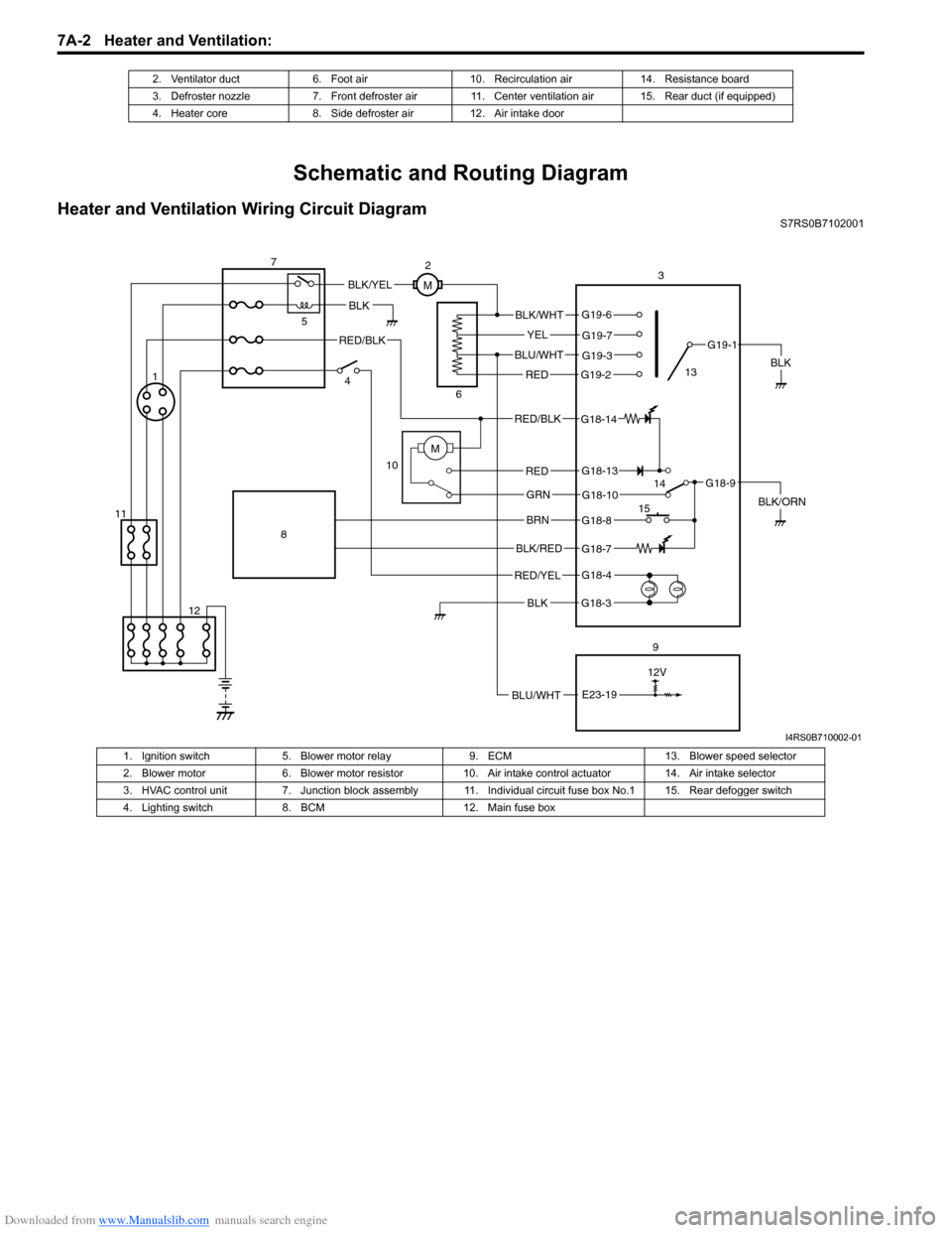
Schematic and Routing Diagram
Heater and Ventilation Wiring Circuit DiagramS7RS0B7102001
2. Ventilator duct 6. Foot air 10. Recirculation air 14. Resistance board
3. Defroster nozzle 7. Front defroster air 11. Center ventilation air 15. Rear duct (if equipped)
4. Heater core 8. Side defroster air 12. Air intake door
BLK
RED/BLK
3
5
7
BLK
2
M
12V
BLU/WHTE23-19
G18-3
G18-4
G18-7
G18-8
G18-10
G18-13
G19-2
G19-3
G19-7
G19-6
G19-1
G18-9
G18-14
BLK/WHT
YEL
BLU/WHT
RED
RED/BLK
RED
GRN
BRN
BLK/RED
RED/YEL
BLK
BLK/YEL
BLK/ORN
4
6
10
8
9
M1
12
11 13
14
15
I4RS0B710002-01
1. Ignition switch 5. Blower motor relay 9. ECM 13. Blower speed selector
2. Blower motor 6. Blower motor resistor 10. Air intake control actuator 14. Air intake selector
3. HVAC control unit 7. Junction block assembly 11. Ind ividual circuit fuse box No.1 15. Rear defogger switch
4. Lighting switch 8. BCM 12. Main fuse box
Page 1029 of 1496
Downloaded from www.Manualslib.com manuals search engine Table of Contents 8- i
8
Section 8
CONTENTS
Restraint
Precautions ................................................. 8-1
Precautions............................................................. 8-1
Precautions on Restraint ....................................... 8-1
Seat Belts .......... ............................... ........ 8A-1
Precautions........................................................... 8A-1
Precautions on Service a nd Diagnosis of Seat
Belt .................................................................... 8A-1
General Description ............................................. 8A-1 Seat Belt Construction ........................................ 8A-1
Diagnostic Information and Procedures ............ 8A-2 Repair and Inspection Required after Accident ............................................................ 8A-2
Repair Instructions .............................................. 8A-3 Front Seat Belt Components ............................... 8A-3
Front Seat Belt Removal and Installation ............ 8A-4
Front Seat Belt Inspection ................................... 8A-4
Rear Seat Belt Components ............................... 8A-6
Rear Seat Belt Removal and Installation ............ 8A-7
Rear Seat Belt Inspection ................................... 8A-7
Specifications ....................................................... 8A-7
Tightening Torque Specifications ........................ 8A-7
Air Bag System ............... ......................... 8B-1
Precautions........................................................... 8B-1
Precautions on Service and Diagnosis of Air Bag System....................................................... 8B-1
Precautions on Handling and Storage of Air Bag System Components . ................................ 8B-2
Precautions on Disposal of Air Bag and Seat
Belt Pretensioner .............................................. 8B-5
General Description ............................................. 8B-5 Air Bag System Construction .............................. 8B-5
Air Bag System Input / Output Table .................. 8B-6
Schematic and Routing Diagram ........................ 8B-7 Air Bag System Wiring Circuit Diagram .............. 8B-7
Component Locatio n ........................................... 8B-9
Air Bag System Components, Wiring and Connectors Location ......................................... 8B-9
Diagnostic Information and Procedures .......... 8B-10 Air Bag Diagnostic System Check .................... 8B-10
Air Bag Diagnostic System Check Flow ............ 8B-10
DTC Table ......................................................... 8B-11
DTC Check ....................................................... 8B-12 DTC Clearance ................................................. 8B-12
Scan Tool Data ................................................. 8B-13
“AIR BAG” Warning Right Comes ON Steady .. 8B-13
“AIR BAG” Warning Right Does Not Come
ON ................................................................... 8B-15
“AIR BAG” Warning Right Flashes .................... 8B-16
DTC B1013: SDM fault...................................... 8B-17
DTC B1014: “AIR BAG” Warning Right Circuit Failure ............................................................. 8B-17
DTC B1016: Power Source Voltage High ......... 8B-18
DTC B1017: Power Source Voltage Low .......... 8B-20
DTC B1021: Front Air Bag Module Deployed ... 8B-22
DTC B1024 / B1025: Side-Air Bag (Driver / Passenger) Deployed...................................... 8B-22
DTC B1026: Pretensioner Activated ................. 8B-23
DTC B1027: Reusable Number Exceeded ....... 8B-24
DTC B1031: Driver Air Bag Initiator Circuit
Resistance High .............................................. 8B-24
DTC B1032: Driver Air Bag Initiator Circuit
Resistance Low ............................................... 8B-29
DTC B1033: Driver Air Bag Initiator Circuit
Short to Ground............................................... 8B-34
DTC B1034: Driver Air Bag Initiator Circuit
Short to Power Circuit .... ................................. 8B-39
DTC B1041: Passenger Air Bag Initiator Circuit Resistance High ................................... 8B-44
DTC B1042: Passenger Air Bag Initiator Circuit Resistance Low.................................... 8B-47
DTC B1043: Passenger Air Bag Initiator Circuit Short to Ground ................................... 8B-50
DTC B1044: Passenger Air Bag Initiator Circuit Short to Power Circ uit .......................... 8B-53
DTC B1051 / B1055: Driver / Passenger Pretensioner Initiator Circuit Resistance
High ................................................................. 8B-56
DTC B1052 / B1056: Driver / Passenger Pretensioner Initiator Circu it Resistance Low .. 8B-58
DTC B1053 / B1057: Driver / Passenger Pretensioner Initiator Circuit Short to Ground .. 8B-60
DTC B1054 / B1058: Driver / Passenger Pretensioner Initiator Circuit Short to Power
Circuit .............................................................. 8B-62
DTC B1061 / B1065: Driver / Passenger Side- Air Bag Initiator Circuit Resistance High ......... 8B-64
Page 1033 of 1496
Downloaded from www.Manualslib.com manuals search engine Seat Belts: 8A-2
Seat Belt with ELR
The seat belt with emergency locking retractor (ELR) is
designed so that it locks immediately (to prevent the
webbing from being pulled out of the retractor any
further) when any of the following items is detected as
exceeding each set value;
• Speed at which the webbing is pulled out of the retractor.
• Acceleration or deceleration of the vehicle speed.
• Inclination.
Seat Belt with A-ELR
The automatic and emergency locking retractor (A-ELR)
works as an Emergency Locking Retractor (ELR) till its
webbing is pulled all the way out and then on as an
Automatic Locking Retractor (ALR ) till it is retracted fully.
ALR: Automatically locks when the webbing is pulled out
from the retractor and allowed to retract even a little.
Then the webbing can not be pulled out any further,
unless it is wound all the way back into the retractor,
which releases the lock and allows the webbing to be
pulled out.
Seat Belt with ELR and Pretensioner
The seat belt with ELR and a pretensioner has a
pretensioner mechanism whic h operates in linkage with
the air bag in addition to the described ELR.
The pretensioner is incorporated in retractor assembly
and controlled by SDM as one of air bag system
components. It will be activated at the same time as the
driver and passenger air bag module when an impact at
the front of vehicle exceeds the specified value.
When servicing seat belt (retractor assembly) with
pretensioner, be sure to observe all WARNINGS and
CAUTIONS and “Precautions on Service and Diagnosis
of Air Bag System in Section 8B”. CAUTION!
Do not reuse the seat belt pretensioner
(retractor assembly) that has activated.
Replace it with a new seat belt assembly and
buckle together as a set. For checking
procedure of its activation, refer to “Repair
and Inspection Required after Accident in
Section 8B”.
Seat Belt Remainder
When driver’s seat belt is unfastened (under the
following conditions), seat belt reminder light and
warning buzzer inform that driver’s seat belt is
unfastened. Seat belt reminder light located in
combination meter and warning buzzer located inside
BCM operate as follows:
• Seat belt reminder light comes on when driver’s seat belt is unfastened while igni tion key switch is at ON
position.
• If vehicle speed exceeds 15 km/h with seat belt unfastened, warning buzzer operates for
approximately 95 seconds and seat belt reminder light
flashes synchronously with buzzer. When warning
buzzer stops operating, seat belt reminder light is
turned on.
• If driver’s seat belt state is changed from “fastened” to “unfastened” while vehicle speed is above 15 km/h,
warning buzzer operates for approximately 95
seconds and seat belt reminder light flashes
synchronously with buzzer. When warning buzzer
stops operating, seat belt reminder light is turned on.
Diagnostic Information and Procedures
Repair and Inspection Required after AccidentS7RS0B8104001
After an accident, whether the seat belt pretensioner has been activated or not, be sure to perform checks and repairs
described on “Repair and Inspection Required after Accident in Section 8B”.
Page 1167 of 1496

Downloaded from www.Manualslib.com manuals search engine Table of Contents 9- i
9
Section 9
CONTENTS
Body, Cab and Accessories
Precautions ................................................. 9-1
Precautions............................................................. 9-1
Precautions on Body, Cab and Accessories ......... 9-1
Precautions for Body Service ................................ 9-1
Fastener Caution for Body Service ....................... 9-1
Wiring Systems............... ......................... 9A-1
Precautions........................................................... 9A-1
Cautions in Body Electrical System Servicing..... 9A-1
General Description ............................................. 9A-1 Abbreviations ...................................................... 9A-1
Wire / Connector Color Sy mbols ......................... 9A-1
Symbols and Marks ............................................ 9A-2
How to Read Connector Layout Diagram ........... 9A-4
How to Read Connector Codes and Terminal Nos.................................................................... 9A-5
How to Read Ground Point ................................. 9A-7
How to Read Power Supply Diagram.................. 9A-8
How to Read System Circuit Diagram................. 9A-8
Connector Layout Diagram . .............................. 9A-10
Connector Layout Diagram ............................... 9A-10
Engine Compartment .......... .............................. 9A-10
Instrument Panel ............................................... 9A-16
Door, Roof......................................................... 9A-20
Floor .................................................................. 9A-23
Rear .................................................................. 9A-29
Ground Point ...................................................... 9A-30 Ground (earth) Point ......................................... 9A-30
Power Supply Diagram ........ .............................. 9A-31
Power Supply Diagram ....... .............................. 9A-31
Fuses and the Protected Parts ......................... 9A-33
Fuses in Main Fuse Box (RHD) ........................ 9A-33
Fuses in Main Fuse Box (LHD) ......................... 9A-33
Individual Circuit Fuse Box No. 1 ...................... 9A-34
Individual Circuit Fuse Box No. 2 (In J/B) ......... 9A-35
Junction Block (J/B) Connector / Fuse Layout .. 9A-37
Junction Block Inner Circuit (Overview) ............ 9A-38
Junction Block Inner Circuit (Detail) .................. 9A-40
System Circuit Diagram... .................................. 9A-45
System Circuit Diagram .. .................................. 9A-45
A-1 Cranking System Circ uit Diagram .............. 9A-46
A-2 Charging System Circu it Diagram .............. 9A-47
A-3 Ignition System Circu it Diagram ................. 9A-48
A-4 Cooling System Circuit Diagram................. 9A-49 A-5 Engine and A/C Control System Circuit
Diagram........................................................... 9A-50
A-6 A/T Control System Circuit Diagram........... 9A-55
A-7 Immobilizer System Circuit Diagram .......... 9A-57
A-8 Body Control System Circuit Diagram ........ 9A-58
B-1 Windshield Wiper and Washer Circuit Diagram........................................................... 9A-62
B-2 Rear Wiper and Washer Circuit Diagram ... 9A-63
B-3 Rear Defogger Circuit Diagram .................. 9A-64
B-4 Power Window Circuit Diagram .................. 9A-65
B-5 Power Door Lock Circu it Diagram .............. 9A-67
B-6 Power Mirror Circuit Diagram ..................... 9A-69
B-7 Horn Circuit Diagram .................................. 9A-70
B-8 Seat Heater Circuit Diagram....................... 9A-71
B-9 Keyless Start System Circuit Diagram........ 9A-72
C-1 Combination Mete r Circuit Diagram
(Meter)............................................................. 9A-73
C-2 Combination Mete r Circuit Diagram
(Indicator) ........................................................ 9A-74
C-3 Combination Mete r Circuit Diagram
(Warning Light)................................................ 9A-75
D-1 Headlight System Circuit Diagram ............. 9A-77
D-2 Position, Tail and Licence Plate Light System Circuit Diagram .................................. 9A-79
D-3 Front Fog Light System Circuit Diagram .... 9A-80
D-4 Illumination Light System Circuit Diagram .. 9A-81
D-5 Interior Light System Circuit Diagram......... 9A-82
D-6 Turn Signal and Hazard Warning Light System Circuit Diagram .................................. 9A-83
D-7 Brake Light System Circuit Diagram .......... 9A-85
D-8 Back-Up Light System Circuit Diagram ...... 9A-86
D-9 Headlight Beam Leveling System Circuit Diagram........................................................... 9A-87
D-10 Rear Fog Light Circuit Diagram ................ 9A-88
E-1 Heater System Circuit Diagram .................. 9A-89
E-2 Auto A/C System Circuit Diagram .............. 9A-91
F-1 Air-Bag System Circuit Diagram ................. 9A-93
F-2 Anti-Lock Brake System Circuit Diagram.... 9A-95
F-3 Electronic Stab ility Program System
Circuit Diagram .................. ............................. 9A-97
F-4 Power Steering System Circuit Diagram .... 9A-99
G-1 Audio System Circuit Diagram ................. 9A-101
G-2 Multi Information Display / Accessory Socket System Circuit Diagram .................... 9A-102
List of Connector .............................................9A-103
Page 1173 of 1496
Downloaded from www.Manualslib.com manuals search engine Wiring Systems: 9A-2
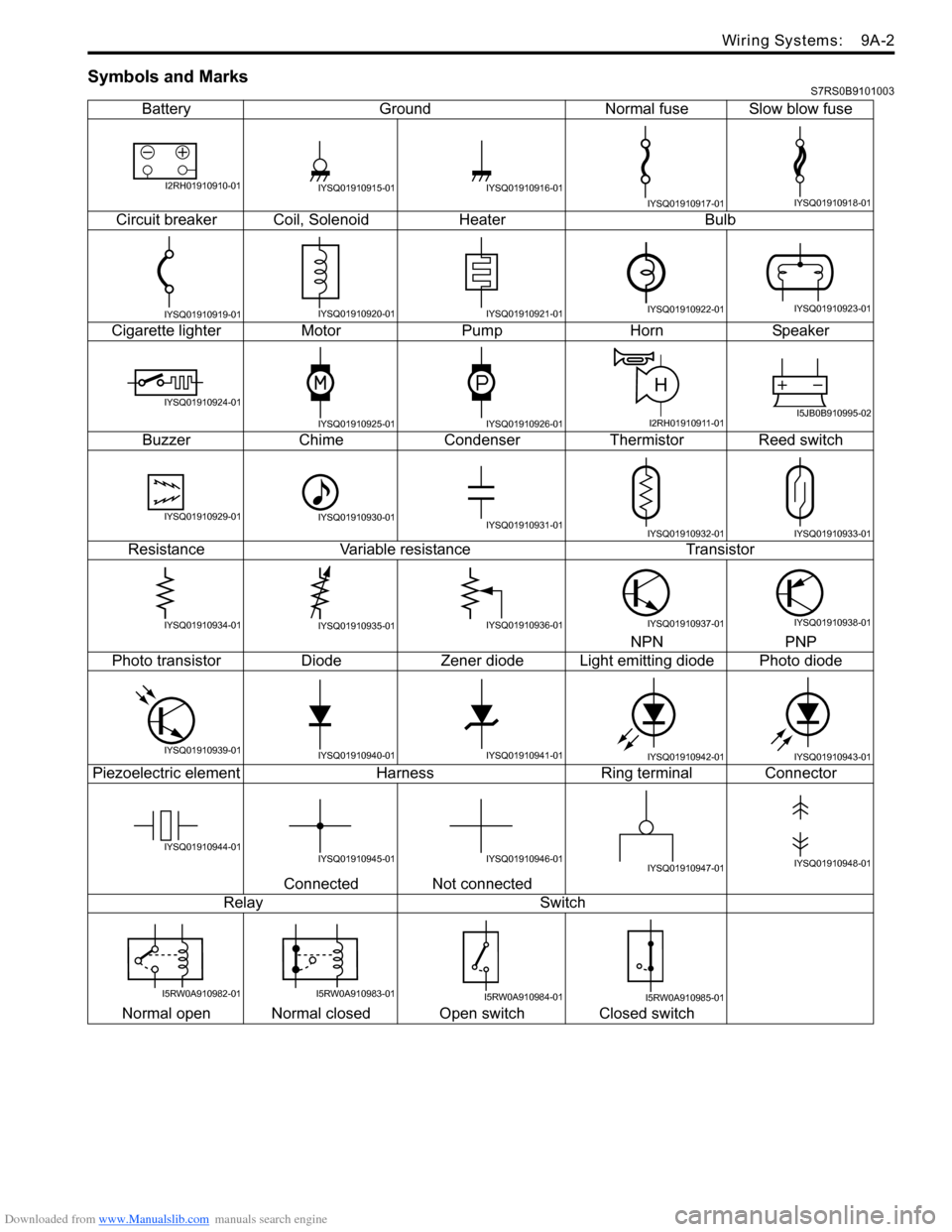
Symbols and MarksS7RS0B9101003
BatteryGroundNormal fuse Slow blow fuse
Circuit breaker Coil, SolenoidHeater Bulb
Cigarette lighter MotorPump HornSpeaker
Buzzer ChimeCondenser Thermistor Reed switch
Resistance Variable resistance Transistor
NPN PNP
Photo transistor DiodeZener diode L ight emitting diode Photo diode
Piezoelectric element Harness Ring terminal Connector
Connected Not connected
Relay Switch
Normal open Normal closed Open switch Closed switch
I2RH01910910-01IYSQ01910915-01IYSQ01910916-01
IYSQ01910917-01IYSQ01910918-01
IYSQ01910919-01IYSQ01910920-01IYSQ01910921-01IYSQ01910922-01IYSQ01910923-01
IYSQ01910924-01
IYSQ01910925-01IYSQ01910926-01
H
I2RH01910911-01I5JB0B910995-02
IYSQ01910929-01IYSQ01910930-01IYSQ01910931-01IYSQ01910932-01IYSQ01910933-01
IYSQ01910934-01IYSQ01910935-01IYSQ01910936-01IYSQ01910937-01IYSQ01910938-01
IYSQ01910939-01IYSQ01910940-01IYSQ01910941-01IYSQ01910942-01IYSQ01910943-01
IYSQ01910944-01IYSQ01910945-01IYSQ01910946-01IYSQ01910947-01IYSQ01910948-01
I5RW0A910982-01I5RW0A910983-01I5RW0A910984-01I5RW0A910985-01
Page 1175 of 1496
![SUZUKI SWIFT 2006 2.G Service Repair Manual Downloaded from www.Manualslib.com manuals search engine Wiring Systems: 9A-4
How to Read Connector Layout DiagramS7RS0B9101004
[A-1]: Harness symbol and corresponding harness name
A: Battery harness SUZUKI SWIFT 2006 2.G Service Repair Manual Downloaded from www.Manualslib.com manuals search engine Wiring Systems: 9A-4
How to Read Connector Layout DiagramS7RS0B9101004
[A-1]: Harness symbol and corresponding harness name
A: Battery harness](/img/20/7607/w960_7607-1174.png)
Downloaded from www.Manualslib.com manuals search engine Wiring Systems: 9A-4
How to Read Connector Layout DiagramS7RS0B9101004
[A-1]: Harness symbol and corresponding harness name
A: Battery harness
B: A/C harness
C: Engine harness
D: Injector harness
E: Main harness, Oil pressure switch wire, Console wire
G: Instrument panel harness
J: Side door wire (Power window)
K: Interior light harness, Rear speaker wire, Roof wire
L: Floor harness, G sensor wire (Fuel pump harness)
M: Rear bumper harness
O: Rear end door harness
Q: Air bag/Pretensioner harness
R: (Fuel pump wire)
[A-2]: Connector Number
[B]: Ground point No.
12
11
[B] [B]
Connector code
[A-1] [A-2]L 36
L13 L15
R01
L14
L12
L11L10
L09 L36
R02
L24
L25
L33
L28
L20 L26 (TO O01)
{
L05
L16
L32
L19
L01 (TO G01)
L02 (TO E04)
L03 (TO E05)
L42
R05
R04
L07 (TO K02)
I2RH01910901-01
Page 1191 of 1496
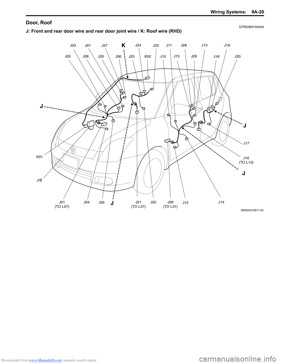
Downloaded from www.Manualslib.com manuals search engine Wiring Systems: 9A-20
Door, RoofS7RS0B910A004
J: Front and rear door wire and rear door joint wire / K: Roof wire (RHD)
K02
K
K01
J/B
J04J21
(TO L37)
J02
J03
J06
J07J27
J08J26 J25J23
J24
JJ01
(TO L07) J22J09
(TO L31)J12
J10
J13
J18
J19
J20
J J
J17
J16
(TO L13)
J14
J11
J28
J15
J29
J05
J
I5RS0C910911-03