clearance SUZUKI SWIFT 2006 2.G Service Repair Manual
[x] Cancel search | Manufacturer: SUZUKI, Model Year: 2006, Model line: SWIFT, Model: SUZUKI SWIFT 2006 2.GPages: 1496, PDF Size: 34.44 MB
Page 633 of 1496
Downloaded from www.Manualslib.com manuals search engine Electronic Stability Program: 4F-59
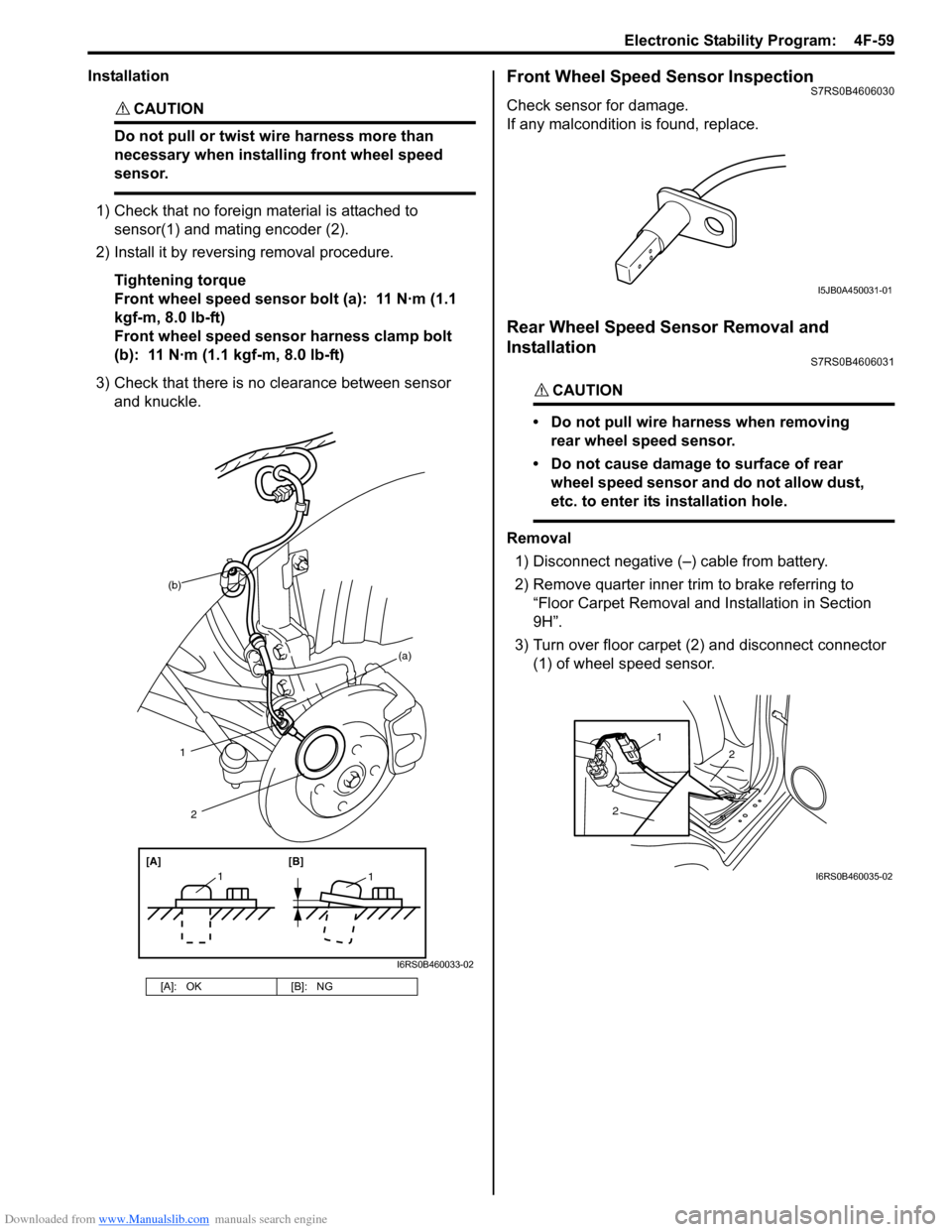
Installation
CAUTION!
Do not pull or twist wire harness more than
necessary when installing front wheel speed
sensor.
1) Check that no foreign material is attached to sensor(1) and mating encoder (2).
2) Install it by reversing removal procedure.
Tightening torque
Front wheel speed sensor bolt (a): 11 N·m (1.1
kgf-m, 8.0 lb-ft)
Front wheel speed sensor harness clamp bolt
(b): 11 N·m (1.1 kgf-m, 8.0 lb-ft)
3) Check that there is no clearance between sensor and knuckle.
Front Wheel Speed Sensor InspectionS7RS0B4606030
Check sensor for damage.
If any malcondition is found, replace.
Rear Wheel Speed Sensor Removal and
Installation
S7RS0B4606031
CAUTION!
• Do not pull wire harness when removing rear wheel speed sensor.
• Do not cause damage to surface of rear wheel speed sensor and do not allow dust,
etc. to enter its installation hole.
Removal
1) Disconnect negative (–) cable from battery.
2) Remove quarter inner trim to brake referring to
“Floor Carpet Removal and Installation in Section
9H”.
3) Turn over floor carpet (2) and disconnect connector (1) of wheel speed sensor.
[A]: OK [B]: NG
(b)
1
[A][B]
11
2
(a)
I6RS0B460033-02
I5JB0A450031-01
2
2
1
I6RS0B460035-02
Page 634 of 1496
Downloaded from www.Manualslib.com manuals search engine 4F-60 Electronic Stability Program:
4) Hoist vehicle and remove wheel.
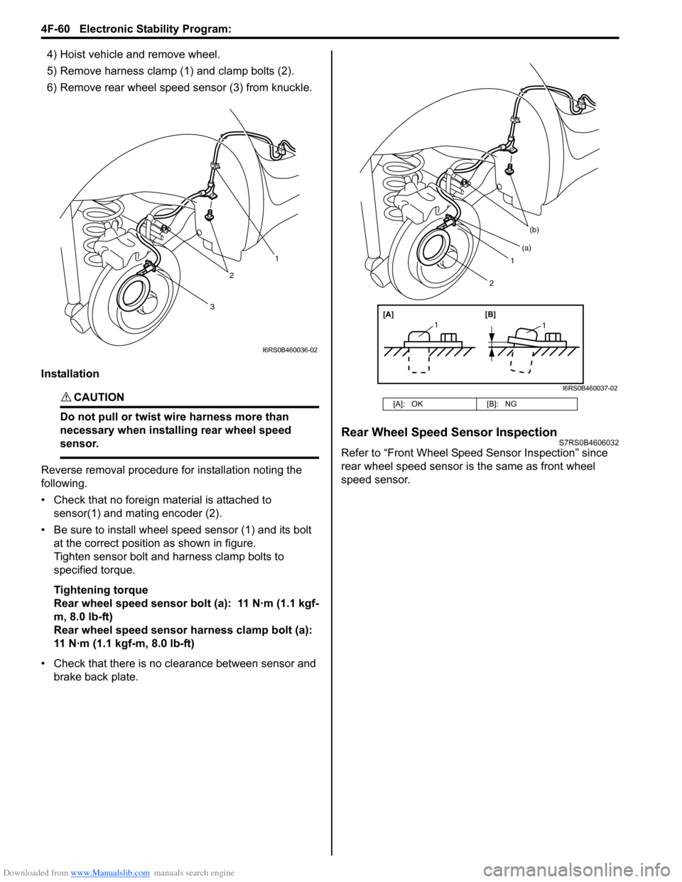
5) Remove harness clamp (1) and clamp bolts (2).
6) Remove rear wheel speed sensor (3) from knuckle.
Installation
CAUTION!
Do not pull or twist wi re harness more than
necessary when installing rear wheel speed
sensor.
Reverse removal procedure for installation noting the
following.
• Check that no foreign material is attached to sensor(1) and mating encoder (2).
• Be sure to install wheel speed sensor (1) and its bolt at the correct position as shown in figure.
Tighten sensor bolt and harness clamp bolts to
specified torque.
Tightening torque
Rear wheel speed sensor bolt (a): 11 N·m (1.1 kgf-
m, 8.0 lb-ft)
Rear wheel speed sensor harness clamp bolt (a):
11 N·m (1.1 kgf-m, 8.0 lb-ft)
• Check that there is no clearance between sensor and brake back plate.
Rear Wheel Speed Sensor InspectionS7RS0B4606032
Refer to “Front Wheel Speed Sensor Inspection” since
rear wheel speed sensor is the same as front wheel
speed sensor.
3
2
1
I6RS0B460036-02
[A]: OK [B]: NG
1
(b)
[A][B]
11
(a)
2
I6RS0B460037-02
Page 641 of 1496
Downloaded from www.Manualslib.com manuals search engine Table of Contents 5- i
5
Section 5
CONTENTS
Transmission / Transaxle
Precautions ................................................. 5-1
Precautions............................................................. 5-1
Precautions on Transmission / Transaxle ............. 5-1
Automatic Transmission/Transaxle ....... 5A-1
Precautions........................................................... 5A-1Precautions in Diagnosing Trouble ..................... 5A-1
Precautions for Disassembly and Reassembly ...................................................... 5A-1
General Description ............................................. 5A-3 A/T Description ................................................... 5A-3
Clutch / Brake / Planetary Gear Function of Automatic Transaxle ......................................... 5A-6
Table of Component Operation ........................... 5A-7
Brake Interlock System Construction .................. 5A-8
A/T Diagnosis General Description ..................... 5A-8
On-Board Diagnostic System Description ........... 5A-8
CAN Communication System Description........... 5A-9
Schematic and Routing Diagram ...................... 5A-10 Transmission Control Module (TCM) Wiring
Diagram .......................................................... 5A-10
Automatic Gear Shift Table ............................... 5A-12
Component Locatio n ......................................... 5A-13
Electronic Shift Cont rol System Components
Location .......................................................... 5A-13
Diagnostic Information and Procedures .......... 5A-15 A/T System Check ............................................ 5A-15
Visual Inspection ............................................... 5A-18
Malfunction Indicator Lamp (MIL) Check .......... 5A-18
Transmission Warning Ligh t Check .................. 5A-18
DTC Table ......................................................... 5A-19
DTC Check ....................................................... 5A-20
DTC Clearance ................................................. 5A-20
Fail-Safe Table ................ .................................. 5A-21
Scan Tool Data ................................................. 5A-23
A/T Basic Check ............................................... 5A-26
Road Test ......................................................... 5A-27
Manual Road Test ........... .................................. 5A-29
Engine Brake Test ............................................ 5A-30
Stall Test ........................................................... 5A-30
Time Lag Test ................................................... 5A-31
Line Pressure Test .......... .................................. 5A-32
“P” Range Test.................................................. 5A-33
A/T Symptom Diagnosis ..... .............................. 5A-34 No Gear Shift to 4th gear .................................. 5A-41
No Lock-Up Occurs ........................................... 5A-42
Transmission Warning Light Circuit Check –
Light Does Not Come “ON” at Ignition Switch
ON ................................................................... 5A-43
Transmission Warning Light Circuit Check – Light Remains “ON” at Ignition Switch ON ...... 5A-43
DTC P0602: Control Module Programming Error ................................................................ 5A-44
DTC P0705: Transmission Range Sensor Circuit Malfunction (PRNDL input) .................. 5A-44
DTC P0707: Transmission Range Sensor Circuit Low ...................................................... 5A-46
DTC P0712: Transmission Fluid Temperature Sensor “A” Circuit Low ... ................................. 5A-48
DTC P0713: Transmission Fluid Temperature Sensor “A” Circuit High .. ................................. 5A-49
DTC P0717: Input / Turbine Speed Sensor “A” Circuit Malfunction........................................... 5A-51
DTC P0722: Output Speed Sensor Circuit No Signal .............................................................. 5A-52
DTC P0787: Shift / Timing Solenoid Low .......... 5A-54
DTC P0788: Shift / Timing Solenoid High ......... 5A-56
DTC P0961: Pressure Control Solenoid “A”
Control Circuit Range / Performance .............. 5A-58
DTC P0962: Pressure Control Solenoid “A”
Control Circuit Low .......................................... 5A-60
DTC P0963: Pressure Control Solenoid “A”
Control Circuit High ......................................... 5A-62
DTC P0973 / P0976: Shift Solenoid “A” Control Circuit Low / Shift Solenoid “B”
Control Circuit Low .......................................... 5A-64
DTC P0974 / P0977: Shift Solenoid “A” / Shift Solenoid “B” Control Circuit High .................... 5A-66
DTC P1702: Internal Co ntrol Module Memory
Check Sum Error............................................. 5A-68
DTC P1703: Can Invalid Data - TCM ................ 5A-68
DTC P1723: Range Select Switch Malfunction ...................................................... 5A-69
DTC P1774: CAN Communication Bus Off ....... 5A-71
DTC P1777: TCM Lost Communication with ECM (Reception Error).................................... 5A-73
DTC P1778: TCM Lost Communication with BCM (Reception Error).................................... 5A-74
Page 659 of 1496
Downloaded from www.Manualslib.com manuals search engine Automatic Transmission/Transaxle: 5A-15
Diagnostic Information and Procedures
A/T System CheckS7RS0B5104001
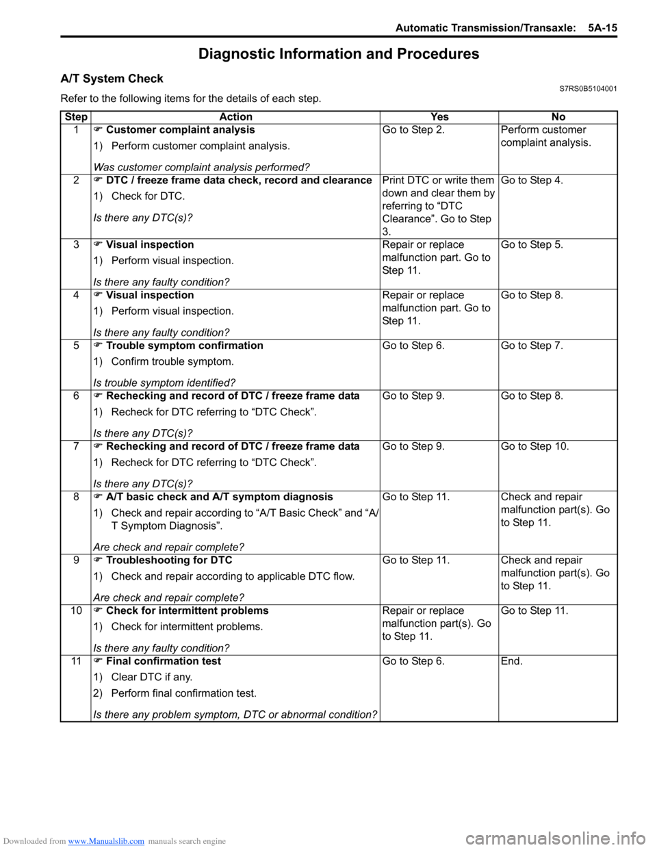
Refer to the following items for the details of each step.Step Action Yes No 1 �) Customer complaint analysis
1) Perform customer complaint analysis.
Was customer complaint analysis performed? Go to Step 2. Perform customer
complaint analysis.
2 �) DTC / freeze frame data check, record and clearance
1) Check for DTC.
Is there any DTC(s)? Print DTC or write them
down and clear them by
referring to “DTC
Clearance”. Go to Step
3.Go to Step 4.
3 �) Visual inspection
1) Perform visual inspection.
Is there any faulty condition? Repair or replace
malfunction part. Go to
St ep 11 .
Go to Step 5.
4 �) Visual inspection
1) Perform visual inspection.
Is there any faulty condition? Repair or replace
malfunction part. Go to
St ep 11 .
Go to Step 8.
5 �) Trouble symptom confirmation
1) Confirm trouble symptom.
Is trouble symptom identified? Go to Step 6.
Go to Step 7.
6 �) Rechecking and record of DTC / freeze frame data
1) Recheck for DTC referring to “DTC Check”.
Is there any DTC(s)? Go to Step 9.
Go to Step 8.
7 �) Rechecking and record of DTC / freeze frame data
1) Recheck for DTC referring to “DTC Check”.
Is there any DTC(s)? Go to Step 9.
Go to Step 10.
8 �) A/T basic check and A/T symptom diagnosis
1) Check and repair according to “A/T Basic Check” and “A/
T Symptom Diagnosis”.
Are check and repair complete? Go to Step 11. Check and repair
malfunction part(s). Go
to Step 11.
9 �) Troubleshooting for DTC
1) Check and repair according to applicable DTC flow.
Are check and repair complete? Go to Step 11. Check and repair
malfunction part(s). Go
to Step 11.
10 �) Check for intermittent problems
1) Check for interm ittent problems.
Is there any faulty condition? Repair or replace
malfunction part(s). Go
to Step 11.
Go to Step 11.
11 �) Final confirmation test
1) Clear DTC if any.
2) Perform final confirmation test.
Is there any problem symptom, DTC or abnormal condition? Go to Step 6.
End.
Page 661 of 1496
Downloaded from www.Manualslib.com manuals search engine Automatic Transmission/Transaxle: 5A-17
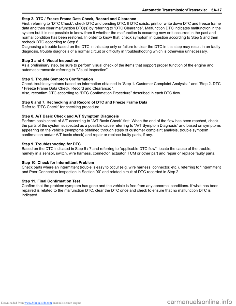
Step 2. DTC / Freeze Frame Data Check, Record and Clearance
First, referring to “DTC Check”, check DTC and pending DTC. If DTC exists, print or write down DTC and freeze frame
data and then clear malfunction DTC(s) by referring to “DTC Clearance”. Malfunction DTC indicates malfunction in the
system but it is not possible to know from it whether the malfunction is occurring now or it occurred in the past and
normal condition has been restored. In order to know that, check symptom in question according to Step 5 and then
recheck DTC according to Step 6.
Diagnosing a trouble based on the DTC in this step only or fa ilure to clear the DTC in this step may result in an faulty
diagnosis, trouble diagnosis of a normal circuit or difficulty in troubleshooting which is otherwise unnecessary.
Step 3 and 4. Visual Inspection
As a preliminary step, be sure to perform visual check of the items that support proper function of the engine and
automatic transaxle referring to “Visual Inspection”.
Step 5. Trouble Symptom Confirmation
Check trouble symptoms based on information obtained in “Step 1. Customer Complaint Analysis: ” and “Step 2. DTC
/ Freeze Frame Data Check, Record and Clearance: ”.
Also, reconfirm DTC according to “DTC Confirmation Procedure” described in each DTC flow.
Step 6 and 7. Rechecking and Record of DTC and Freeze Frame Data
Refer to “DTC Check” for checking procedure.
Step 8. A/T Basic Check and A/T Symptom Diagnosis
Perform basic check of A/T according to “A/T Basic Check” first. When the end of the flow has been reached, check
the parts of the system suspected as a possible cause referring to “A/T Symptom Diagnosis” and based on symptoms
appearing on the vehicle (symptoms obtained through step s of customer complaint analysis, trouble symptom
confirmation and/or A/T basic check) and re pair or replace faulty parts, if any.
Step 9. Troubleshooting for DTC
Based on the DTC indicated in Step 6 / 7 and referring to “a pplicable DTC flow”, locate the cause of the trouble,
namely in a sensor, switch, wire harness, connector, actuator, TCM or other part and repair or replace faulty parts.
Step 10. Check for Intermittent Problem
Check parts where an intermittent trouble is easy to occur (e.g . wire harness, connector, etc.), referring to “Intermittent
and Poor Connection Inspection in Section 00” and related circuit of DTC recorded in Step 2.
Step 11. Final Confirmation Test
Confirm that the problem symptom has gone and the vehicl e is free from any abnormal conditions. If what has been
repaired is related to the malfunction DTC, clear the DTC once and check to ensure that no malfunction DTC is
indicated.
Page 664 of 1496
Downloaded from www.Manualslib.com manuals search engine 5A-20 Automatic Transmission/Transaxle:
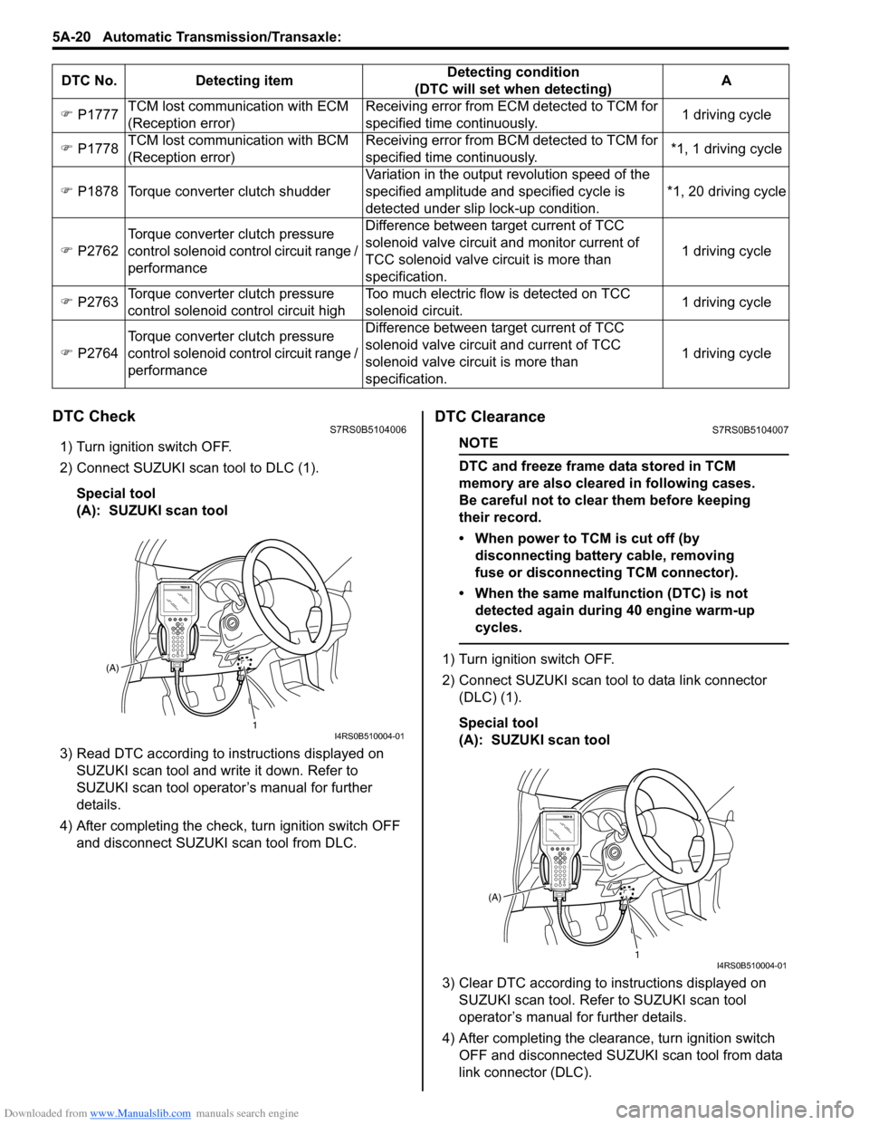
DTC CheckS7RS0B5104006
1) Turn ignition switch OFF.
2) Connect SUZUKI scan tool to DLC (1).
Special tool
(A): SUZUKI scan tool
3) Read DTC according to instructions displayed on SUZUKI scan tool and wr ite it down. Refer to
SUZUKI scan tool operator’s manual for further
details.
4) After completing the check, turn ignition switch OFF
and disconnect SUZUKI scan tool from DLC.
DTC ClearanceS7RS0B5104007
NOTE
DTC and freeze frame data stored in TCM
memory are also cleared in following cases.
Be careful not to clear them before keeping
their record.
• When power to TCM is cut off (by disconnecting battery cable, removing
fuse or disconnecting TCM connector).
• When the same malfunction (DTC) is not detected again during 40 engine warm-up
cycles.
1) Turn ignition switch OFF.
2) Connect SUZUKI scan tool to data link connector (DLC) (1).
Special tool
(A): SUZUKI scan tool
3) Clear DTC according to instructions displayed on SUZUKI scan tool. Refer to SUZUKI scan tool
operator’s manual for further details.
4) After completing the clearance, turn ignition switch OFF and disconnected SUZUKI scan tool from data
link connector (DLC).
�)
P1777 TCM lost communication with ECM
(Reception error) Receiving error from ECM detected to TCM for
specified time continuously.
1 driving cycle
�) P1778 TCM lost communication with BCM
(Reception error) Receiving error from BCM detected to TCM for
specified time continuously.
*1, 1 driving cycle
�) P1878 Torque converter clutch shudder Variation in the output revolution speed of the
specified amplitude and specified cycle is
detected under slip lock-up condition. *1, 20 driving cycle
�) P2762 Torque converter clutch pressure
control solenoid control circuit range /
performance Difference between target current of TCC
solenoid valve circuit and monitor current of
TCC solenoid valve ci
rcuit is more than
specification. 1 driving cycle
�) P2763 Torque converter clutch pressure
control solenoid control circuit high Too much electric flow is detected on TCC
solenoid circuit.
1 driving cycle
�) P2764 Torque converter clutch pressure
control solenoid control circuit range /
performance Difference between target current of TCC
solenoid valve circuit and current of TCC
solenoid valve circuit is more than
specification.
1 driving cycle
DTC No. Detecting item
Detecting condition
(DTC will set when detecting) A
1
(A)I4RS0B510004-01
1
(A)I4RS0B510004-01
Page 688 of 1496
Downloaded from www.Manualslib.com manuals search engine 5A-44 Automatic Transmission/Transaxle:
DTC P0602: Control Module Programming ErrorS7RS0B5104048
System Description
Internal control module is installed in ECM.
DTC Detecting Condition and Trouble Area
DTC Confirmation Procedure 1) Connect scan tool to DLC with ignition switch turned OFF.
2) Clear DTC, pending DTC and freeze frame data by using scan tool.
3) Start engine and run it at idle if possible.
4) Check DTC.
DTC Troubleshooting
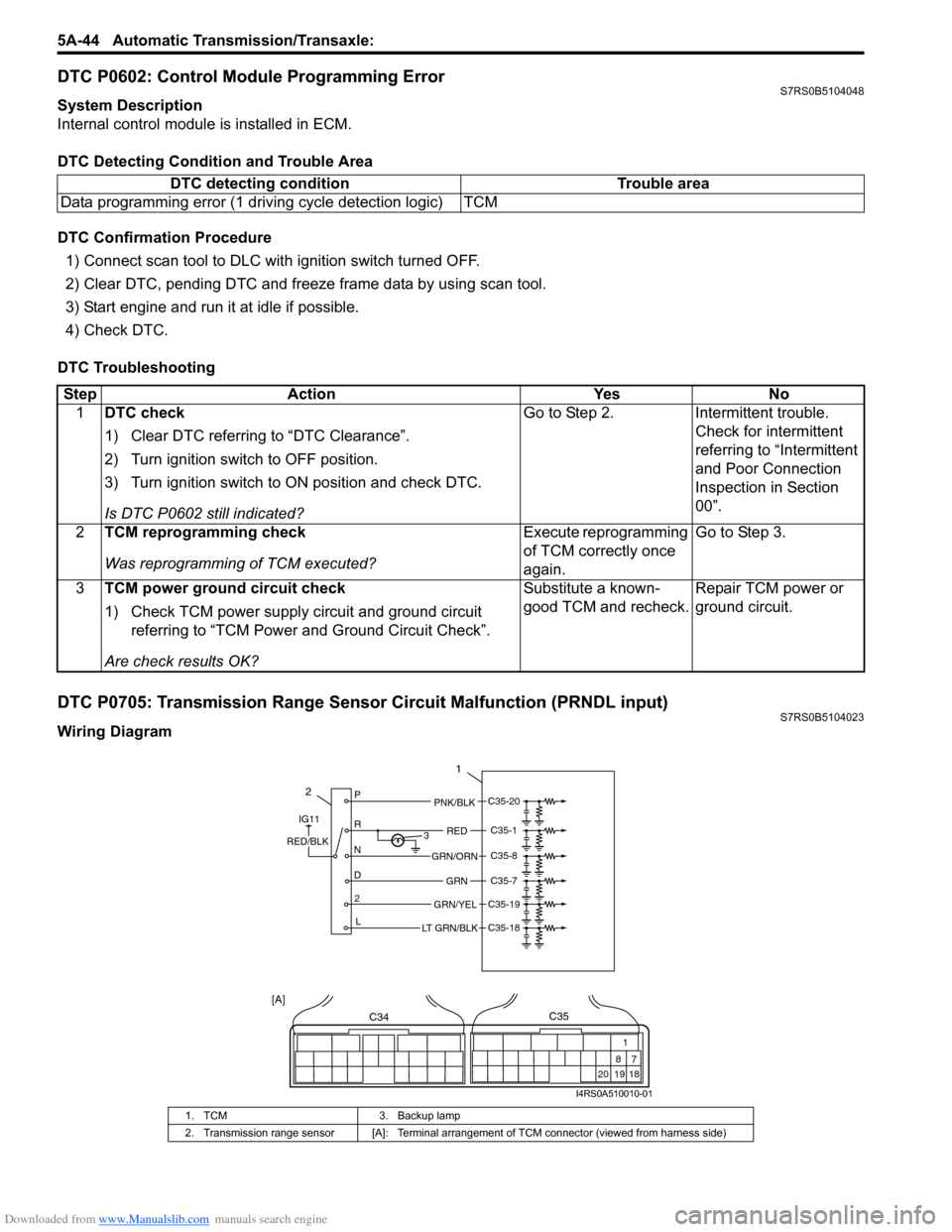
DTC P0705: Transmission Range Sensor Circuit Malfunction (PRNDL input)S7RS0B5104023
Wiring DiagramDTC detecting condition Trouble area
Data programming error (1 driving cycle detection logic) TCM
Step Action YesNo
1 DTC check
1) Clear DTC referring to “DTC Clearance”.
2) Turn ignition switch to OFF position.
3) Turn ignition switch to ON position and check DTC.
Is DTC P0602 still indicated? Go to Step 2.
Intermittent trouble.
Check for intermittent
referring to “Intermittent
and Poor Connection
Inspection in Section
00”.
2 TCM reprogramming check
Was reprogramming of TCM executed? Execute reprogramming
of TCM correctly once
again.Go to Step 3.
3 TCM power ground circuit check
1) Check TCM power supply circuit and ground circuit
referring to “TCM Power and Ground Circuit Check”.
Are check results OK? Substitute a known-
good TCM and recheck.
Repair TCM power or
ground circuit.
1. TCM
3. Backup lamp
2. Transmission range sensor [A]: Terminal arrangem ent of TCM connector (viewed from harness side)
2P
R
N
D 2 L 3
1
PNK/BLK
RED
GRN
GRN/ORN
GRN/YEL
IG11
RED/BLK
LT GRN/BLK
C35-20
C35-1
C35-8
C35-7
C35-19
C35-18
C34
20 19
87
18
1
C35
[A]
I4RS0A510010-01
Page 766 of 1496
Downloaded from www.Manualslib.com manuals search engine 5A-122 Automatic Transmission/Transaxle:
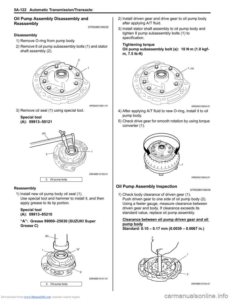
Oil Pump Assembly Disassembly and
Reassembly
S7RS0B5106035
Disassembly1) Remove O-ring from pump body.
2) Remove 8 oil pump subassembly bolts (1) and stator shaft assembly (2).
3) Remove oil seal (1) using special tool. Special tool
(A): 09913–50121
Reassembly 1) Install new oil pump body oil seal (1). Use special tool and hammer to install it, and then
apply grease to its lip portion.
Special tool
(A): 09913–85210
“A”: Grease 99000–25030 (SUZUKI Super
Grease C) 2) Install driven gear and drive gear to oil pump body
after applying A/T fluid.
3) Install stator shaft assembly to oil pump body and tighten 8 pump subassembly bolts (1) to
specification.
Tightening torque
Oil pump subassembly bolt (a): 10 N·m (1.0 kgf-
m, 7.5 lb-ft)
4) After applying A/T fluid to new O-ring, install it to oil pump body.
5) Check drive gear for smooth rotation by using torque converter (1).
Oil Pump Assembly InspectionS7RS0B5106036
1) Check body clearance of driven gear (1).Push driven gear to one side of oil pump body (2).
Using a feeler gauge, m easure clearance between
driven gear and body. If clearance exceeds its
standard value, replace oil pump assembly.
Clearance between oil pump driven gear and oil
pump body
Standard: 0.10 – 0.17 mm (0.0039 – 0.0067 in.)
2. Oil pump body
2. Oil pump body
2 1
I4RS0A510041-01
I2RH0B510150-01
I2RH0B510151-01
1, (a)
I4RS0A510042-01
1
I4RS0A510043-01
I2RH0B510154-01
Page 767 of 1496
Downloaded from www.Manualslib.com manuals search engine Automatic Transmission/Transaxle: 5A-123
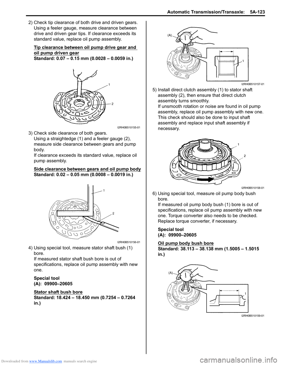
2) Check tip clearance of both drive and driven gears.Using a feeler gauge, m easure clearance between
drive and driven gear tips. If clearance exceeds its
standard value, replace oil pump assembly.
Tip clearance between oil pump drive gear and
oil pump driven gear
Standard: 0.07 – 0.15 mm (0.0028 – 0.0059 in.)
3) Check side clearance of both gears. Using a straightedge (1) and a feeler gauge (2),
measure side clearance between gears and pump
body.
If clearance exceeds its standard value, replace oil
pump assembly.
Side clearance between gears and oil pump body
Standard: 0.02 – 0.05 mm (0.0008 – 0.0019 in.)
4) Using special tool, measure stator shaft bush (1) bore.
If measured stator shaft bush bore is out of
specifications, replace oil pump assembly with new
one.
Special tool
(A): 09900–20605
Stator shaft bush bore
Standard: 18.424 – 18.450 mm (0.7254 – 0.7264
in.) 5) Install direct clutch asse
mbly (1) to stator shaft
assembly (2), then ensure that direct clutch
assembly turns smoothly.
If unsmooth rotation or noise are found in oil pump
assembly, replace oil pump assembly with new one.
This check should also be done to input shaft
assembly and replace input shaft assembly if
necessary.
6) Using special tool, measure oil pump body bush bore.
If measured oil pump body bush (1) bore is out of
specifications, replace o il pump assembly with new
one. Torque converter also needs to be checked.
Replace torque converter, if necessary.
Special tool
(A): 09900–20605
Oil pump body bush bore
Standard: 38.113 – 38.138 mm (1.5005 – 1.5015
in.)
I2RH0B510155-01
I2RH0B510156-01
I2RH0B510157-01
I2RH0B510158-01
I2RH0B510159-01
Page 833 of 1496
Downloaded from www.Manualslib.com manuals search engine Manual Transmission/Transaxle: 5B-19
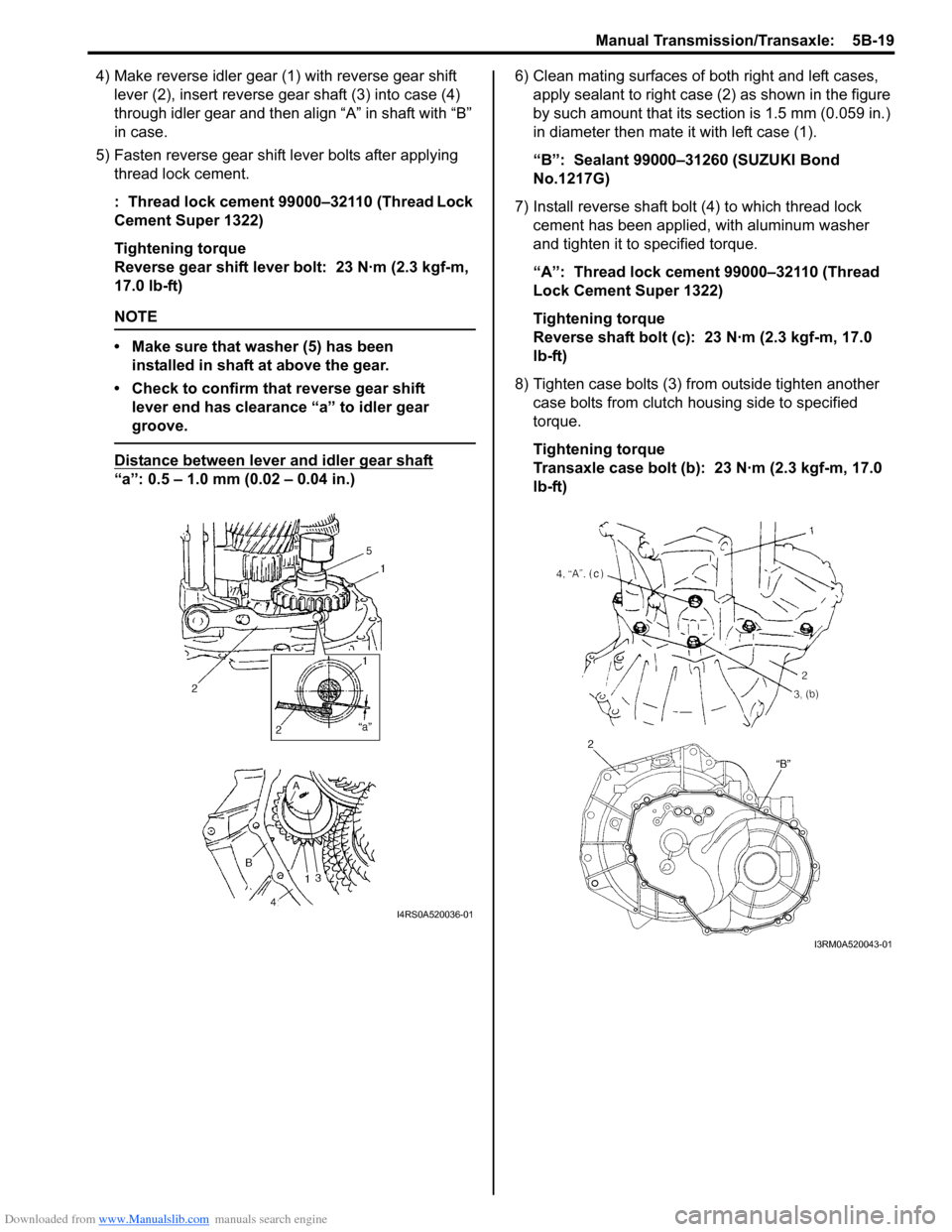
4) Make reverse idler gear (1) with reverse gear shift lever (2), insert reverse gear shaft (3) into case (4)
through idler gear and then align “A” in shaft with “B”
in case.
5) Fasten reverse gear shift lever bolts after applying thread lock cement.
: Thread lock cement 99000–32110 (Thread Lock
Cement Super 1322)
Tightening torque
Reverse gear shift lever bolt: 23 N·m (2.3 kgf-m,
17.0 lb-ft)
NOTE
• Make sure that washer (5) has been installed in shaft at above the gear.
• Check to confirm that reverse gear shift lever end has clearance “a” to idler gear
groove.
Distance between lever and idler gear shaft
“a”: 0.5 – 1.0 mm (0.02 – 0.04 in.) 6) Clean mating surfaces of both right and left cases,
apply sealant to right case (2) as shown in the figure
by such amount that its section is 1.5 mm (0.059 in.)
in diameter then mate it with left case (1).
“B”: Sealant 99000–31260 (SUZUKI Bond
No.1217G)
7) Install reverse shaft bolt (4) to which thread lock cement has been applied, with aluminum washer
and tighten it to specified torque.
“A”: Thread lock cement 99000–32110 (Thread
Lock Cement Super 1322)
Tightening torque
Reverse shaft bolt (c): 23 N·m (2.3 kgf-m, 17.0
lb-ft)
8) Tighten case bolts (3) from outside tighten another case bolts from clutch housing side to specified
torque.
Tightening torque
Transaxle case bolt (b): 23 N·m (2.3 kgf-m, 17.0
lb-ft)
I4RS0A520036-01
I3RM0A520043-01