clearance SUZUKI SWIFT 2006 2.G Service Manual Online
[x] Cancel search | Manufacturer: SUZUKI, Model Year: 2006, Model line: SWIFT, Model: SUZUKI SWIFT 2006 2.GPages: 1496, PDF Size: 34.44 MB
Page 891 of 1496
Downloaded from www.Manualslib.com manuals search engine Power Assisted Steering System: 6C-9
3) Start engine.
4) Read DTC according to the instructions displayed on
SUZUKI scan tool. For further details, refer to
operator’s manual for SUZUKI scan tool.
NOTE
• If communication between SUZUKI scan tool and the vehicle can not be
established, perform “Serial Data Link
Circuit Check”.
• DTC C1122 (engine speed signal failure) is indicated when ignition switch is at ON
position and engine is not running, but it
means there is nothing abnormal if
indication changes to a normal one when
engine is started.
5) After completing the check, turn ignition switch to
OFF position and disconnect SUZUKI scan tool from
DLC.
DTC ClearanceS7RS0B6304004
1) Turn ignition switch to OFF position.
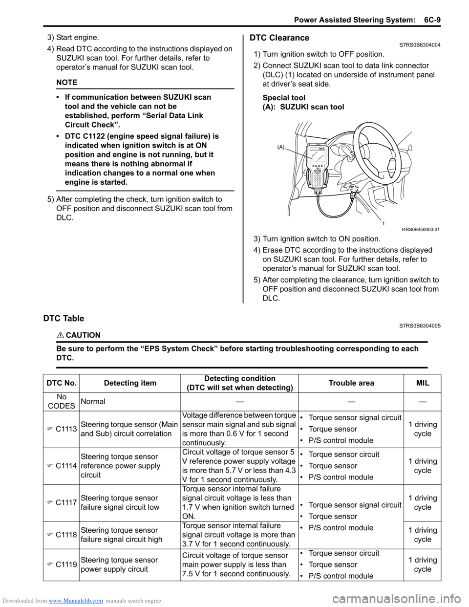
2) Connect SUZUKI scan tool to data link connector (DLC) (1) located on underside of instrument panel
at driver’s seat side.
Special tool
(A): SUZUKI scan tool
3) Turn ignition switch to ON position.
4) Erase DTC according to the instructions displayed on SUZUKI scan tool. For further details, refer to
operator’s manual for SUZUKI scan tool.
5) After completing the clearance, turn ignition switch to OFF position and disconnect SUZUKI scan tool from
DLC.
DTC TableS7RS0B6304005
CAUTION!
Be sure to perform the “EPS Syst em Check” before starting troubleshooting corresponding to each
DTC.
(A)
1
I4RS0B450003-01
DTC No. Detecting item Detecting condition
(DTC will set when detecting) Trouble area MIL
No
CODES Normal — — —
�) C1113 Steering torque sensor (Main
and Sub) circuit correlation Voltage difference between torque
sensor main signal and sub signal
is more than 0.6 V for 1 second
continuously. • Torque sensor signal circuit
• Torque sensor
• P/S control module
1 driving
cycle
�) C1114 Steering torque sensor
reference power supply
circuit Circuit voltage of torque sensor 5
V reference power supply voltage
is more than 5.7 V or less than 4.3
V for 1 second continuously. • Torque sensor circuit
• Torque sensor
• P/S control module
1 driving
cycle
�) C1117 Steering torque sensor
failure signal circuit low Torque sensor internal failure
signal circuit voltage is less than
1.7 V when ignition switch turned
ON.
• Torque sensor signal circuit
• Torque sensor
• P/S control module1 driving
cycle
�) C1118 Steering torque sensor
failure signal circuit high Torque sensor internal failure
signal circuit voltage is more than
3.7 V for 1 second continuously. 1 driving
cycle
�) C1119 Steering torque sensor
power supply circuit Circuit voltage of torque sensor
main power supply
is less than
7.5 V for 1 second continuously. • Torque sensor circuit
• Torque sensor
• P/S control module
1 driving
cycle
Page 911 of 1496
Downloaded from www.Manualslib.com manuals search engine Power Assisted Steering System: 6C-29
DTC TroubleshootingStep Action Yes No 1 Was “EPS System Check” performed? Go to Step 2. Go to “EPS System
Check”.
2 DTC check
1) Clear DTC(s) referring to “DTC Clearance”.
2) Run engine at idle speed.
3) Check if any DTC is detecte d referring to “DTC Check”.
Is DTC C1122 still detected? Go to Step 3. Check intermittent
trouble referring to
“Intermittent and Poor
Connection Inspection
in Section 00”.
3 DTC check
1) Check ECM for DTC referring to “DTC Check in Section
1A”.
Is there any DTC related to engine speed? Go to applicable DTC
diag. flow.
Go to Step 4.
4 Engine speed signal circuit check
1) With ignition switch turned OFF, disconnect P/S control
module connector.
2) Check P/S control module connector for proper connection.
3) If OK, turn ON ignition switch, measure voltage between “E52-12” wire terminal of P/S control module connector
and vehicle body ground.
Is voltage 10 – 14 V? Go to Step 6.
Go to Step 5.
5 1) With ignition switch turned OFF, disconnect ECM connector.
2) Check for proper connection to the P/S control module and ECM at each “Engine speed signal circuit” terminal.
3) If connections are OK, chec k that “Engine speed signal
circuit” is as following.
• Insulation resistance of “Engine speed signal circuit” wire is infinity between its terminal and other terminals
at ECM and P/S control module connector.
• Wiring resistance of “Engine speed signal circuit” terminal are less than 1 Ω.
• Insulation resistance of “Engine speed signal circuit” between its terminal and vehicle body ground is
infinity.
• Circuit voltage between “Engine speed signal circuit” and ground circuit is 0 – 1 V with ignition switch turned
ON.
Is circuit in good condition? Go to Step 6.
Repair engine speed
signal circuit.
6 ECM voltage check
1) Connect P/S control mo dule and ECM connectors.
2) Check ECM for engine speed signal and vehicle speed signal output voltage to P/S control module referring to
“Inspection of ECM and Its Circuits in Section 1A”.
Is check result in good condition? Substitute a known-
good P/S control
module and recheck.
Substitute a known-
good ECM and recheck.
Page 934 of 1496

Downloaded from www.Manualslib.com manuals search engine 7-ii Table of Contents
Recommended Service Material ....................... 7B-33
Special Tool ...................................................... 7B-33
Automatic Type .................... .................................7B-34
Precautions.........................................................7B-34 A/C System Caution .......................................... 7B-34
Precautions in Diagnosing Trouble ................... 7B-34
Precautions on Servicing A/C System .............. 7B-34
General Description .......... .................................7B-34
Auto A/C System Descript ion ............................ 7B-34
HVAC Control Module Operation Description ... 7B-36
Refrigerant Type Identifica tion .......................... 7B-36
Sub-Cool A/C System Description .................... 7B-36
A/C Operation Description ................................ 7B-36
On-Board Diagnostic System Description ......... 7B-37
Schematic and Routing Diagram ......................7B-37 Major Components of A/C System .................... 7B-37
A/C System Wiring Diagra m ............................. 7B-38
Diagnostic Information and Procedures ..........7B-39 A/C System Symptom Diagnosis ...................... 7B-39
Abnormal Noise Sympto m Diagnosis of A/C
System ............................................................ 7B-42
DTC Check........................................................ 7B-42
DTC Clearance ................................................. 7B-43
DTC Table ......................................................... 7B-44
Fail-Safe Table ................. ................................. 7B-45
Scan Tool Data ................................................. 7B-46
Air Conditioning System Check......................... 7B-47
Visual Inspection ............................................... 7B-49
DTC B1502: Inside Air Temperature Sensor and/or Its Circuit Malfunction .......................... 7B-49
DTC B1503: A/C Evaporator Air Temperature Sensor and/or Its Circuit Malfunction .............. 7B-50
DTC B1504: Sunload Sensor and/or Its Circuit Malfunction ......... ................................. 7B-52
DTC B1511: Temperature Control Actuator (Position Sensor) and/or Its Circuit
Malfunction ...................................................... 7B-53
DTC B1512: Air flow Control Actuator (Position Sensor) and/or Its Circuit
Malfunction ...................................................... 7B-55
DTC B1513: Temperature Control Actuator and/or Its Circuit Malfunction .......................... 7B-57
DTC B1514: Air Flow Co ntrol Actuator and/or
Its Circuit Malfunction ...................................... 7B-60
DTC B1541: HVAC Control Module Back-Up Power Supply Malfunction .............................. 7B-62
DTC B1546: A/C Refrigerant Pressure Malfunction ...................................................... 7B-63
DTC B1551: Serial Communication Circuit Malfunction ...................................................... 7B-63
DTC B1552: Serial Communication Signal Malfunction ...................................................... 7B-64
DTC B1553: CAN Communication Signal Malfunction ...................................................... 7B-65
DTC B1557: Vehicle Speed Sensor Signal Malfunction ...................................................... 7B-65
DTC B1561: Engine Coolant Temperature Sensor Signal Malfunctio n .............................. 7B-66 DTC B1562: Outside Air Temperature Sensor
Signal Malfunction ........................................... 7B-66
DTC B1563: A/C Refr igerant Pressure
Sensor Signal Malfunction .............................. 7B-66
Inspection of HVAC Control Module and Its Circuit .............................................................. 7B-67
A/C System Performance Inspection ................ 7B-70
A/C System Inspection at ECM ......................... 7B-70
Repair Instructions ............ ................................7B-71
Operation Procedure for Refrigerant Charge .... 7B-71
HVAC Unit Components ................................... 7B-72
HVAC Unit Removal and In stallation ................ 7B-73
Temperature Control Actuator Removal and Installation ....................................................... 7B-73
Temperature Control Actuat or Inspection ......... 7B-73
Air Flow Control Actuator Removal and Installation ....................................................... 7B-74
Air Flow Control Actuator Inspection ................. 7B-74
Air Intake Control Actuator Removal and Installation ....................................................... 7B-75
Air Intake Control Actuator Inspection............... 7B-75
Actuator Linkage Inspection .............................. 7B-76
Blower Motor Controller Removal and Installation ....................................................... 7B-76
Blower Motor Controller Inspection ................... 7B-76
HVAC Control Module Removal and Installation ....................................................... 7B-77
Sunload Sensor Removal and Installation ........ 7B-77
Sunload Sensor Inspection ............................... 7B-77
Outside Air Temperature Sensor Removal and Installation ................................................ 7B-77
Outside Air Temperature Sensor Inspection ..... 7B-77
Inside Air Temperature Sensor Removal and Installation ....................................................... 7B-78
Inside Air Temperature Sens or Inspection ........ 7B-78
Condenser Assembly On-Vehicle Inspection .... 7B-78
Condenser Assembly Removal and Installation ....................................................... 7B-78
Receiver/Dryer Removal and Installation .......... 7B-78
Evaporator Inspection ....................................... 7B-78
Evaporator Temperature Sensor Removal and Installation ................................................ 7B-78
Evaporator Temperature Se nsor Inspection ..... 7B-78
Expansion Valve Removal an d Installation ....... 7B-78
Expansion Valve Inspection .............................. 7B-78
A/C Refrigerant Pressure Sensor and Its Circuit Inspection............................................. 7B-78
A/C Refrigerant Pressu re Sensor Removal
and Installation ................................................ 7B-78
Compressor Relay Inspection .
.......................... 7B-78
Compressor Drive Belt Inspection and Adjustment ...................................................... 7B-78
Compressor Drive Belt Removal and Installation ....................................................... 7B-79
Compressor Assembly Removal and Installation ....................................................... 7B-79
Compressor Assembly Components................. 7B-79
Magnet Clutch Removal and Installation........... 7B-79
Magnet Clutch Inspection.................................. 7B-79
Relief Valve Inspection...................................... 7B-79
Page 957 of 1496
Downloaded from www.Manualslib.com manuals search engine Air Conditioning System: Manual Type 7B-9
Abnormal Noise Symptom Diagnosis of A/C SystemS7RS0B7214002
Abnormal Noise from Compressor
Abnormal Noise from Magnetic Clutch
Abnormal Noise from Tubing
Abnormal Noise from Condenser Assembly
Abnormal Noise from Crankshaft PulleyInsufficient airflow of
cooled air
A/C evaporator clogged or frosted
Check A/C evaporator and evaporator
thermistor (evaporator temperature sensor)
referring to “Evaporator Inspection” and
“Evaporator Thermistor (Evaporator
Temperature Sensor) Inspection”.
Air leaking from HVAC unit or air duct Repair as necessary.
Blower motor faulty Check blower motor referring to “Blower Motor
Inspection in Section 7A”.
Wiring or grounding faulty Repair as necessary.
Condition Possible cause Correction / Reference Item
Condition
Possible cause Correction / Reference Item
During compressor
operation, a rumbling
noise is heard
proportional to engine
revolutions Inadequate clearance in scroll area
Replace compressor.
A loud noise is heard at a
certain rpm,
disproportionately to
engine revolution Loose or faulty compressor drive belt
Adjust drive belt tension or replace drive belt.
Loose compressor mounting bolts Retighten mounting bolts.
A loud rattle is heard at
low engine rpm Loose compressor clutch plate bolt
Retighten clutch plate bolt.
Replace compressor if it was operated in this
condition for a long time.
Condition Possible cause Correction / Reference Item
A rumbling noise is heard
when compressor is not
in operation Worn or damaged bearings
Replace magnet clutch assembly.
A chattering noise is
heard when compressor
is in operation Faulty magnet clutch clearance
(excessive clearance)
Adjust magnet clutch clearance.
Worn magnet clutch friction surface Replace magnet clutch assembly.
Compressor oil leaked from shaft seal,
contaminating the friction surface Replace compressor body assembly.
Condition
Possible cause Correction / Reference Item
A droning noise is heard
from inside of the vehicle,
but not particularly
noticeable in engine
compartment Faulty tubing clamps
Reposition clamps or increase the number of
clamps.
Resonance caused by pulsation from
variations in re frigerant pressure Attach a silencer to tubing, or modify its
position and length.
Condition
Possible cause Correction / Reference Item
Considerable vibration in
condenser assembly Resonance from condenser assembly
bracket and body Firmly insert a silenc
er between condenser
assembly bracket and body.
Condition Possible cause Correction / Reference Item
A large rattling noise is
heard at idle or sudden
acceleration Loosen crankshaft pulley bolt
Retighten bolt.
Page 968 of 1496
Downloaded from www.Manualslib.com manuals search engine 7B-20 Air Conditioning System: Manual Type
7) When refrigerant container (1) is emptied, use the following procedure to replace it with a new
refrigerant container.
a) Close low pressure valve.
b) Replace empty container with a refrigerant container which has been charged with
refrigerant. When using refrigerant container tap
valve (2), use the following procedure for
replacement.
i) Retract needle (3) and remove refrigerant container tap valve by loosening its plate nut
(4).
ii) Install the refrigerant container tap valve to a new refrigerant container.
c) Purge any air existing in center charging hose. When using refrigerant container tap valve, use
the following procedure to purge air.
i) Once fully tighten refrigerant container tap valve (1), and then loosen (open) plate nut
(2) slightly.
ii) Open low pressure side valve (3) of manifold
gauge set (4) a little.
iii) As soon as refrigerant comes out with a “hiss” through a clearance between
refrigerant container and tap valve, tighten
plate nut as well as low pressure side valve.
iv) Turn handle of tap valve clockwise so that its needle is screwed into the new container to
make a hole for refrigerant flow. 8) After the system has been charged with specified
amount (370 ± 20 g) of refrigerant or when low
pressure gauge (1) and high pressure gauge (2)
have indicated the following specified value, close
low pressure side valve (3) on manifold gauge set
(4).
Low side and high side pressure example
I2RH01720018-01
I2RH01720019-01
Gauges should read as follows when ambient
temperature is 30 °C (86 °F).
Pressure
on high pressure gauge 1590 – 1940 kPa
15.9 – 19.4 kg/cm
2
226 – 276 psi
Pressure
on low pressure gauge 270 – 430 kPa
2.7 – 4.3 kg/cm
2
38 – 61 psi
1
3 42
I4RS0A720016-01
Page 979 of 1496
Downloaded from www.Manualslib.com manuals search engine Air Conditioning System: Manual Type 7B-31
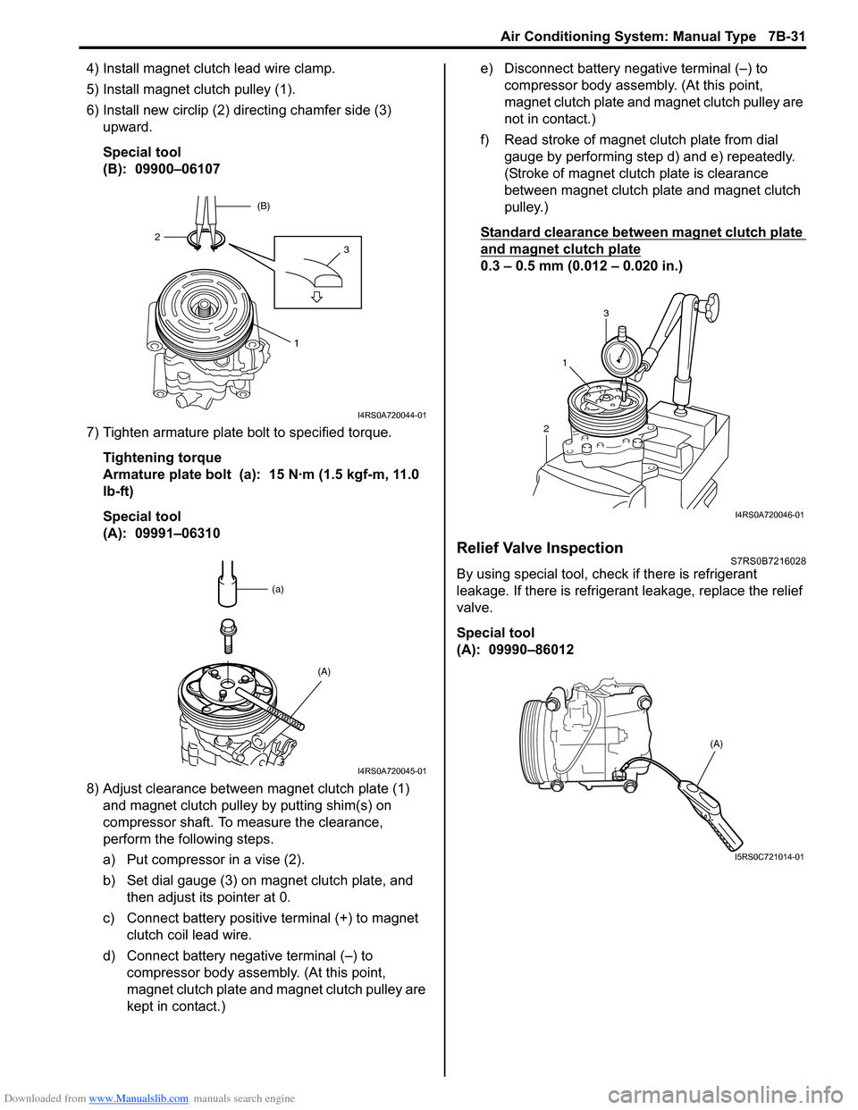
4) Install magnet clutch lead wire clamp.
5) Install magnet clutch pulley (1).
6) Install new circlip (2) directing chamfer side (3) upward.
Special tool
(B): 09900–06107
7) Tighten armature plate bolt to specified torque. Tightening torque
Armature plate bolt (a): 15 N·m (1.5 kgf-m, 11.0
lb-ft)
Special tool
(A): 09991–06310
8) Adjust clearance between magnet clutch plate (1) and magnet clutch pulley by putting shim(s) on
compressor shaft. To measure the clearance,
perform the following steps.
a) Put compressor in a vise (2).
b) Set dial gauge (3) on magnet clutch plate, and then adjust its pointer at 0.
c) Connect battery positive terminal (+) to magnet clutch coil lead wire.
d) Connect battery negative terminal (–) to compressor body assemb ly. (At this point,
magnet clutch plate and magnet clutch pulley are
kept in contact.) e) Disconnect battery negative terminal (–) to
compressor body assembly. (At this point,
magnet clutch plate and magnet clutch pulley are
not in contact.)
f) Read stroke of magnet clutch plate from dial gauge by performing step d) and e) repeatedly.
(Stroke of magnet clutch plate is clearance
between magnet clutch plate and magnet clutch
pulley.)
Standard clearance between magnet clutch plate
and magnet clutch plate
0.3 – 0.5 mm (0.012 – 0.020 in.)
Relief Valve InspectionS7RS0B7216028
By using special tool, chec k if there is refrigerant
leakage. If there is refrigerant leakage, replace the relief
valve.
Special tool
(A): 09990–86012
1
32 (B)
I4RS0A720044-01
(a)
(A)
I4RS0A720045-01
21
3
I4RS0A720046-01
(A)
I5RS0C721014-01
Page 991 of 1496
Downloaded from www.Manualslib.com manuals search engine Air Conditioning System: Automatic Type 7B-43
Not Using SUZUKI Scan Tool
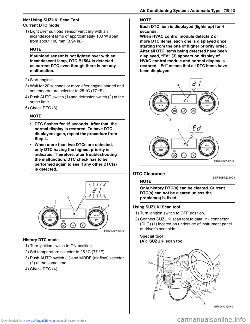
Current DTC mode1) Light over sunload sensor vertically with an incandescent lamp of approximately 100 W apart
from about 100 mm (3.94 in.).
NOTE
If sunload sensor is not lighted over with an
incandescent lamp, DTC B1504 is detected
as current DTC even though there is not any
malfunction.
2) Start engine.
3) Wait for 20 seconds or more after engine started and set temperature selector to 25 °C (77 °F).
4) Push AUTO switch (1) and defroster switch (2) at the same time.
5) Check DTC (3).
NOTE
• DTC flashes for 15 seconds. After that, the normal display is rest ored. To have DTC
displayed again, repeat the procedure from
Step 4.
• When more than two DTCs are detected, only DTC having the highest priority is
indicated. Therefore, after troubleshooting
the malfunction, DTC check has to be
performed again to see if any other DTC(s)
is detected.
History DTC mode
1) Turn ignition switch to ON position.
2) Set temperature selector to 25 °C (77 °F).
3) Push AUTO switch (1) and MODE (air flow) selector
(2) at the same time.
4) Check DTC (4).
NOTE
Each DTC item is displayed (lights up) for 4
seconds.
When HVAC control module detects 2 or
more DTC items, each one is displayed once
starting from the one of higher priority order.
After all DTC items being detected have been
displayed, “Ed” (3) appears on display of
HVAC control module and normal display is
restored. “Ed” means that all DTC items have
been displayed.
DTC ClearanceS7RS0B7224004
NOTE
Only history DTC(s) can be cleared. Current
DTC(s) can not be cleared unless the
problem(s) is fixed.
Using SUZUKI Scan tool
1) Turn ignition switch to OFF position.
2) Connect SUZUKI scan tool to data link connector (DLC) (1) located on underside of instrument panel
at driver’s seat side.
Special tool
(A): SUZUKI scan tool1
2
3
I5RS0A722006-02
1
2 34
I5RS0A722007-02
(A)
1
I5RS0A722005-01
Page 992 of 1496
Downloaded from www.Manualslib.com manuals search engine 7B-44 Air Conditioning System: Automatic Type
3) Light over sunload sensor vertically with an incandescent lamp approximately 100 W apart from
about 100 mm (3.94 in.).
NOTE
If sunload sensor is not lighted over with an
incandescent lamp, DTC B1504 is detected
as current DTC even though there is not any
malfunction.
4) Turn ignition switch to ON position.
5) Erase DTC according to instructions displayed on SUZUKI scan tool.
NOTE
To know how to use SUZUKI scan tool, refer
to operator’s manual for SUZUKI scan tool.
6) After completing the clearance, turn ignition switch to OFF position, and then di sconnect SUZUKI scan
tool from DLC.
Not Using SUZUKI Scan Tool 1) Turn ignition switch to ON position.
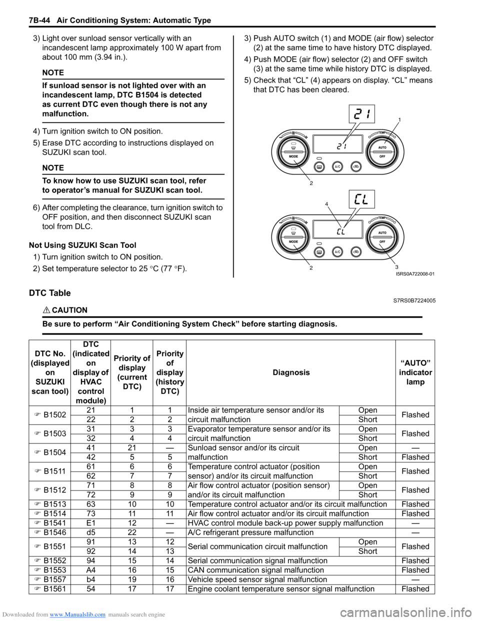
2) Set temperature selector to 25 °C (77 °F). 3) Push AUTO switch (1) and
MODE (air flow) selector
(2) at the same time to have history DTC displayed.
4) Push MODE (air flow) selector (2) and OFF switch (3) at the same time while history DTC is displayed.
5) Check that “CL” (4) appears on display. “CL” means that DTC has been cleared.
DTC TableS7RS0B7224005
CAUTION!
Be sure to perform “Air Conditioning Sy stem Check” before starting diagnosis.
1
2
3
2
4
I5RS0A722008-01
DTC No.
(displayed on
SUZUKI
scan tool) DTC
(indicated on
display of HVAC
control
module) Priority of
display
(current DTC) Priority
of
display
(history DTC) Diagnosis
“AUTO”
indicator lamp
�) B1502 21 1 1 Inside air temperature sensor and/or its
circuit malfunction Open
Flashed
22 2 2 Short
�) B1503 31 3 3 Evaporator temperature sensor and/or its
circuit malfunction Open
Flashed
32 4 4 Short
�) B1504 41 21 — Sunload sensor and/or its circuit
malfunction Open —
42 5 5 Short Flashed
�) B1511 61 6 6 Temperature control actuator (position
sensor) and/or its circuit malfunction Open
Flashed
62 7 7 Short
�) B1512 71 8 8 Air flow control actuator (position sensor)
and/or its circuit malfunction Open
Flashed
72 9 9 Short
�) B1513 63 10 10 Temperature control actuator and/or its circuit malfunction Flashed
�) B1514 73 11 11 Air flow control actuator and/or its circuit malfunction Flashed
�) B1541 E1 12 — HVAC control module back-up power supply malfunction —
�) B1546 d5 22 — A/C refrigerant pressure malfunction —
�) B1551 91 13 12
Serial communication circuit malfunction Open
Flashed
92 14 13 Short
�) B1552 94 15 14 Serial communication signal malfunction Flashed
�) B1553 A4 16 15 CAN communication signal malfunction Flashed
�) B1557 b4 19 16 Vehicle speed sensor signal malfunction —
�) B1561 54 17 17 Engine coolant temperature sensor signal malfunction Flashed
Page 1029 of 1496
Downloaded from www.Manualslib.com manuals search engine Table of Contents 8- i
8
Section 8
CONTENTS
Restraint
Precautions ................................................. 8-1
Precautions............................................................. 8-1
Precautions on Restraint ....................................... 8-1
Seat Belts .......... ............................... ........ 8A-1
Precautions........................................................... 8A-1
Precautions on Service a nd Diagnosis of Seat
Belt .................................................................... 8A-1
General Description ............................................. 8A-1 Seat Belt Construction ........................................ 8A-1
Diagnostic Information and Procedures ............ 8A-2 Repair and Inspection Required after Accident ............................................................ 8A-2
Repair Instructions .............................................. 8A-3 Front Seat Belt Components ............................... 8A-3
Front Seat Belt Removal and Installation ............ 8A-4
Front Seat Belt Inspection ................................... 8A-4
Rear Seat Belt Components ............................... 8A-6
Rear Seat Belt Removal and Installation ............ 8A-7
Rear Seat Belt Inspection ................................... 8A-7
Specifications ....................................................... 8A-7
Tightening Torque Specifications ........................ 8A-7
Air Bag System ............... ......................... 8B-1
Precautions........................................................... 8B-1
Precautions on Service and Diagnosis of Air Bag System....................................................... 8B-1
Precautions on Handling and Storage of Air Bag System Components . ................................ 8B-2
Precautions on Disposal of Air Bag and Seat
Belt Pretensioner .............................................. 8B-5
General Description ............................................. 8B-5 Air Bag System Construction .............................. 8B-5
Air Bag System Input / Output Table .................. 8B-6
Schematic and Routing Diagram ........................ 8B-7 Air Bag System Wiring Circuit Diagram .............. 8B-7
Component Locatio n ........................................... 8B-9
Air Bag System Components, Wiring and Connectors Location ......................................... 8B-9
Diagnostic Information and Procedures .......... 8B-10 Air Bag Diagnostic System Check .................... 8B-10
Air Bag Diagnostic System Check Flow ............ 8B-10
DTC Table ......................................................... 8B-11
DTC Check ....................................................... 8B-12 DTC Clearance ................................................. 8B-12
Scan Tool Data ................................................. 8B-13
“AIR BAG” Warning Right Comes ON Steady .. 8B-13
“AIR BAG” Warning Right Does Not Come
ON ................................................................... 8B-15
“AIR BAG” Warning Right Flashes .................... 8B-16
DTC B1013: SDM fault...................................... 8B-17
DTC B1014: “AIR BAG” Warning Right Circuit Failure ............................................................. 8B-17
DTC B1016: Power Source Voltage High ......... 8B-18
DTC B1017: Power Source Voltage Low .......... 8B-20
DTC B1021: Front Air Bag Module Deployed ... 8B-22
DTC B1024 / B1025: Side-Air Bag (Driver / Passenger) Deployed...................................... 8B-22
DTC B1026: Pretensioner Activated ................. 8B-23
DTC B1027: Reusable Number Exceeded ....... 8B-24
DTC B1031: Driver Air Bag Initiator Circuit
Resistance High .............................................. 8B-24
DTC B1032: Driver Air Bag Initiator Circuit
Resistance Low ............................................... 8B-29
DTC B1033: Driver Air Bag Initiator Circuit
Short to Ground............................................... 8B-34
DTC B1034: Driver Air Bag Initiator Circuit
Short to Power Circuit .... ................................. 8B-39
DTC B1041: Passenger Air Bag Initiator Circuit Resistance High ................................... 8B-44
DTC B1042: Passenger Air Bag Initiator Circuit Resistance Low.................................... 8B-47
DTC B1043: Passenger Air Bag Initiator Circuit Short to Ground ................................... 8B-50
DTC B1044: Passenger Air Bag Initiator Circuit Short to Power Circ uit .......................... 8B-53
DTC B1051 / B1055: Driver / Passenger Pretensioner Initiator Circuit Resistance
High ................................................................. 8B-56
DTC B1052 / B1056: Driver / Passenger Pretensioner Initiator Circu it Resistance Low .. 8B-58
DTC B1053 / B1057: Driver / Passenger Pretensioner Initiator Circuit Short to Ground .. 8B-60
DTC B1054 / B1058: Driver / Passenger Pretensioner Initiator Circuit Short to Power
Circuit .............................................................. 8B-62
DTC B1061 / B1065: Driver / Passenger Side- Air Bag Initiator Circuit Resistance High ......... 8B-64
Page 1049 of 1496
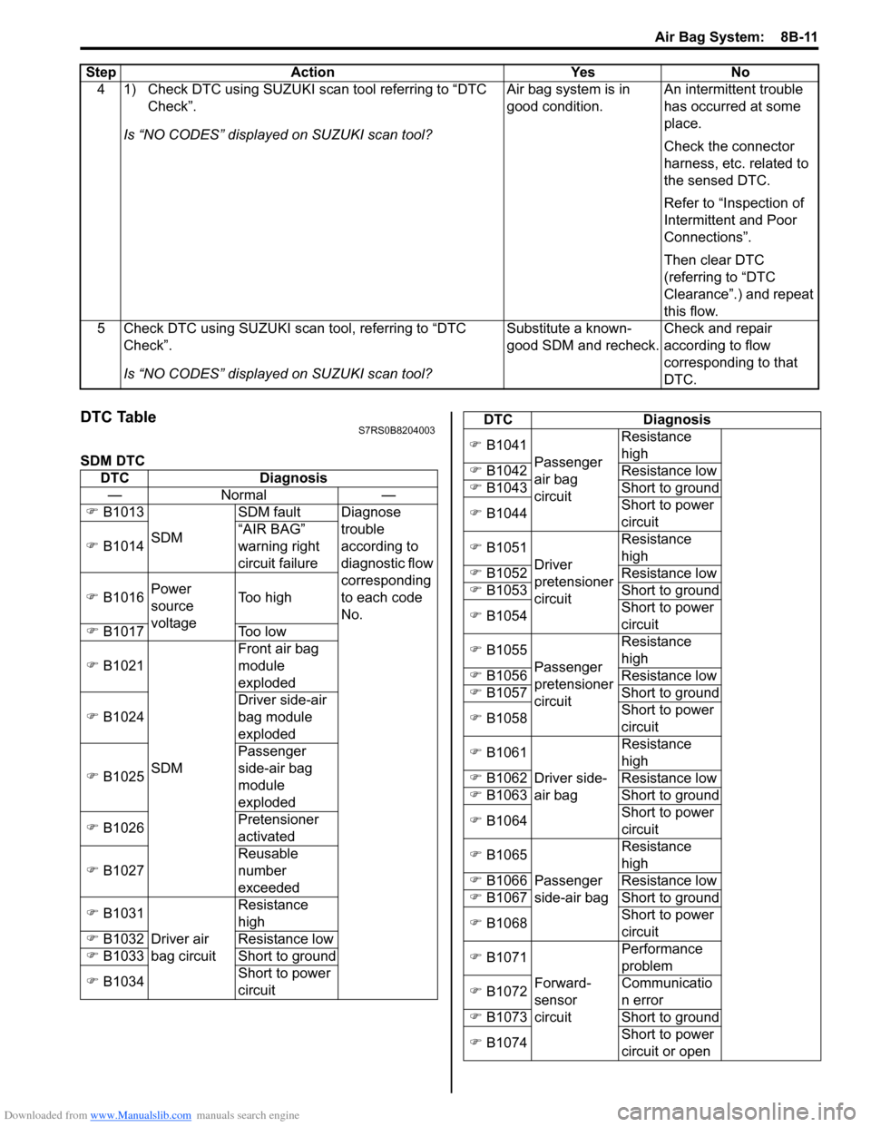
Downloaded from www.Manualslib.com manuals search engine Air Bag System: 8B-11
DTC TableS7RS0B8204003
SDM DTC4 1) Check DTC using SUZUKI scan tool referring to “DTC
Check”.
Is “NO CODES” displayed on SUZUKI scan tool? Air bag system is in
good condition.
An intermittent trouble
has occurred at some
place.
Check the connector
harness, etc. related to
the sensed DTC.
Refer to “Inspection of
Intermittent and Poor
Connections”.
Then clear DTC
(referring to “DTC
Clearance”.) and repeat
this flow.
5 Check DTC using SUZUKI scan tool, referring to “DTC Check”.
Is “NO CODES” displayed on SUZUKI scan tool? Substitute a known-
good SDM and recheck.
Check and repair
according to flow
corresponding to that
DTC.
Step Action Yes No
DTC
Diagnosis
—N orm al —
�) B1013
SDM SDM fault Diagnose
trouble
according to
diagnostic flow
corresponding
to each code
No.
�)
B1014 “AIR BAG”
warning right
circuit failure
�) B1016 Power
source
voltage Too high
�) B1017 Too low
�) B1021
SDM Front air bag
module
exploded
�) B1024 Driver side-air
bag module
exploded
�) B1025 Passenger
side-air bag
module
exploded
�) B1026 Pretensioner
activated
�) B1027 Reusable
number
exceeded
�) B1031
Driver air
bag circuit Resistance
high
�) B1032 Resistance low
�) B1033 Short to ground
�) B1034 Short to power
circuit
�)
B1041
Passenger
air bag
circuit Resistance
high
�) B1042 Resistance low
�) B1043 Short to ground
�) B1044 Short to power
circuit
�) B1051
Driver
pretensioner
circuit Resistance
high
�) B1052 Resistance low
�) B1053 Short to ground
�) B1054 Short to power
circuit
�) B1055
Passenger
pretensioner
circuit Resistance
high
�) B1056 Resistance low
�) B1057 Short to ground
�) B1058 Short to power
circuit
�) B1061
Driver side-
air bag Resistance
high
�) B1062 Resistance low
�) B1063 Short to ground
�) B1064 Short to power
circuit
�) B1065
Passenger
side-air bag Resistance
high
�) B1066 Resistance low
�) B1067 Short to ground
�) B1068 Short to power
circuit
�) B1071
Forward-
sensor
circuit Performance
problem
�) B1072 Communicatio
n error
�) B1073 Short to ground
�) B1074 Short to power
circuit or open
DTC Diagnosis