Defect SUZUKI SWIFT 2007 2.G Service Workshop Manual
[x] Cancel search | Manufacturer: SUZUKI, Model Year: 2007, Model line: SWIFT, Model: SUZUKI SWIFT 2007 2.GPages: 1496, PDF Size: 34.44 MB
Page 33 of 1496
Downloaded from www.Manualslib.com manuals search engine Maintenance and Lubrication: 0B-3
NOTE
тАв тАЬIтАЭ: Inspect and correct or replace if necessary
тАв тАЬRтАЭ: Replace or change
тАв *1: Inspect or replace more frequently if the vehicle is used under dusty conditions.
тАв *2: Clean or replace more frequently if the air from the air conditioning decreases.
Repair Instructions
Accessory Drive Belt InspectionS7RS0B0206001
WARNING!
All inspection and replacement are to be
performed with ENGINE NOT RUNNING.
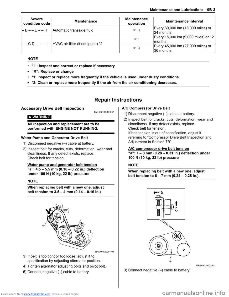
Water Pump and Generator Drive Belt1) Disconnect negative (тАУ) cable at battery.
2) Inspect belt for cracks, cu ts, deformation, wear and
cleanliness. If any defect exists, replace.
Check belt for tension.
Water pump and generator belt tension
тАЬaтАЭ: 4.5 тАУ 5.5 mm (0.18 тАУ 0.22 in.) deflection
under 100 N (10 kg, 22 lb) pressure
NOTE
When replacing belt with a new one, adjust
belt tension to 3.5 тАУ 4 mm (0.14 тАУ 0.16 in.)
3) If belt is too tight or too loose, adjust it to
specification by adjusting alternator position.
4) Tighten alternator adjusting bolts and pivot bolt.
5) Connect negative (тАУ) cable to battery. A/C Compressor Drive Belt
1) Disconnect negative (тАУ) cable at battery.
2) Inspect belt for cracks, cuts, deformation, wear and cleanliness. If any defect exists, replace.
Check belt for tension.
If belt tension is out of specification, adjust it
referring to тАЬCompressor Dr ive Belt Inspection and
Adjustment in Section 7BтАЭ.
A/C compressor drive belt tension
тАЬaтАЭ: 7 тАУ 8 mm (0.28 тАУ 0.31 in.) deflection under
100 N (10 kg, 22 lb) pressure
NOTE
When replacing belt with a new one, adjust
belt tension to 6 тАУ 7 mm (0.24 тАУ 0.28 in.).
3) Connect negative (тАУ) cable to battery.
тАУ B тАУ тАУ E тАУ тАУ H Automatic transaxle fluid
�) R Every 30,000 km (18,000 miles) or
24 months
тАУ тАУ C D тАУ тАУ тАУ тАУ HVAC air filter (if equipped) *2 �)
I Every 15,000 km (9,000 miles) or 12
months
�) R Every 45,000 km (27,000 miles) or
36 months
Severe
condition code MaintenanceMaintenance
operation Maintenance interval
I3RM0A020001-01
I4RS0A020001-01
Page 34 of 1496
Downloaded from www.Manualslib.com manuals search engine 0B-4 Maintenance and Lubrication:
Accessory Drive Belt ReplacementS7RS0B0206002
Water Pump and Generator Drive Belt
Replace belt with new one referring to тАЬWater Pump /
Generator Drive Belt Removal and Installation in Section
1JтАЭ.
A/C Compressor Drive Belt
Replace belt with new one referring to тАЬCompressor
Drive Belt Removal and Inst allation in Section 7BтАЭ.
Valve Lash (Clearance) InspectionS7RS0B0206003
Inspect intake and exhaust valve lash and adjust as
necessary.
Refer to тАЬValve Lash (Clearance) Inspection in Section
1DтАЭ for valve lash inspection and adjustment procedure.
Engine Oil and Filter ChangeS7RS0B0206004
WARNING!
тАв New and used engine oil can be
hazardous.
Be sure to read тАЬWARNINGтАЭ in тАЬGeneral
Precautions in Section 00тАЭ and observe
what is written there.
тАв Step 1) тАУ 7) outlined below must be performed with ENGINE NOT RUNNING.
For Step 8), be sure to have adequate
ventilation while engine is running.
Before draining engine oil, check engine for oil leakage.
If any evidence of leakage is found, make sure to correct
defective part before proceeding to the following work.
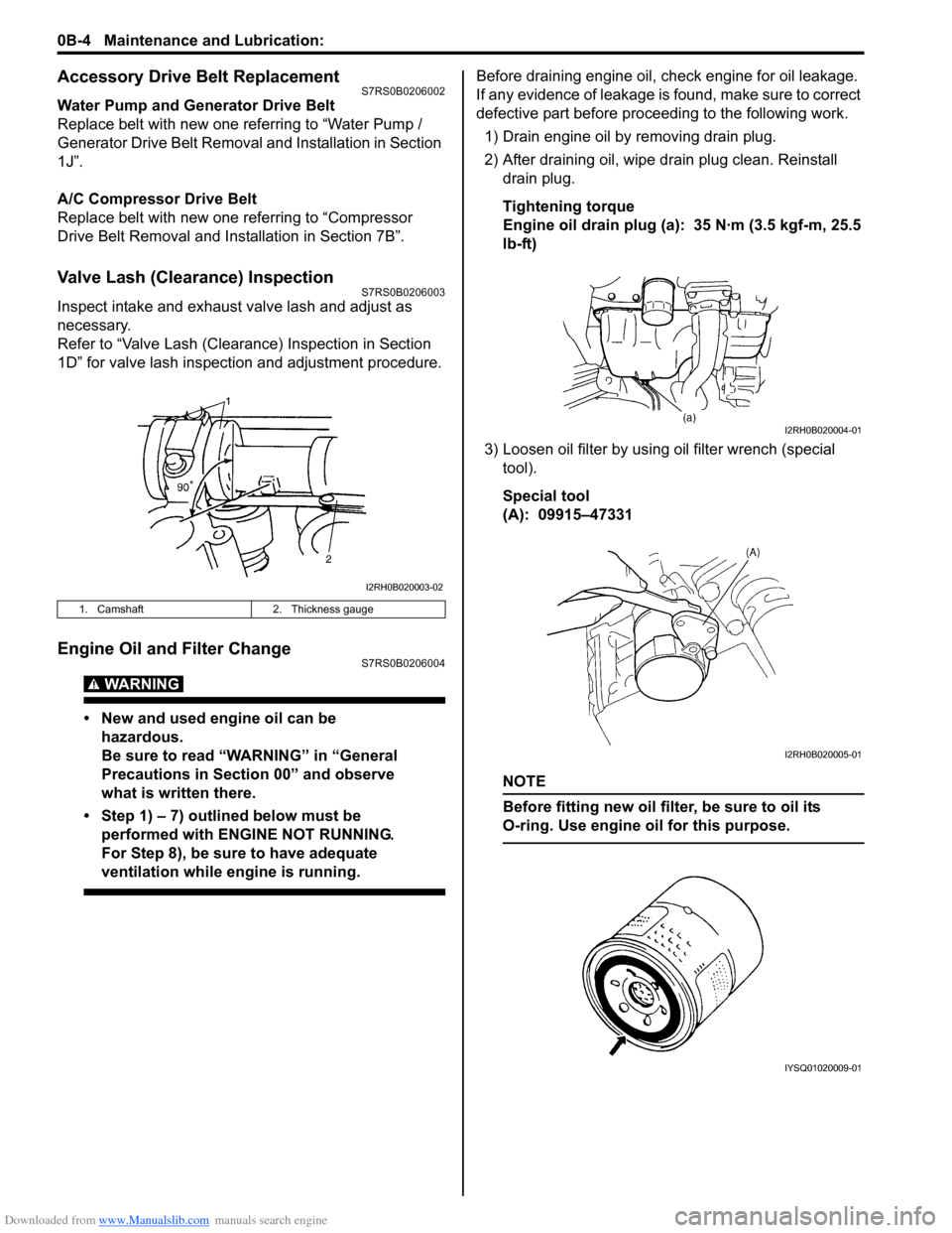
1) Drain engine oil by removing drain plug.
2) After draining oil, wipe drain plug clean. Reinstall drain plug.
Tightening torque
Engine oil drain plug (a): 35 N┬╖m (3.5 kgf-m, 25.5
lb-ft)
3) Loosen oil filter by using oil filter wrench (special
tool).
Special tool
(A): 09915тАУ47331
NOTE
Before fitting new oil filter, be sure to oil its
O-ring. Use engine oil for this purpose.
1. Camshaft 2. Thickness gauge
I2RH0B020003-02
I2RH0B020004-01
I2RH0B020005-01
IYSQ01020009-01
Page 36 of 1496
Downloaded from www.Manualslib.com manuals search engine 0B-6 Maintenance and Lubrication:
Exhaust System InspectionS7RS0B0206006
WARNING!
To avoid danger of being burned, do not
touch exhaust system when it is still hot.
Any service on exhaust system should be
performed when it is cool.
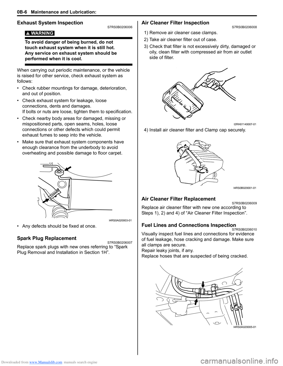
When carrying out periodic maintenance, or the vehicle
is raised for other service, check exhaust system as
follows:
тАв Check rubber mountings for damage, deterioration, and out of position.
тАв Check exhaust system for leakage, loose connections, dents and damages.
If bolts or nuts are loose, tighten them to specification.
тАв Check nearby body areas for damaged, missing or mispositioned parts, ope n seams, holes, loose
connections or other defects which could permit
exhaust fumes to seep into the vehicle.
тАв Make sure that exhaust system components have enough clearance from the underbody to avoid
overheating and possible damage to floor carpet.
тАв Any defects should be fixed at once.
Spark Plug ReplacementS7RS0B0206007
Replace spark plugs with new ones referring to тАЬSpark
Plug Removal and Installation in Section 1HтАЭ.
Air Cleaner Filter InspectionS7RS0B0206008
1) Remove air cleaner case clamps.
2) Take air cleaner filter out of case.
3) Check that filter is not excessively dirty, damaged or oily, clean filter with compressed air from air outlet
side of filter.
4) Install air cleaner filter and Clamp cap securely.
Air Cleaner Filter ReplacementS7RS0B0206009
Replace air cleaner filter with new one according to
Steps 1), 2) and 4) of тАЬAir Cleaner Filter InspectionтАЭ.
Fuel Lines and Connections InspectionS7RS0B0206010
Visually inspect fuel lines and connections for evidence
of fuel leakage, hose cracking and damage. Make sure
all clamps are secure.
Repair leaky joints, if any.
Replace hoses that are suspected of being cracked.
I4RS0A020003-01
I2RH01140007-01
I4RS0B020001-01
I4RS0A020005-01
Page 39 of 1496
Downloaded from www.Manualslib.com manuals search engine Maintenance and Lubrication: 0B-9
Tires InspectionS7RS0B0206020
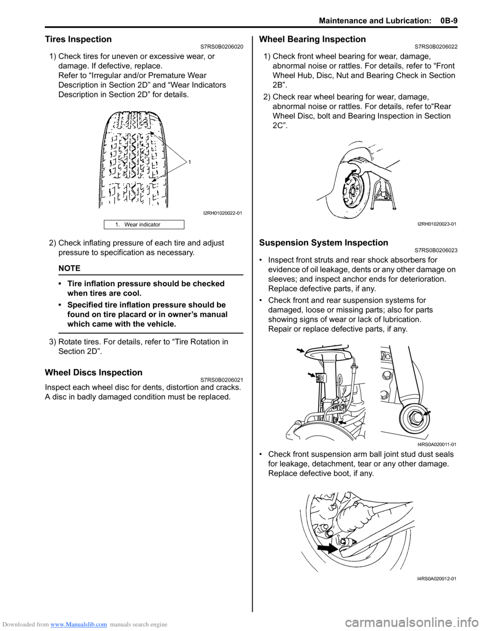
1) Check tires for uneven or excessive wear, or damage. If defective, replace.
Refer to тАЬIrregular and/or Premature Wear
Description in Section 2DтАЭ and тАЬWear Indicators
Description in Section 2DтАЭ for details.
2) Check inflating pressure of each tire and adjust pressure to specification as necessary.
NOTE
тАв Tire inflation pressure should be checked when tires are cool.
тАв Specified tire inflation pressure should be found on tire placard or in ownerтАЩs manual
which came with the vehicle.
3) Rotate tires. For details, refer to тАЬTire Rotation in Section 2DтАЭ.
Wheel Discs InspectionS7RS0B0206021
Inspect each wheel disc for de nts, distortion and cracks.
A disc in badly damaged condition must be replaced.
Wheel Bearing InspectionS7RS0B0206022
1) Check front wheel bearing for wear, damage, abnormal noise or rattles. For details, refer to тАЬFront
Wheel Hub, Disc, Nut and Bearing Check in Section
2BтАЭ.
2) Check rear wheel bearing for wear, damage, abnormal noise or rattles. For details, refer toтАЬRear
Wheel Disc, bolt and Bearing Inspection in Section
2CтАЭ.
Suspension System InspectionS7RS0B0206023
тАв Inspect front struts and rear shock absorbers for evidence of oil leakage, dents or any other damage on
sleeves; and inspect anchor ends for deterioration.
Replace defective parts, if any.
тАв Check front and rear suspension systems for damaged, loose or missing parts; also for parts
showing signs of wear or lack of lubrication.
Repair or replace defective parts, if any.
тАв Check front suspension arm ball joint stud dust seals for leakage, detachment, tear or any other damage.
Replace defective boot, if any.
1. Wear indicator
I2RH01020022-01
I2RH01020023-01
I4RS0A020011-01
I4RS0A020012-01
Page 40 of 1496
Downloaded from www.Manualslib.com manuals search engine 0B-10 Maintenance and Lubrication:
Steering System InspectionS7RS0B0206024
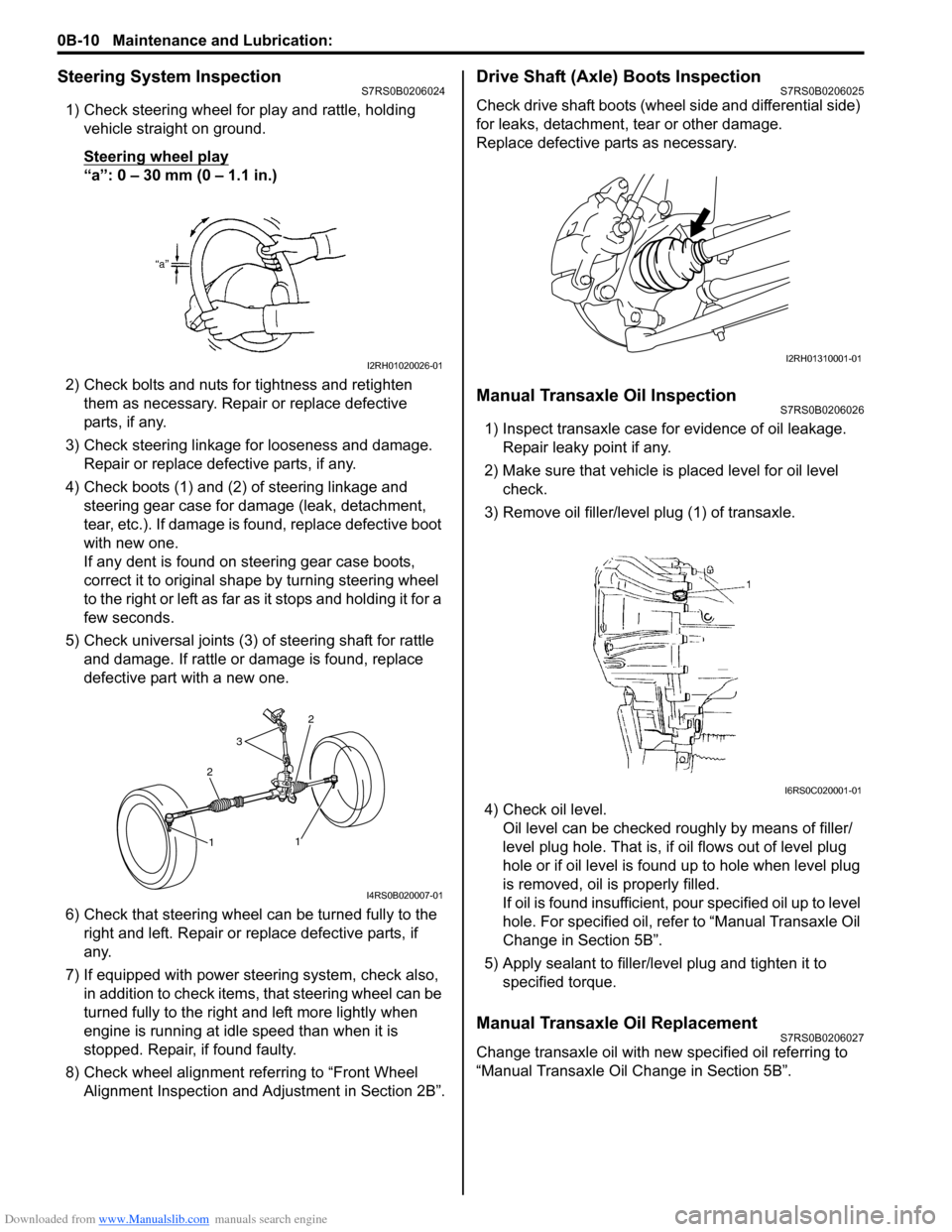
1) Check steering wheel for play and rattle, holding vehicle straight on ground.
Steering wheel play
тАЬaтАЭ: 0 тАУ 30 mm (0 тАУ 1.1 in.)
2) Check bolts and nuts for tightness and retighten them as necessary. Repair or replace defective
parts, if any.
3) Check steering linkage for looseness and damage. Repair or replace defective parts, if any.
4) Check boots (1) and (2) of steering linkage and steering gear case for damage (leak, detachment,
tear, etc.). If damage is fo und, replace defective boot
with new one.
If any dent is found on steering gear case boots,
correct it to original shape by turning steering wheel
to the right or left as far as it stops and holding it for a
few seconds.
5) Check universal joints (3) of steering shaft for rattle and damage. If rattle or damage is found, replace
defective part with a new one.
6) Check that steering wheel can be turned fully to the
right and left. Repair or replace defective parts, if
any.
7) If equipped with power steering system, check also, in addition to check items, that steering wheel can be
turned fully to the right and left more lightly when
engine is running at idle speed than when it is
stopped. Repair, if found faulty.
8) Check wheel alignment referring to тАЬFront Wheel Alignment Inspection and Adjustment in Section 2BтАЭ.
Drive Shaft (Axle) Boots InspectionS7RS0B0206025
Check drive shaft boots (wheel side and differential side)
for leaks, detachment, tear or other damage.
Replace defective parts as necessary.
Manual Transaxle Oil InspectionS7RS0B0206026
1) Inspect transaxle case for evidence of oil leakage. Repair leaky point if any.
2) Make sure that vehicle is placed level for oil level
check.
3) Remove oil filler/leve l plug (1) of transaxle.
4) Check oil level. Oil level can be checked roughly by means of filler/
level plug hole. That is, if oil flows out of level plug
hole or if oil level is found up to hole when level plug
is removed, oil is properly filled.
If oil is found insufficient, po ur specified oil up to level
hole. For specified oil, refe r to тАЬManual Transaxle Oil
Change in Section 5BтАЭ.
5) Apply sealant to filler/leve l plug and tighten it to
specified torque.
Manual Transaxle Oil ReplacementS7RS0B0206027
Change transaxle oil with new specified oil referring to
тАЬManual Transaxle Oil Change in Section 5BтАЭ.
I2RH01020026-01
2
3
2
1
1
I4RS0B020007-01
I2RH01310001-01
I6RS0C020001-01
Page 149 of 1496
Downloaded from www.Manualslib.com manuals search engine Engine General Information and Diagnosis: 1A-99
1) With ignition switch turned OFF, connect scan tool.
2) Turn ON ignition switch and print Freeze Frame Data or write them down using scan tool.
3) Clear DTC using scan tool.
4) Start engine and warm up to normal operating temperature.
5) Operate vehicle with condition as noted freeze frame data for 5 min.
6) Stop vehicle and check DTC and pending DTC.
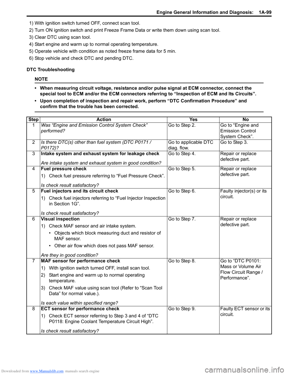
DTC Troubleshooting
NOTE
тАв When measuring circuit voltage, resistance and/ or pulse signal at ECM connector, connect the
special tool to ECM and/or the ECM connectors re ferring to тАЬInspection of ECM and Its CircuitsтАЭ.
тАв Upon completion of inspection and repair work, perform тАЬDTC Confirmation ProcedureтАЭ and confirm that the trouble has been corrected.
Step Action YesNo
1 Was тАЬEngine and Emission Control System CheckтАЭ
performed? Go to Step 2.
Go to тАЬEngine and
Emission Control
System CheckтАЭ.
2 Is there DTC(s) other than fuel system (DTC P0171 /
P0172)? Go to applicable DTC
diag. flow.Go to Step 3.
3 Intake system and exhaust system for leakage check
Are intake system and exhaust system in good condition? Go to Step 4.
Repair or replace
defective part.
4 Fuel pressure check
1) Check fuel pressure referring to тАЬFuel Pressure CheckтАЭ.
Is check result satisfactory? Go to Step 5.
Repair or replace
defective part.
5 Fuel injectors and its circuit check
1) Check fuel injectors referring to тАЬFuel Injector Inspection
in Section 1GтАЭ.
Is check result satisfactory? Go to Step 6.
Faulty injector(s) or its
circuit.
6 Visual inspection
1) Check MAF sensor and air intake system.
тАв Objects which block measur ing duct and resistor of
MAF sensor.
тАв Other air flow which does not pass MAF sensor.
Are they in good condition? Go to Step 7.
Repair or replace
defective part.
7 MAF sensor for performance check
1) With ignition switch turn ed OFF, install scan tool.
2) Start engine and warm up to normal operating temperature.
3) Check MAF value using scan tool (Refer to тАЬScan Tool DataтАЭ for normal value.).
Is each value within specified range? Go to Step 8.
Go to тАЬDTC P0101:
Mass or Volume Air
Flow Circuit Range /
PerformanceтАЭ.
8 ECT sensor for performance check
1) Check ECT sensor referring to Step 3 and 4 of тАЬDTC
P0118: Engine Coolant Temperature Circuit HighтАЭ.
Is check result satisfactory? Go to Step 9.
Faulty ECT sensor or its
circuit.
Page 156 of 1496
Downloaded from www.Manualslib.com manuals search engine 1A-106 Engine General Information and Diagnosis:
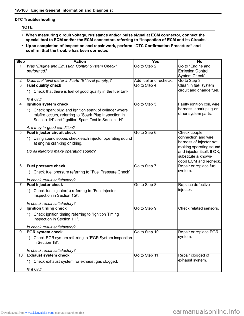
DTC Troubleshooting
NOTE
тАв When measuring circuit voltage, resistance and/or pulse signal at ECM connector, connect the
special tool to ECM and/or the ECM connectors re ferring to тАЬInspection of ECM and Its CircuitsтАЭ.
тАв Upon completion of inspection and repair work, perform тАЬDTC Confirmation ProcedureтАЭ and confirm that the trouble has been corrected.
Step Action YesNo
1 Was тАЬEngine and Emission Control System CheckтАЭ
performed? Go to Step 2.
Go to тАЬEngine and
Emission Control
System CheckтАЭ.
2 Does fuel level meter in dicate тАЬEтАЭ level (empty)? Add fuel and recheck. Go to Step 3.
3 Fuel quality check
1) Check that there is fuel of good quality in the fuel tank.
Is it OK? Go to Step 4.
Clean in fuel system
circuit and change fuel.
4 Ignition system check
1) Check spark plug and ignition spark of cylinder where
misfire occurs, referring to тАЬSpark Plug Inspection in
Section 1HтАЭ and тАЬIgnition Spark Test in Section 1HтАЭ.
Are they in good condition? Go to Step 5.
Faulty ignition coil, wire
harness, spark plug or
other system parts.
5 Fuel injector circuit check
1) Using sound scope, check each injector operating sound
at engine cranking or idling.
Do all injectors ma ke operating sound? Go to Step 6.
Check coupler
connection and wire
harness of injector not
making operating sound
and injector itself. If OK,
substitute a known-
good ECM and recheck.
6 Fuel pressure check
1) Check fuel pressure referring to тАЬFuel Pressure CheckтАЭ.
Is check result satisfactory? Go to Step 7.
Repair or replace fuel
system.
7 Fuel injector check
1) Check fuel injector(s) re ferring to тАЬFuel Injector
Inspection in Section 1GтАЭ.
Is check result satisfactory? Go to Step 8.
Replace defective
injector.
8 Ignition timing check
1) Check ignition timing referring to тАЬIgnition Timing
Inspection in Section 1HтАЭ.
Is check result satisfactory? Go to Step 9.
Check related sensors.
9 EGR system check
1) Check EGR system referring to тАЬEGR System Inspection
in Section 1BтАЭ.
Is check result satisfactory? Go to Step 10. Repair or replace EGR
system.
10 Exhaust system check
1) Check exhaust system for exhaust gas clogged.
Is it OK? Go to Step 11. Repair clogged of
exhaust system.
Page 157 of 1496
Downloaded from www.Manualslib.com manuals search engine Engine General Information and Diagnosis: 1A-107
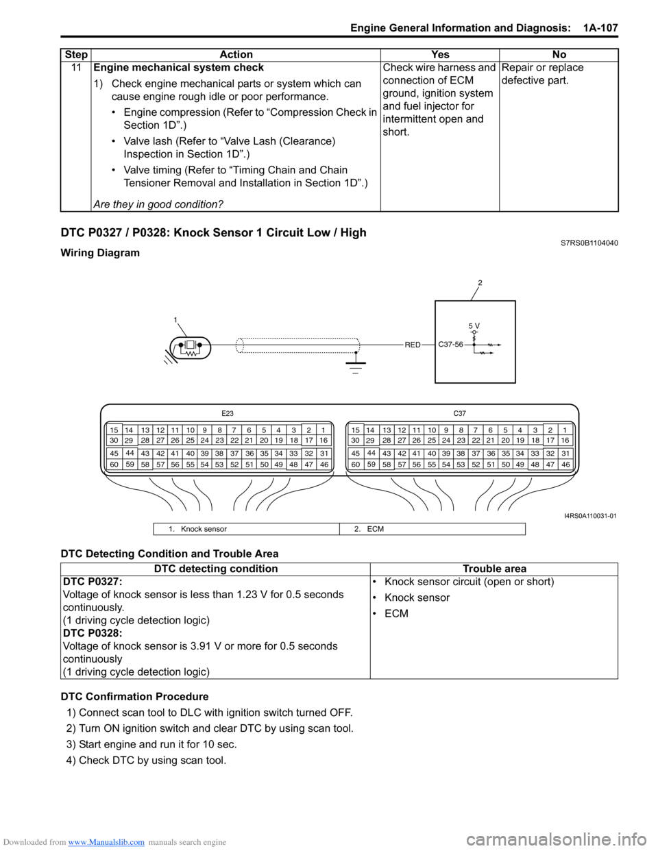
DTC P0327 / P0328: Knock Sensor 1 Circuit Low / HighS7RS0B1104040
Wiring Diagram
DTC Detecting Condition and Trouble Area
DTC Confirmation Procedure1) Connect scan tool to DLC with ignition switch turned OFF.
2) Turn ON ignition switch and clear DTC by using scan tool.
3) Start engine and run it for 10 sec.
4) Check DTC by using scan tool. 11
Engine mechanical system check
1) Check engine mechanical parts or system which can
cause engine rough idle or poor performance.
тАв Engine compression (Refer to тАЬCompression Check in Section 1DтАЭ.)
тАв Valve lash (Refer to тАЬValve Lash (Clearance) Inspection in Section 1DтАЭ.)
тАв Valve timing (Refer to тАЬTiming Chain and Chain Tensioner Removal and Installation in Section 1DтАЭ.)
Are they in good condition? Check wire harness and
connection of ECM
ground, ignition system
and fuel injector for
intermittent open and
short.
Repair or replace
defective part.
Step
Action YesNo
E23 C37
34
1819
567
1011
17
20
47 46
495051
2122
52 16
25 9
24
14
29
55
57 54 53
59
60 58 2
262728
15
30
56 4832 31
34353637
40
42 39 38
44
45 43 41 331
1213
238
34
1819
567
1011
17
20
47 46
495051
2122
52 16
25 9
24
14
29
55
57 54 53
59
60 58 2
262728
15
30
56 4832 31
34353637
40
42 39 38
44
45 43 41 331
1213
238
1 2
REDC37-56
5 V
I4RS0A110031-01
1. Knock sensor
2. ECM
DTC detecting condition Trouble area
DTC P0327:
Voltage of knock sensor is less than 1.23 V for 0.5 seconds
continuously.
(1 driving cycle detection logic)
DTC P0328:
Voltage of knock sensor is 3.91 V or more for 0.5 seconds
continuously
(1 driving cycle detection logic) тАв Knock sensor circuit (open or short)
тАв Knock sensor
тАвECM
Page 165 of 1496
Downloaded from www.Manualslib.com manuals search engine Engine General Information and Diagnosis: 1A-115
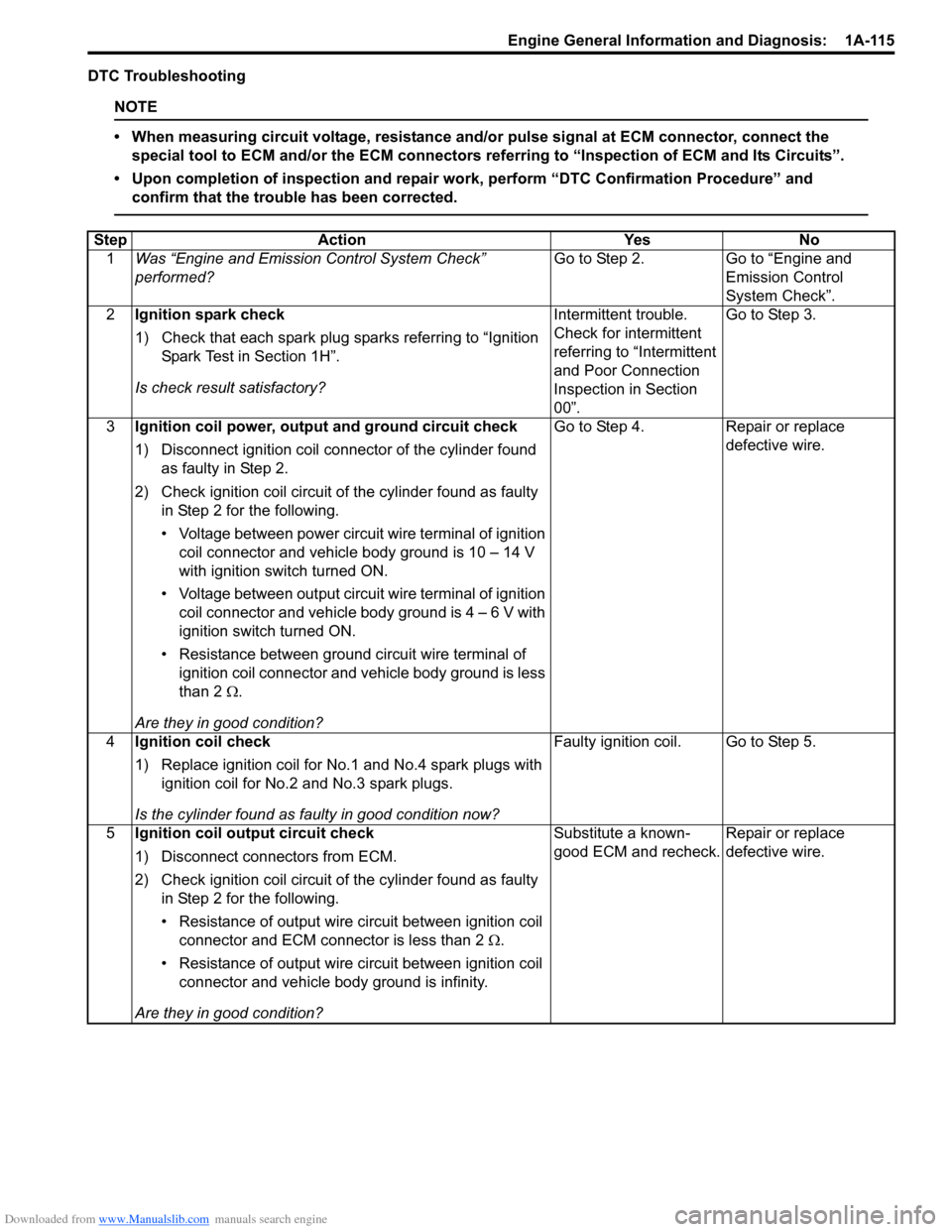
DTC Troubleshooting
NOTE
тАв When measuring circuit voltage, resistance and/or pulse signal at ECM connector, connect the
special tool to ECM and/or the ECM connectors re ferring to тАЬInspection of ECM and Its CircuitsтАЭ.
тАв Upon completion of inspection and repair work, perform тАЬDTC Confirmation ProcedureтАЭ and confirm that the trouble has been corrected.
Step Action YesNo
1 Was тАЬEngine and Emission Control System CheckтАЭ
performed? Go to Step 2.
Go to тАЬEngine and
Emission Control
System CheckтАЭ.
2 Ignition spark check
1) Check that each spark plug sparks referring to тАЬIgnition
Spark Test in Section 1HтАЭ.
Is check result satisfactory? Intermittent trouble.
Check for intermittent
referring to тАЬIntermittent
and Poor Connection
Inspection in Section
00тАЭ.Go to Step 3.
3 Ignition coil power, output and ground circuit check
1) Disconnect ignition coil connector of the cylinder found
as faulty in Step 2.
2) Check ignition coil circuit of the cylinder found as faulty in Step 2 for the following.
тАв Voltage between power circuit wire terminal of ignition coil connector and vehicle body ground is 10 тАУ 14 V
with ignition switch turned ON.
тАв Voltage between output circuit wire terminal of ignition coil connector and vehicle body ground is 4 тАУ 6 V with
ignition switch turned ON.
тАв Resistance between ground circuit wire terminal of ignition coil connector and vehicle body ground is less
than 2 тДж.
Are they in good condition? Go to Step 4.
Repair or replace
defective wire.
4 Ignition coil check
1) Replace ignition coil for No.1 and No.4 spark plugs with
ignition coil for No.2 and No.3 spark plugs.
Is the cylinder found as faulty in good condition now? Faulty ignition coil. Go to Step 5.
5 Ignition coil output circuit check
1) Disconnect connectors from ECM.
2) Check ignition coil circuit of the cylinder found as faulty
in Step 2 for the following.
тАв Resistance of output wire circuit between ignition coil
connector and ECM connector is less than 2 тДж.
тАв Resistance of output wire circuit between ignition coil connector and vehicle b ody ground is infinity.
Are they in good condition? Substitute a known-
good ECM and recheck.
Repair or replace
defective wire.
Page 171 of 1496
Downloaded from www.Manualslib.com manuals search engine Engine General Information and Diagnosis: 1A-121
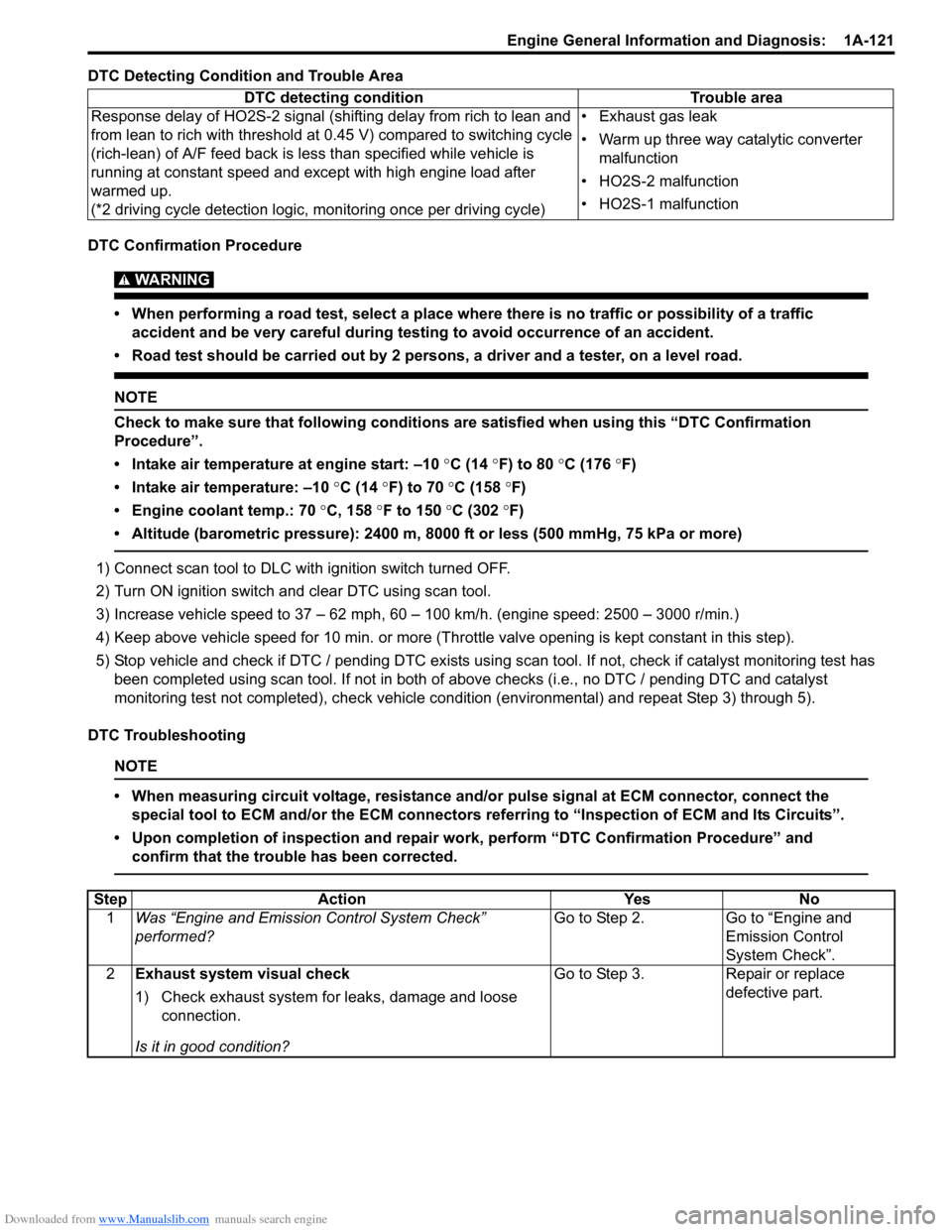
DTC Detecting Condition and Trouble Area
DTC Confirmation Procedure
WARNING!
тАв When performing a road test, select a place where there is no traffic or possibility of a traffic accident and be very careful during testing to avoid occurrence of an accident.
тАв Road test should be carried out by 2 persons, a driver and a tester, on a level road.
NOTE
Check to make sure that following conditions ar e satisfied when using this тАЬDTC Confirmation
ProcedureтАЭ.
тАв Intake air temperature at engine start: тАУ10 ┬░C (14 ┬░ F) to 80 ┬░C (176 ┬░F)
тАв Intake air temperature: тАУ10 ┬░C (14 ┬░F) to 70 ┬░C (158 ┬░F)
тАв Engine coolant temp.: 70 ┬░C, 158 ┬░F to 150 ┬░C (302 ┬░F)
тАв Altitude (barometric pressure): 2400 m, 8000 ft or less (500 mmHg, 75 kPa or more)
1) Connect scan tool to DLC with ignition switch turned OFF.
2) Turn ON ignition switch and clear DTC using scan tool.
3) Increase vehicle speed to 37 тАУ 62 mph, 60 тАУ 100 km/h. (engine speed: 2500 тАУ 3000 r/min.)
4) Keep above vehicle speed for 10 min. or more (Thr ottle valve opening is kept constant in this step).
5) Stop vehicle and check if DTC / pending DTC exists using sc an tool. If not, check if catalyst monitoring test has
been completed using scan tool. If not in both of above checks (i.e., no DTC / pending DTC and catalyst
monitoring test not completed), check vehicle cond ition (environmental) and repeat Step 3) through 5).
DTC Troubleshooting
NOTE
тАв When measuring circuit voltage, resistance and/ or pulse signal at ECM connector, connect the
special tool to ECM and/or the ECM connectors re ferring to тАЬInspection of ECM and Its CircuitsтАЭ.
тАв Upon completion of inspection and repair work, perform тАЬDTC Confirmation ProcedureтАЭ and confirm that the trouble has been corrected.
DTC detecting condition Trouble area
Response delay of HO2S-2 signal (shifting delay from rich to lean and
from lean to rich with threshold at 0.45 V) compared to switching cycle
(rich-lean) of A/F feed back is less than specified while vehicle is
running at constant speed and except with high engine load after
warmed up.
(*2 driving cycle detection logic, monitoring once per driving cycle) тАв Exhaust gas leak
тАв Warm up three way catalytic converter
malfunction
тАв HO2S-2 malfunction
тАв HO2S-1 malfunction
Step Action YesNo
1 Was тАЬEngine and Emission Control System CheckтАЭ
performed? Go to Step 2.
Go to тАЬEngine and
Emission Control
System CheckтАЭ.
2 Exhaust system visual check
1) Check exhaust system for leaks, damage and loose
connection.
Is it in good condition? Go to Step 3.
Repair or replace
defective part.