Defect SUZUKI SWIFT 2007 2.G Service Manual PDF
[x] Cancel search | Manufacturer: SUZUKI, Model Year: 2007, Model line: SWIFT, Model: SUZUKI SWIFT 2007 2.GPages: 1496, PDF Size: 34.44 MB
Page 975 of 1496
Downloaded from www.Manualslib.com manuals search engine Air Conditioning System: Manual Type 7B-27
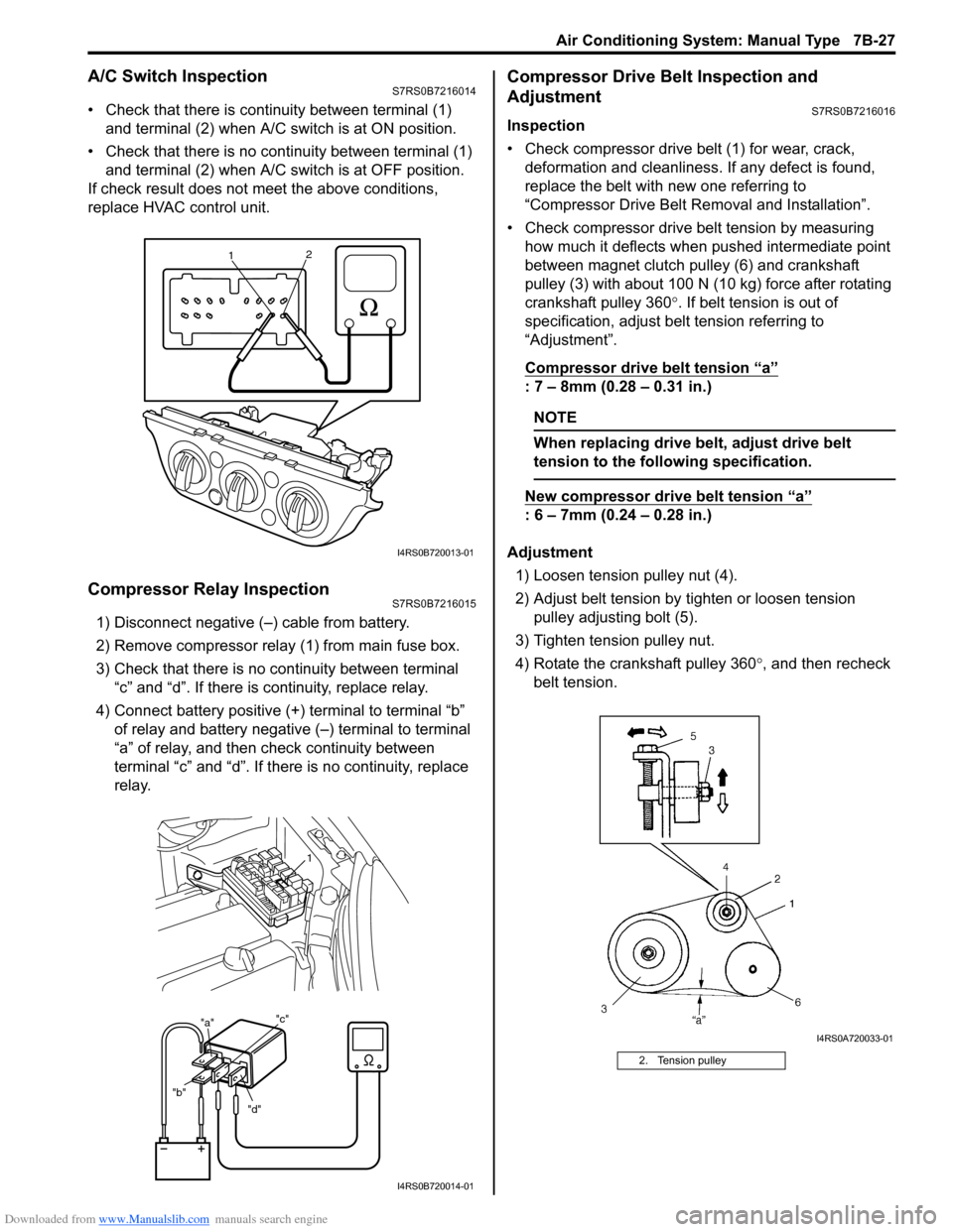
A/C Switch InspectionS7RS0B7216014
тАв Check that there is continuity between terminal (1) and terminal (2) when A/C s witch is at ON position.
тАв Check that there is no continuity between terminal (1) and terminal (2) when A/C s witch is at OFF position.
If check result does not meet the above conditions,
replace HVAC control unit.
Compressor Relay InspectionS7RS0B7216015
1) Disconnect negative (тАУ) cable from battery.
2) Remove compressor relay (1) from main fuse box.
3) Check that there is no continuity between terminal тАЬcтАЭ and тАЬdтАЭ. If there is continuity, replace relay.
4) Connect battery positive (+ ) terminal to terminal тАЬbтАЭ
of relay and battery negative (тАУ) terminal to terminal
тАЬaтАЭ of relay, and then check continuity between
terminal тАЬcтАЭ and тАЬdтАЭ. If there is no continuity, replace
relay.
Compressor Drive Belt Inspection and
Adjustment
S7RS0B7216016
Inspection
тАв Check compressor drive belt (1) for wear, crack, deformation and cleanliness. If any defect is found,
replace the belt with new one referring to
тАЬCompressor Drive Belt Re moval and InstallationтАЭ.
тАв Check compressor drive belt tension by measuring how much it deflects when pushed intermediate point
between magnet clutch pulley (6) and crankshaft
pulley (3) with about 100 N (10 kg) force after rotating
crankshaft pulley 360 ┬░. If belt tension is out of
specification, adjust belt tension referring to
тАЬAdjustmentтАЭ.
Compressor drive belt tension
тАЬaтАЭ
: 7 тАУ 8mm (0.28 тАУ 0.31 in.)
NOTE
When replacing drive belt, adjust drive belt
tension to the following specification.
New compressor dr ive belt tension тАЬaтАЭ
: 6 тАУ 7mm (0.24 тАУ 0.28 in.)
Adjustment 1) Loosen tension pulley nut (4).
2) Adjust belt tension by ti ghten or loosen tension
pulley adjusting bolt (5).
3) Tighten tension pulley nut.
4) Rotate the crankshaft pulley 360 ┬░, and then recheck
belt tension.
1 2
I4RS0B720013-01
"d"
"b" "a"
"c"
1
I4RS0B720014-01
2. Tension pulley
I4RS0A720033-01
Page 1011 of 1496
Downloaded from www.Manualslib.com manuals search engine Air Conditioning System: Automatic Type 7B-63
DTC B1546: A/C Refrigerant Pressure MalfunctionS7RS0B7224018
DTC Detecting Condition and Trouble Area
DTC Troubleshooting
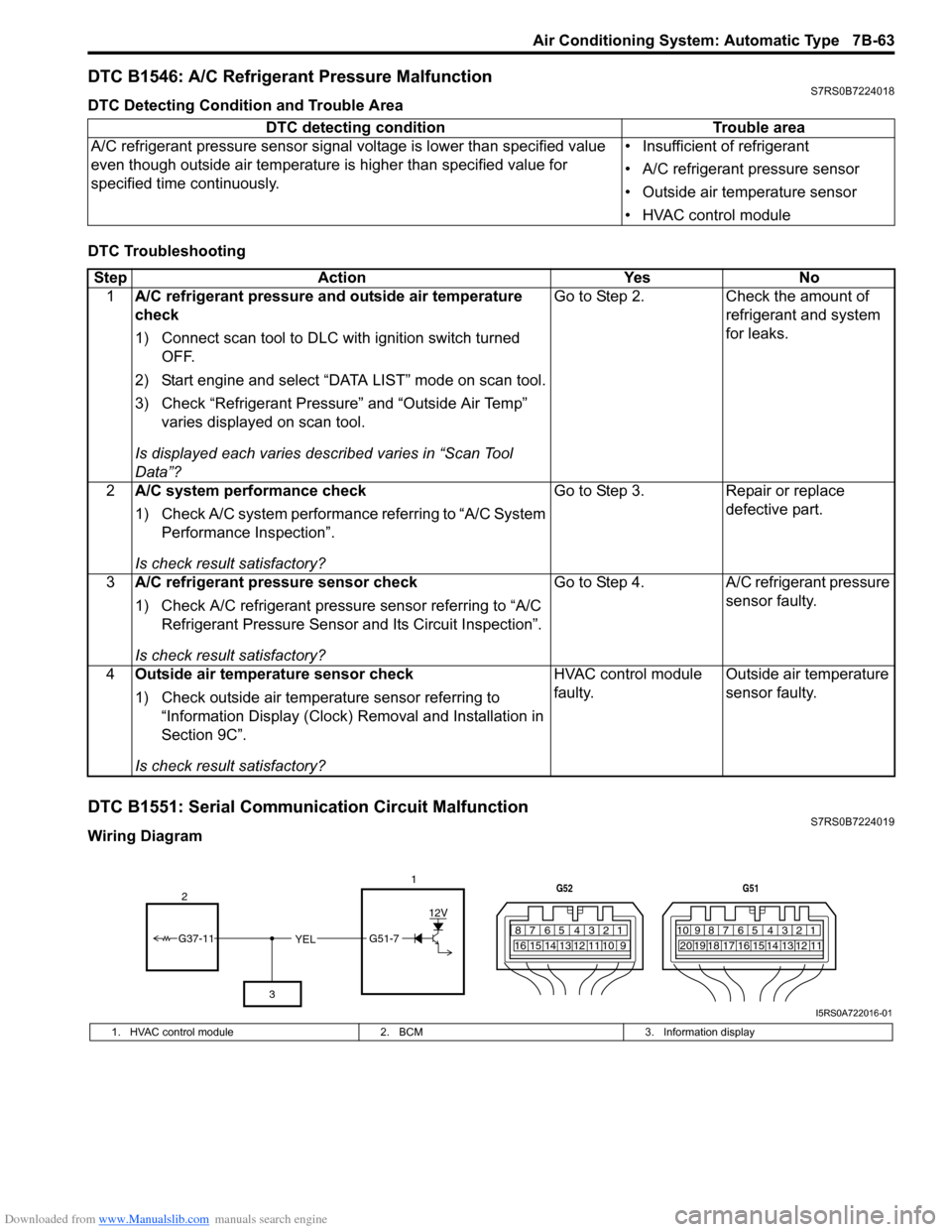
DTC B1551: Serial Communication Circuit MalfunctionS7RS0B7224019
Wiring DiagramDTC detecting condition Trouble area
A/C refrigerant pressure sensor signal voltage is lower t han specified value
even though outside air temperature is higher than specified value for
specified time continuously. тАв Insufficient of refrigerant
тАв A/C refrigerant pressure sensor
тАв Outside air temperature sensor
тАв HVAC control module
Step
Action YesNo
1 A/C refrigerant pressure and outside air temperature
check
1) Connect scan tool to DLC with ignition switch turned
OFF.
2) Start engine and select тАЬDATA LISTтАЭ mode on scan tool.
3) Check тАЬRefrigerant PressureтАЭ and тАЬOutside Air TempтАЭ varies displayed on scan tool.
Is displayed each va ries described varies in тАЬScan Tool
DataтАЭ? Go to Step 2.
Check the amount of
refrigerant and system
for leaks.
2 A/C system performance check
1) Check A/C system performance referring to тАЬA/C System
Performance InspectionтАЭ.
Is check result satisfactory? Go to Step 3.
Repair or replace
defective part.
3 A/C refrigerant pressure sensor check
1) Check A/C refrigerant pressure sensor referring to тАЬA/C
Refrigerant Pressure Sensor and Its Circuit InspectionтАЭ.
Is check result satisfactory? Go to Step 4.
A/C refrigerant pressure
sensor faulty.
4 Outside air temperature sensor check
1) Check outside air temperature sensor referring to
тАЬInformation Display (Clock) Removal and Installation in
Section 9CтАЭ.
Is check result satisfactory? HVAC control module
faulty.
Outside air temperature
sensor faulty.
YEL17812910
65 431516 14 13 12 11
G52
789101920121112
65 431718 16 15 14 13
G51
G51-7
12V
2
3
G37-11
I5RS0A722016-01
1. HVAC control module 2. BCM3. Information display
Page 1032 of 1496
Downloaded from www.Manualslib.com manuals search engine 8A-1 Seat Belts:
Restraint
Seat Belts
Precautions
Precautions on Service and Diagnosis of Seat
Belt
S7RS0B8100001
WARNING!
If replacing seat belt is necessary, replace
buckle and seat belt assembly together as a
set. This is for the reason of ensuring locking
of tongue plate with buckle. If these parts are
replaced individually, such a locking
condition may become unreliable. For this
reason, SUZUKI will supply only the spare
buckle and seat belt assembly in a set part.
Before servicing or replacing seat belts, refer to the
following precautionary items.
тАв Seat belts should be normal relative to strap retractor and buckle portions. тАв Keep sharp edges and damaging objects away from
belts.
тАв Avoid bending or damaging any portion of belt buckle or latch plate.
тАв Do not bleach or dye belt webbing. (Use only mild soap and lukewarm water to clean it.)
тАв When installing a seat belt anchor bolt, it should be tightened by hand at first to prevent cross-threading
and then to specified torque.
тАв Do not attempt any repair s on retractor mechanisms
or retractor covers. Replace defective assemblies with
new replacement parts.
тАв Keep belts dry and clean at all times.
тАв If there exist any parts in question, replace such parts.
тАв Replace belts whose webbing is cut or otherwise damaged.
тАв Do not put anything into trim panel opening which seat belt webbing passes through.
General Description
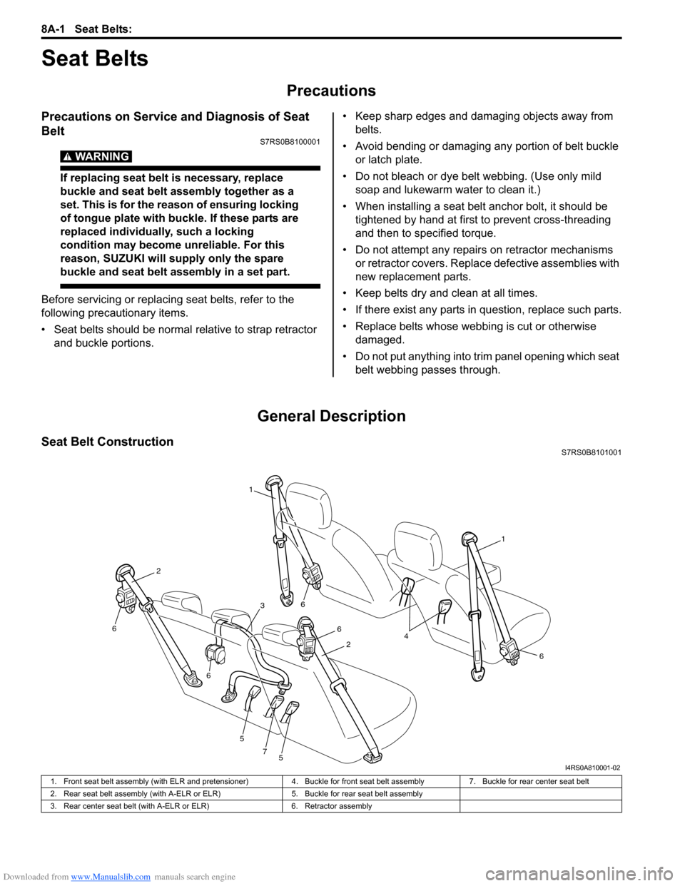
Seat Belt ConstructionS7RS0B8101001
1
1
6
6
6
5
5
7
6
6
2
2
3
4
I4RS0A810001-02
1. Front seat belt assembly (with ELR and pretensioner) 4. Buckle for front seat belt assembly7. Buckle for rear center seat belt
2. Rear seat belt assembly (with A-ELR or ELR) 5. Buckle for rear seat belt assembly
3. Rear center seat belt (with A-ELR or ELR) 6. Retractor assembly
Page 1131 of 1496
Downloaded from www.Manualslib.com manuals search engine Air Bag System: 8B-93
Contact Coil Cable and Its Circuit CheckS7RS0B8204047
TroubleshootingStep Action Yes No 1 Driver air bag circuit check
1) Remove driver air bag (inflator) module referring to
тАЬDriver Air Bag (Inflator) Module Removal and
InstallationтАЭ.
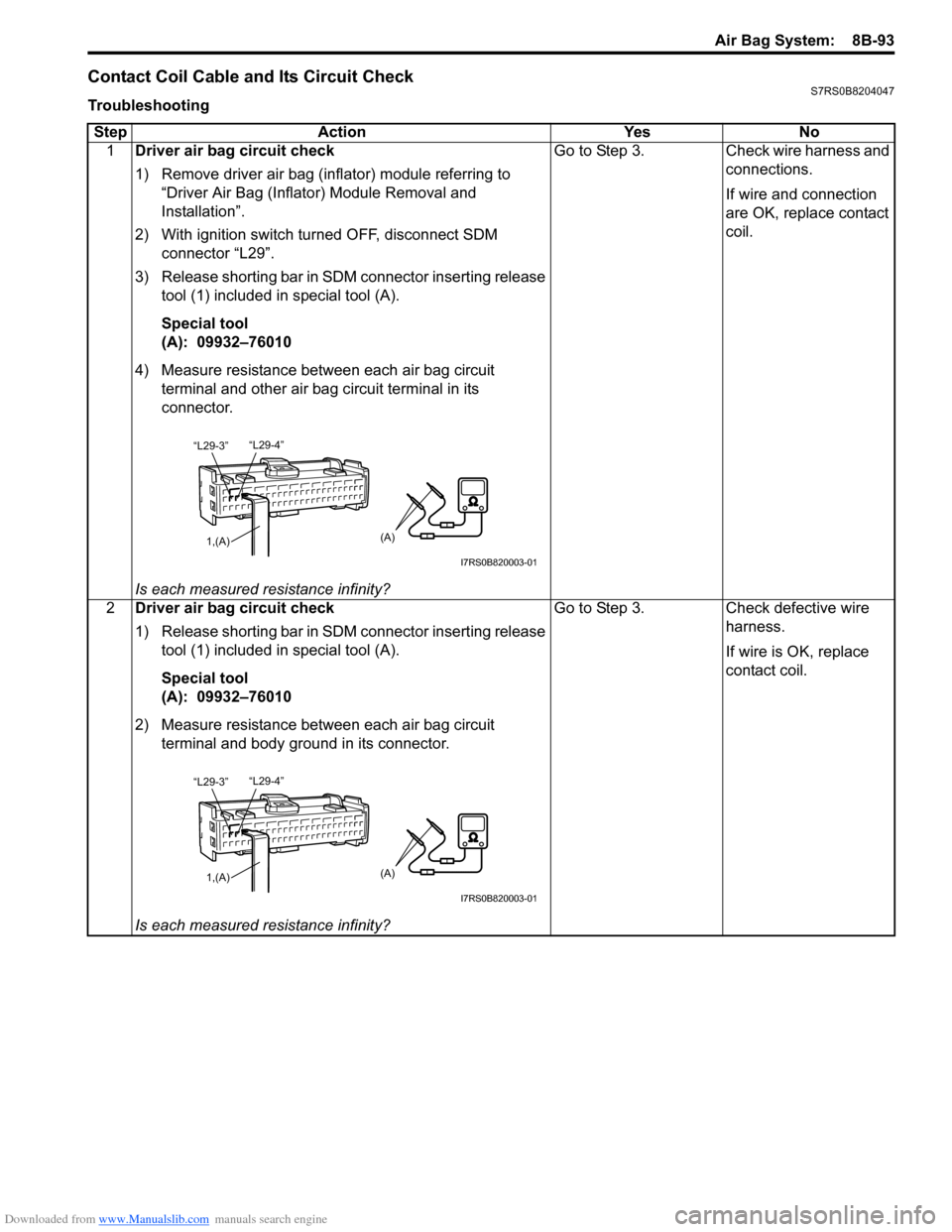
2) With ignition switch turned OFF, disconnect SDM connector тАЬL29тАЭ.
3) Release shorting bar in SDM connector inserting release tool (1) included in special tool (A).
Special tool
(A): 09932тАУ76010
4) Measure resistance between each air bag circuit terminal and other air bag circuit terminal in its
connector.
Is each measured resistance infinity? Go to Step 3. Check wire harness and
connections.
If wire and connection
are OK, replace contact
coil.
2 Driver air bag circuit check
1) Release shorting bar in SDM connector inserting release
tool (1) included in special tool (A).
Special tool
(A): 09932тАУ76010
2) Measure resistance between each air bag circuit terminal and body ground in its connector.
Is each measured resistance infinity? Go to Step 3. Check defective wire
harness.
If wire is OK, replace
contact coil.
тАЬL29-4тАЭ
тАЬL29-3тАЭ
1,(A)(A)
I7RS0B820003-01
тАЬL29-4тАЭ
тАЬL29-3тАЭ
1,(A)(A)
I7RS0B820003-01
Page 1311 of 1496
Downloaded from www.Manualslib.com manuals search engine Instrumentation / Driver Info. / Horn: 9C-16
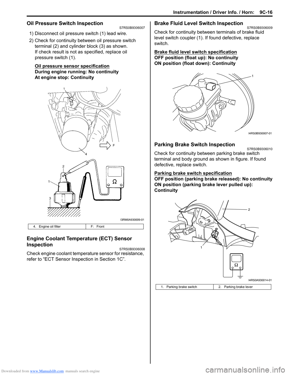
Oil Pressure Switch InspectionS7RS0B9306007
1) Disconnect oil pressure switch (1) lead wire.
2) Check for continuity between oil pressure switch terminal (2) and cylinder block (3) as shown.
If check result is not as specified, replace oil
pressure switch (1).
Oil pressure sensor specification
During engine running: No continuity
At engine stop: Continuity
Engine Coolant Temperature (ECT) Sensor
Inspection
S7RS0B9306008
Check engine coolant temperat ure sensor for resistance,
refer to тАЬECT Sensor Inspection in Section 1CтАЭ.
Brake Fluid Level Switch InspectionS7RS0B9306009
Check for continuity between terminals of brake fluid
level switch coupler (1). If found defective, replace
switch.
Brake fluid level switch specification
OFF position (float up): No continuity
ON position (float down): Continuity
Parking Brake Switch InspectionS7RS0B9306010
Check for continuity between parking brake switch
terminal and body ground as shown in figure. If found
defective, replace switch.
Parking brake switch specification
OFF position (parking brake released): No continuity
ON position (parking brake lever pulled up):
Continuity
4. Engine oil filter F: Front
I3RM0A930009-01
1. Parking brake switch 2. Parking brake lever
1
I4RS0B930007-01
12
I4RS0A930014-01
Page 1312 of 1496
Downloaded from www.Manualslib.com manuals search engine 9C-17 Instrumentation / Driver Info. / Horn:
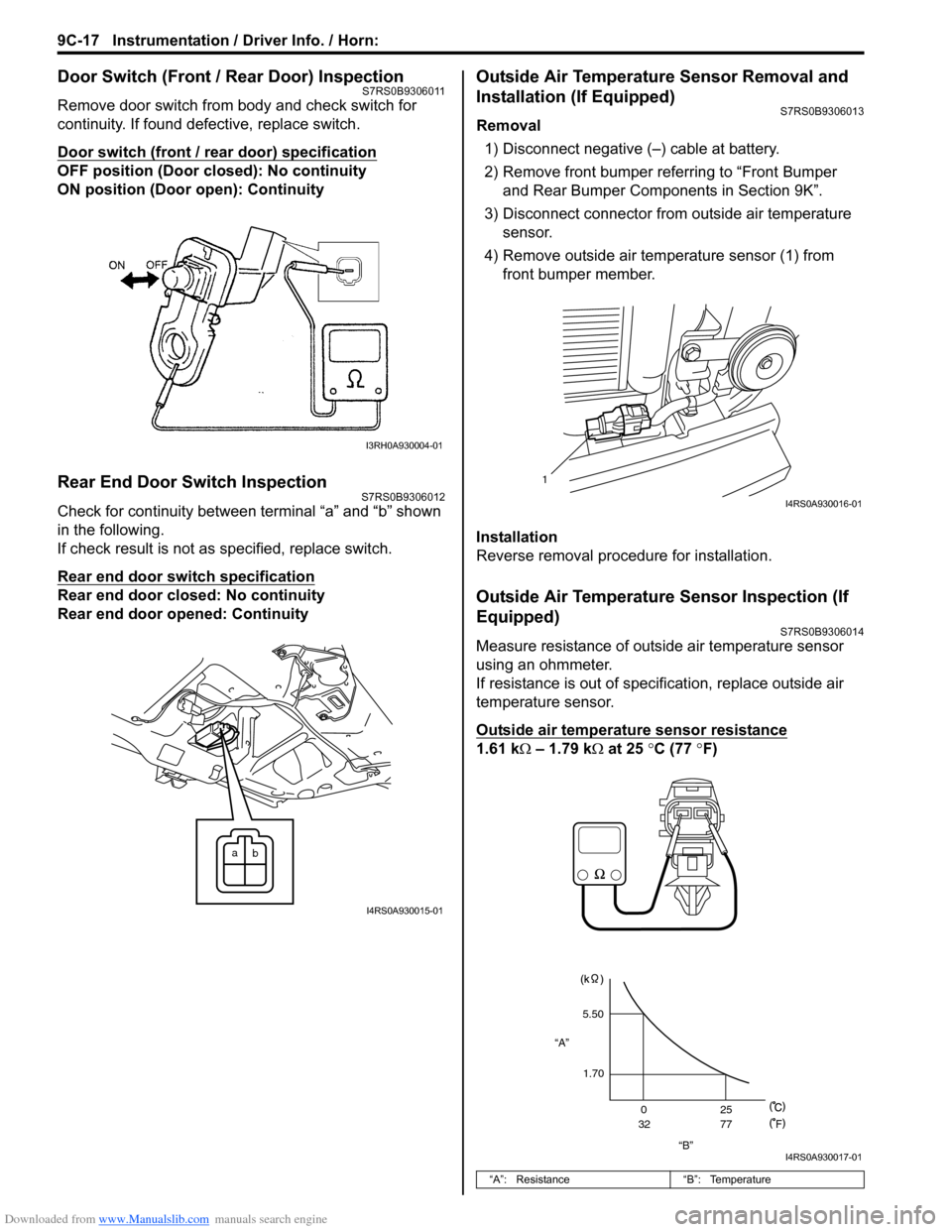
Door Switch (Front / Rear Door) InspectionS7RS0B9306011
Remove door switch from body and check switch for
continuity. If found defective, replace switch.
Door switch (front / rear door) specification
OFF position (Door closed): No continuity
ON position (Door open): Continuity
Rear End Door Switch InspectionS7RS0B9306012
Check for continuity between terminal тАЬaтАЭ and тАЬbтАЭ shown
in the following.
If check result is not as specified, replace switch.
Rear end door switch specification
Rear end door closed: No continuity
Rear end door opened: Continuity
Outside Air Temperature Sensor Removal and
Installation (If Equipped)
S7RS0B9306013
Removal
1) Disconnect negative (тАУ) cable at battery.
2) Remove front bumper referring to тАЬFront Bumper and Rear Bumper Components in Section 9KтАЭ.
3) Disconnect connector from outside air temperature sensor.
4) Remove outside air temperature sensor (1) from front bumper member.
Installation
Reverse removal procedure for installation.
Outside Air Temperature Sensor Inspection (If
Equipped)
S7RS0B9306014
Measure resistance of outside air temperature sensor
using an ohmmeter.
If resistance is out of specif ication, replace outside air
temperature sensor.
Outside air temperature sensor resistance
1.61 kтДж тАУ 1.79 k тДж at 25 ┬░C (77 ┬░F)
I3RH0A930004-01
a
b
I4RS0A930015-01
тАЬAтАЭ: Resistance тАЬBтАЭ: Temperature
1
I4RS0A930016-01
тАЬBтАЭ
тАЬAтАЭ
5.50
1.70 0
32 25
77
F
I4RS0A930017-01
Page 1342 of 1496
Downloaded from www.Manualslib.com manuals search engine 9E-15 Glass / Windows / Mirrors:
Rear End Door Window Defogger Wire
Inspection
S7RS0B9506014
NOTE
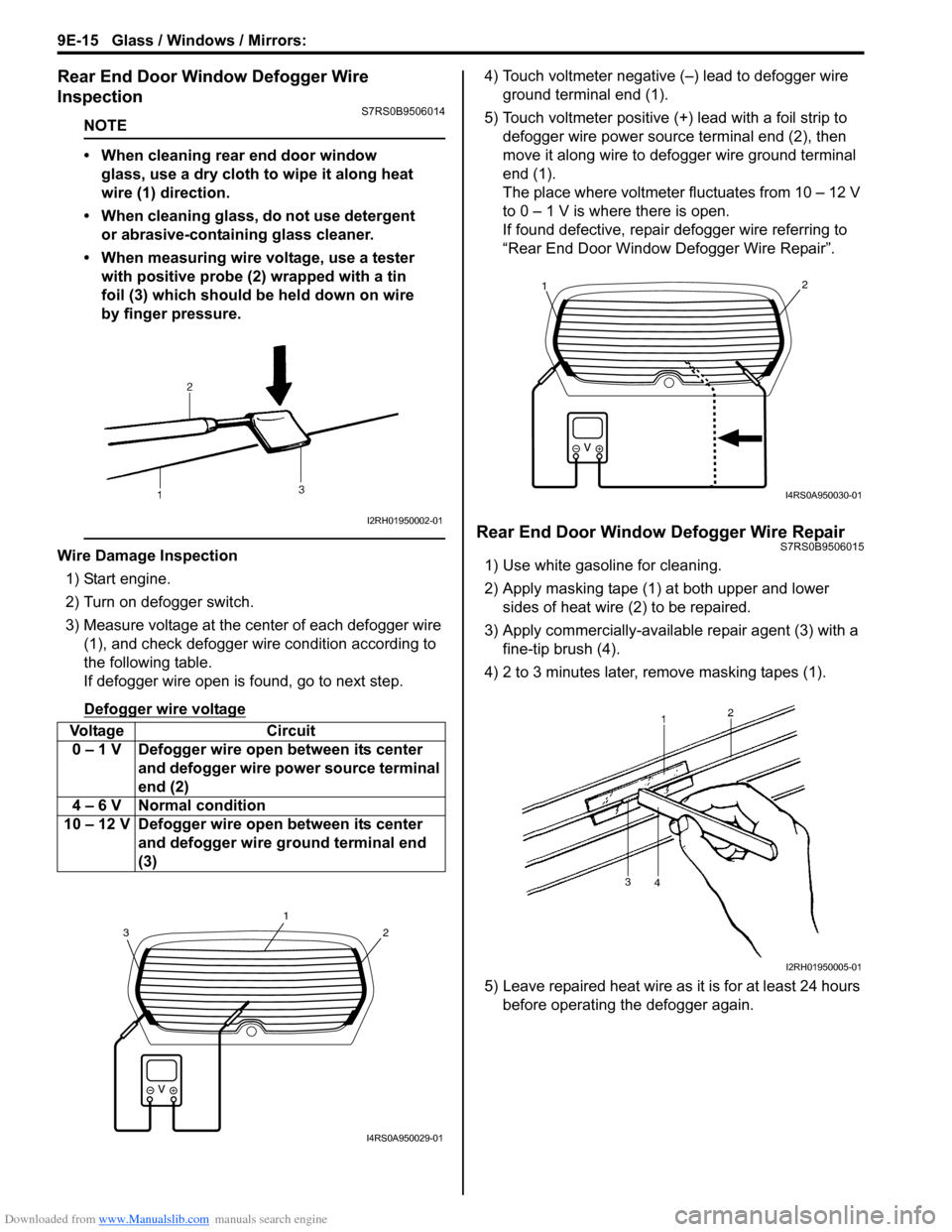
тАв When cleaning rear end door window glass, use a dry cloth to wipe it along heat
wire (1) direction.
тАв When cleaning glass, do not use detergent or abrasive-containing glass cleaner.
тАв When measuring wire voltage, use a tester with positive probe (2) wrapped with a tin
foil (3) which should be held down on wire
by finger pressure.
Wire Damage Inspection
1) Start engine.
2) Turn on defogger switch.
3) Measure voltage at the center of each defogger wire (1), and check defogger wire condition according to
the following table.
If defogger wire open is found, go to next step.
Defogger wire voltage
4) Touch voltmeter negative (тАУ) lead to defogger wire ground terminal end (1).
5) Touch voltmeter positive (+) lead with a foil strip to defogger wire power source terminal end (2), then
move it along wire to defogger wire ground terminal
end (1).
The place where voltmeter fluctuates from 10 тАУ 12 V
to 0 тАУ 1 V is where there is open.
If found defective, repair defogger wire referring to
тАЬRear End Door Window Defogger Wire RepairтАЭ.
Rear End Door Window Defogger Wire RepairS7RS0B9506015
1) Use white gasoline for cleaning.
2) Apply masking tape (1) at both upper and lower sides of heat wire (2) to be repaired.
3) Apply commercially-available repair agent (3) with a fine-tip brush (4).
4) 2 to 3 minutes later, remove masking tapes (1).
5) Leave repaired heat wire as it is for at least 24 hours before operating the defogger again.
Voltage Circuit
0 тАУ 1 V Defogger wire open between its center and defogger wire power source terminal
end (2)
4 тАУ 6 V Normal condition
10 тАУ 12 V Defogger wire open between its center and defogger wire ground terminal end
(3)
I2RH01950002-01
2
1
3
I4RS0A950029-01
21
I4RS0A950030-01
I2RH01950005-01