Defect SUZUKI SWIFT 2007 2.G Service Owner's Guide
[x] Cancel search | Manufacturer: SUZUKI, Model Year: 2007, Model line: SWIFT, Model: SUZUKI SWIFT 2007 2.GPages: 1496, PDF Size: 34.44 MB
Page 465 of 1496
Downloaded from www.Manualslib.com manuals search engine Rear Suspension: 2C-11
Installation
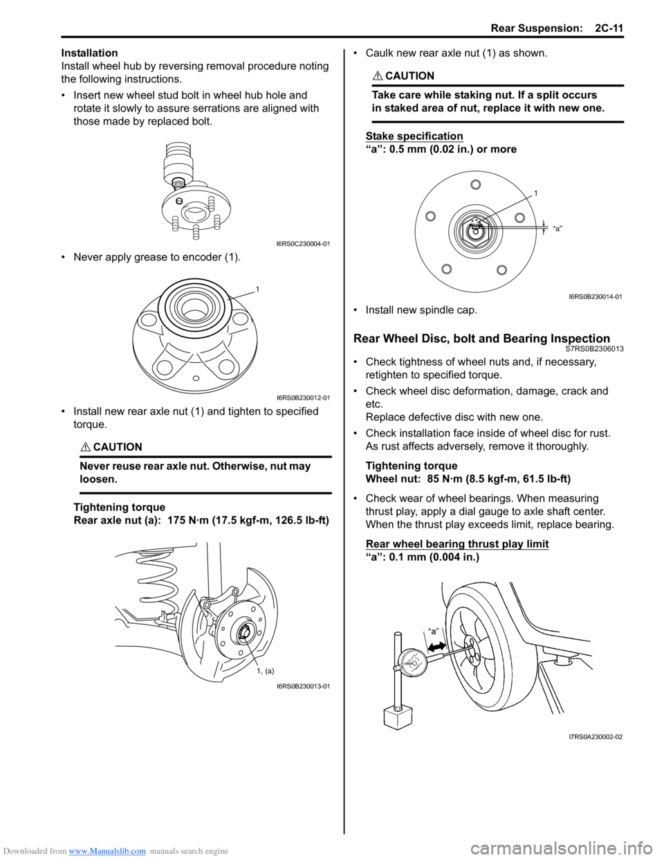
Install wheel hub by reversing removal procedure noting
the following instructions.
тАв Insert new wheel stud bolt in wheel hub hole and rotate it slowly to assure serrations are aligned with
those made by replaced bolt.
тАв Never apply grease to encoder (1).
тАв Install new rear axle nut (1) and tighten to specified torque.
CAUTION!
Never reuse rear axle nut. Otherwise, nut may
loosen.
Tightening torque
Rear axle nut (a): 175 N┬╖m (17.5 kgf-m, 126.5 lb-ft) тАв Caulk new rear axle nut (1) as shown.
CAUTION!
Take care while staking nut. If a split occurs
in staked area of nut,
replace it with new one.
Stake specification
тАЬaтАЭ: 0.5 mm (0.02 in.) or more
тАв Install new spindle cap.
Rear Wheel Disc, bolt and Bearing InspectionS7RS0B2306013
тАв Check tightness of wheel nuts and, if necessary, retighten to specified torque.
тАв Check wheel disc deformation, damage, crack and etc.
Replace defective disc with new one.
тАв Check installation face insi de of wheel disc for rust.
As rust affects adversely, remove it thoroughly.
Tightening torque
Wheel nut: 85 N┬╖m (8.5 kgf-m, 61.5 lb-ft)
тАв Check wear of wheel bearings. When measuring thrust play, apply a dial gauge to axle shaft center.
When the thrust play exce eds limit, replace bearing.
Rear wheel bearing thrust play
limit
тАЬaтАЭ: 0.1 mm (0.004 in.)
I6RS0C230004-01
1
I6RS0B230012-01
1, (a)
I6RS0B230013-01
1
тАЬaтАЭ
I6RS0B230014-01
I7RS0A230002-02
Page 466 of 1496
Downloaded from www.Manualslib.com manuals search engine 2C-12 Rear Suspension:
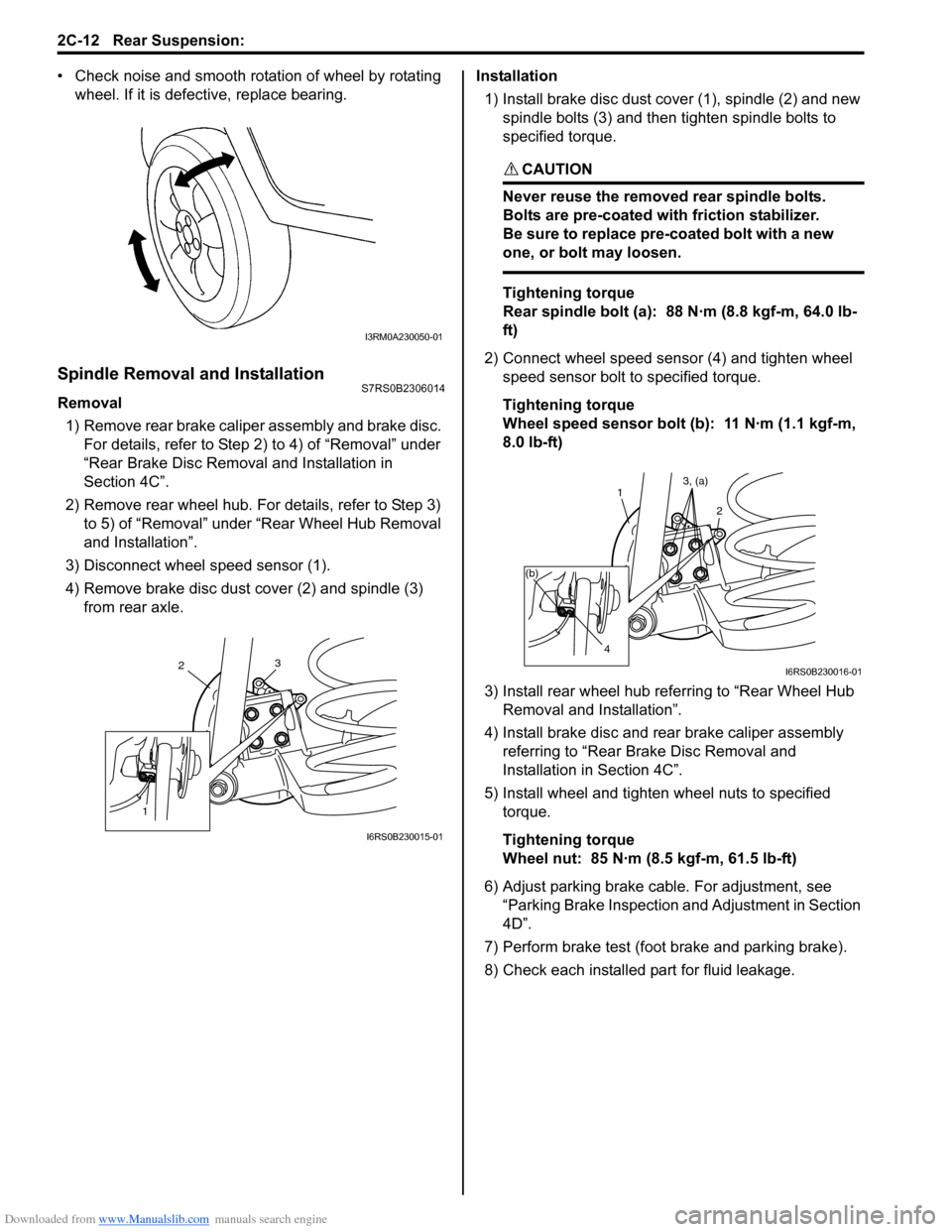
тАв Check noise and smooth rotation of wheel by rotating wheel. If it is defect ive, replace bearing.
Spindle Removal and InstallationS7RS0B2306014
Removal
1) Remove rear brake caliper assembly and brake disc. For details, refer to Step 2) to 4) of тАЬRemovalтАЭ under
тАЬRear Brake Disc Removal and Installation in
Section 4CтАЭ.
2) Remove rear wheel hub. For details, refer to Step 3) to 5) of тАЬRemovalтАЭ under тАЬRear Wheel Hub Removal
and InstallationтАЭ.
3) Disconnect wheel speed sensor (1).
4) Remove brake disc dust cover (2) and spindle (3) from rear axle. Installation
1) Install brake disc dust cover (1), spindle (2) and new spindle bolts (3) and then tighten spindle bolts to
specified torque.
CAUTION!
Never reuse the removed rear spindle bolts.
Bolts are pre-coated wi th friction stabilizer.
Be sure to replace pre-coated bolt with a new
one, or bolt may loosen.
Tightening torque
Rear spindle bolt (a): 88 N┬╖m (8.8 kgf-m, 64.0 lb-
ft)
2) Connect wheel speed sensor (4) and tighten wheel speed sensor bolt to specified torque.
Tightening torque
Wheel speed sensor bolt (b): 11 N┬╖m (1.1 kgf-m,
8.0 lb-ft)
3) Install rear wheel hub re ferring to тАЬRear Wheel Hub
Removal and InstallationтАЭ.
4) Install brake disc and rear brake caliper assembly referring to тАЬRear Brake Disc Removal and
Installation in Section 4CтАЭ.
5) Install wheel and tighten wheel nuts to specified torque.
Tightening torque
Wheel nut: 85 N┬╖m (8.5 kgf-m, 61.5 lb-ft)
6) Adjust parking brake cable. For adjustment, see тАЬParking Brake Inspection and Adjustment in Section
4DтАЭ.
7) Perform brake test (foot brake and parking brake).
8) Check each installed part for fluid leakage.
I3RM0A230050-01
2
1 3
I6RS0B230015-01
1
(b)
4
2
3, (a)
I6RS0B230016-01
Page 467 of 1496
Downloaded from www.Manualslib.com manuals search engine Rear Suspension: 2C-13
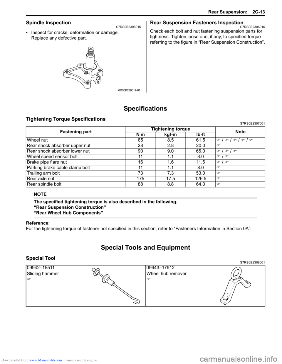
Spindle InspectionS7RS0B2306015
тАв Inspect for cracks, deformation or damage.Replace any defective part.
Rear Suspension Fasteners InspectionS7RS0B2306016
Check each bolt and nut fastening suspension parts for
tightness. Tighten loose one, if any, to specified torque
referring to the figure in тАЬRear Suspension ConstructionтАЭ.
Specifications
Tightening Torque SpecificationsS7RS0B2307001
NOTE
The specified tightening torque is also described in the following.
тАЬRear Suspension ConstructionтАЭ
тАЬRear Wheel Hub ComponentsтАЭ
Reference:
For the tightening torque of fastener not specified in this section, refer to тАЬFasteners Information in Section 0AтАЭ.
Special Tools and Equipment
Special ToolS7RS0B2308001
I6RS0B230017-01
Fastening part Tightening torque
Note
N тЛЕmkgf-mlb-ft
Wheel nut 85 8.5 61.5 �) / �) / �) / �) / �)
Rear shock absorber upper nut 28 2.8 20.0 �)
Rear shock absorber lower nut 90 9.0 65.0 �) / �) / �)
Wheel speed sensor bolt 11 1.1 8.0 �) / �)
Brake pipe flare nut 16 1.6 11.5 �) / �)
Parking brake cable clamp bolt 11 1.1 8.0 �)
Trailing arm bolt 73 7.3 53.0 �)
Rear axle nut 175 17.5 126.5 �)
Rear spindle bolt 88 8.8 64.0 �)
09942тАУ1551109943тАУ17912
Sliding hammer Wheel hub remover
�)�)
Page 497 of 1496
Downloaded from www.Manualslib.com manuals search engine Table of Contents 4-iii
ABS Warning Lamp Check ............................... 4F-14
EBD Warning Lamp (Brake Warning Lamp) Check .............................................................. 4F-15
DTC Check ....................................................... 4F-15
DTC Table ......................................................... 4F-15
DTC Clearance ................................................. 4F-18
Fail-Safe Table ................ .................................. 4F-19
Scan Tool Data ................................................. 4F-20
Visual Inspection ............................................... 4F-21
ESP ┬о Warning Lamp Does Not Come ON at
Ignition Switch ON .......................................... 4F-21
ESP ┬о Warning Lamp Comes ON Steady......... 4F-22
ABS Warning Lamp Does Not Come ON at Ignition Switch ON .......................................... 4F-23
ABS Warning Lamp Comes ON Steady............ 4F-24
EBD Warning Lamp (Brake Warning Lamp) Comes ON Steady .......................................... 4F-24
Serial Data Link Circuit Check .......................... 4F-26
DTC C1016: Stop Lamp Swit ch Circuit Failure .. 4F-28
DTC C1017 / C1023: Yaw Rate / G Sensor Assembly Failure ............................................ 4F-29
DTC C1018: Brake Fluid Le vel Switch Failure .. 4F-30
DTC 1020: Master Cylinder Pressure Sensor Power Supply Failure ...................................... 4F-31
DTC C1021, C1022 / C1025, C1026 / C1031, C1032 / C1035, C1036: Wheel Speed
Sensor Circuit or Encode r Failure ................... 4F-32
DTC C1024: Steering Angle Sensor Circuit
Failure ............................................................. 4F-34
DTC C1027: ESP ┬о OFF Switch Circuit
Failure ............................................................. 4F-34
DTC C1028: Master Cylinder Pressure Sensor Circuit Failure ....... .............................. 4F-35
DTC C1034: Yaw Rate / G Sensor Assembly Power Supply Failure ...................................... 4F-36
DTC C1037: Steering Angle Sensor Power Supply Failure ................................................. 4F-37
DTC C1038: Steering Angle Sensor Detect Rolling Counter Fa ilure from ESP┬о Control
Module ............................................................ 4F-38
DTC C1039: Yaw Rate / G Sensor Assembly Internal Failure .............. .................................. 4F-39
DTC C1040: Stability Control System Function Failure .............................................. 4F-39
DTC C1041 / C1042 / C1043 / C1044 / C1045 / C1046 / C1051 / C1052 / C1053 / C1054 /
C1055 / C1056: Solenoid Circuit Failure ......... 4F-40
DTC C1057: ESP ┬о Control Module Power
Supply Circuit Failure .... .................................. 4F-41
DTC C1061: Pump Motor and/or Motor Driver Circuit Failure .................................................. 4F-42
DTC C1063: Solenoid Valve Power Supply Driver Circuit Failure ....................................... 4F-43
DTC 1071: ESP ┬о Control Module Internal
Defect.............................................................. 4F-44 DTC C1073: Lost Communication With Yaw
Rate / G Sensor Assembly .............................. 4F-45
DTC C1075 / 1076 / 1078: Sensor Calibration Incomplete.......................... ............................. 4F-46
DTC C1090: Invalid Communication with
ECM ................................................................ 4F-47
DTC C1091 / C1094: ECM Data in CAN Line Failure / Invalid Torque Control
Communication with ECM .. ............................. 4F-48
DTC U1073: Control Module Communication Bus Off ............................................................ 4F-49
DTC U1100: Lost Communication with ECM (Reception Error)............................................. 4F-50
DTC U1126: Lost Communication with Steering Angle Sensor (Reception Error)........ 4F-51
DTC U1140: Lost Communication with BCM (Reception Error)............................................. 4F-52
Repair Instructions ........... ................................. 4F-54
ESP┬о Hydraulic Unit Operation Check ............. 4F-54
Sensor Calibration............................................. 4F-54
ESP┬о Hydraulic Unit / Control Module
Assembly On-Vehicle Inspection .................... 4F-55
ESP ┬о Hydraulic
Unit / Control Module
Assembly Removal and Inst allation ................ 4F-56
Front / Rear Wheel Speed Sensor On-Vehicle Inspection ........................................................ 4F-57
Front Wheel Speed Sensor Removal and Installation ....................................................... 4F-58
Front Wheel Speed Sensor Inspection ............. 4F-59
Rear Wheel Speed Sensor Removal and Installation ....................................................... 4F-59
Rear Wheel Speed Sensor Inspection .............. 4F-60
Front Wheel Encode r On-Vehicle Inspection .... 4F-61
Front Wheel Encoder Removal and Installation ....................................................... 4F-61
Rear Wheel Encoder On-Veh icle Inspection..... 4F-61
Rear Wheel Encoder Removal and Installation ....................................................... 4F-61
Master Cylinder Pressure Sensor On-Vehicle
Inspection ........................................................ 4F-61
Yaw Rate / G Sensor Assembly On-Vehicle Inspection ........................................................ 4F-62
Yaw Rate / G Sensor Assembly Removal and Installation ....................................................... 4F-63
Yaw Rate / G Sensor Inspection ....................... 4F-64
Steering Angle Sensor On-Vehicle Inspection .. 4F-64
Steering Angle Sensor Removal and Installation ....................................................... 4F-65
Steering Angle Sensor Inspection ..................... 4F-65
ESP┬о OFF Switch Removal an d Installation .... 4F-65
ESP┬о OFF Switch Inspection ........................... 4F-65
Specifications .................... ................................. 4F-66
Tightening Torque Specifications ...................... 4F-66
Special Tools and Equipmen t ........................... 4F-66
Special Tool ...................................................... 4F-66
Page 502 of 1496
Downloaded from www.Manualslib.com manuals search engine 4A-4 Brake Control System and Diagnosis:
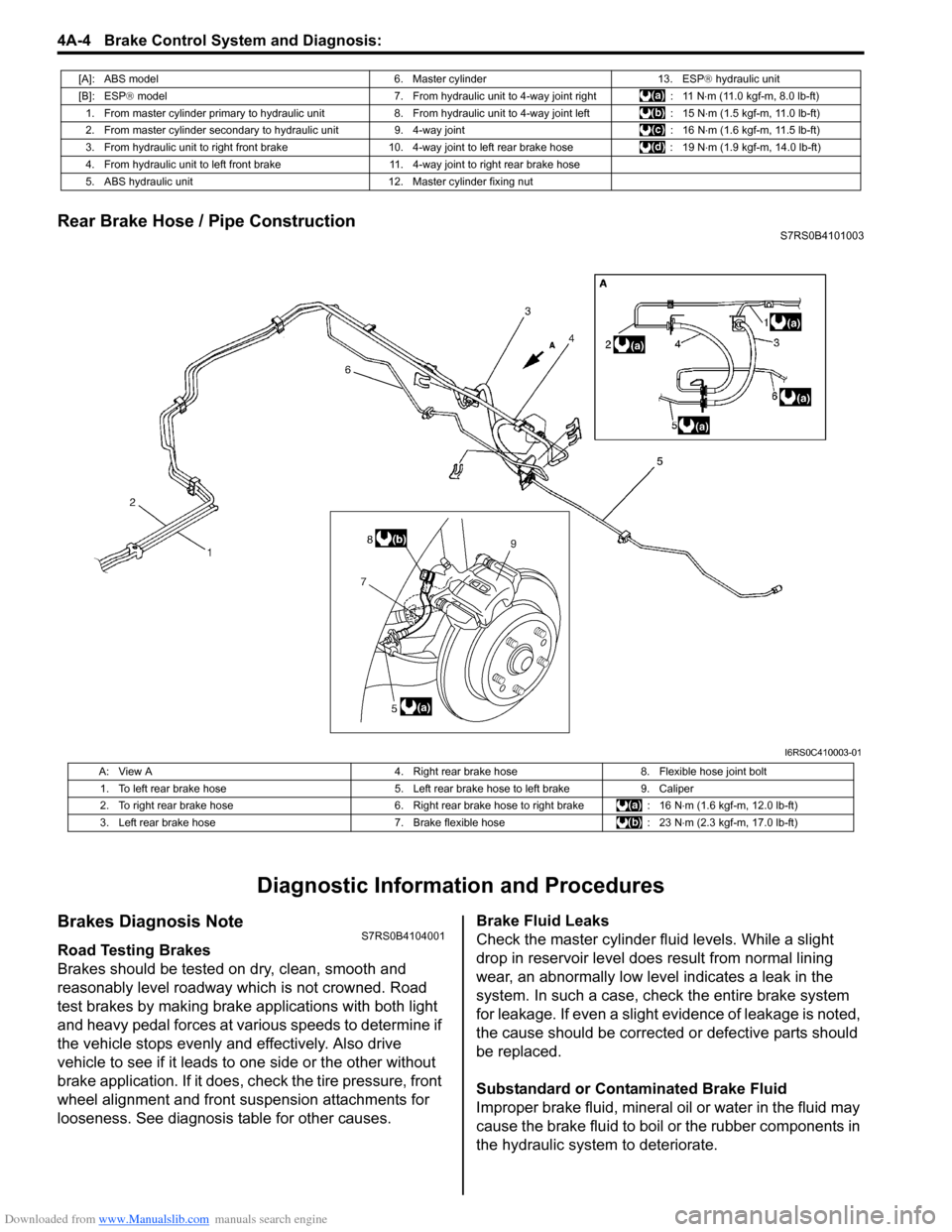
Rear Brake Hose / Pipe ConstructionS7RS0B4101003
Diagnostic Information and Procedures
Brakes Diagnosis NoteS7RS0B4104001
Road Testing Brakes
Brakes should be tested on dry, clean, smooth and
reasonably level roadway which is not crowned. Road
test brakes by making brake applications with both light
and heavy pedal forces at vari ous speeds to determine if
the vehicle stops evenly and effectively. Also drive
vehicle to see if it leads to one side or the other without
brake application. If it does, check the tire pressure, front
wheel alignment and front suspension attachments for
looseness. See diagnosis table for other causes. Brake Fluid Leaks
Check the master cylinder fl
uid levels. While a slight
drop in reservoir level does result from normal lining
wear, an abnormally low leve l indicates a leak in the
system. In such a case, chec k the entire brake system
for leakage. If even a slight ev idence of leakage is noted,
the cause should be corrected or defective parts should
be replaced.
Substandard or Contaminated Brake Fluid
Improper brake fluid, mineral oil or water in the fluid may
cause the brake fluid to boil or the rubber components in
the hydraulic system to deteriorate.
[A]: ABS model 6. Master cylinder13. ESP┬о hydraulic unit
[B]: ESP ┬о model 7. From hydraulic unit to 4-way joint right : 11 NтЛЕm (11.0 kgf-m, 8.0 lb-ft)
1. From master cylinder primary to hydraulic unit 8. From hydraulic unit to 4-way joint left: 15 NтЛЕm (1.5 kgf-m, 11.0 lb-ft)
2. From master cylinder secondary to hydraulic unit 9. 4-way joint: 16 NтЛЕm (1.6 kgf-m, 11.5 lb-ft)
3. From hydraulic unit to right front brake 10.4-way joint to left rear brake hose : 19 NтЛЕm (1.9 kgf-m, 14.0 lb-ft)
4. From hydraulic unit to left front brake 11. 4-way joint to right rear brake hose
5. ABS hydraulic unit 12. Master cylinder fixing nut
I6RS0C410003-01
A: View A4. Right rear brake hose8. Flexible hose joint bolt
1. To left rear brake hose 5. Left rear brake hose to left brake9. Caliper
2. To right rear brake hose 6. Right rear brake hose to right brake: 16 NтЛЕm (1.6 kgf-m, 12.0 lb-ft)
3. Left rear brake hose 7. Brake flexible hose: 23 NтЛЕm (2.3 kgf-m, 17.0 lb-ft)
Page 505 of 1496
Downloaded from www.Manualslib.com manuals search engine Brake Control System and Diagnosis: 4A-7
Repair Instructions
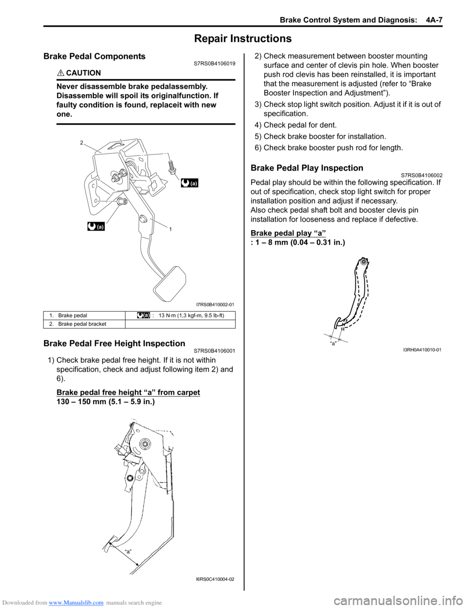
Brake Pedal ComponentsS7RS0B4106019
CAUTION!
Never disassemble brake pedalassembly.
Disassemble will spoil its originalfunction. If
faulty condition is found, replaceit with new
one.
Brake Pedal Free Height InspectionS7RS0B4106001
1) Check brake pedal free height. If it is not within specification, check and ad just following item 2) and
6).
Brake pedal free height тАЬaтАЭ from carpet
130 тАУ 150 mm (5.1 тАУ 5.9 in.) 2) Check measurement between booster mounting
surface and center of clevis pin hole. When booster
push rod clevis has been reinstalled, it is important
that the measurement is adj usted (refer to тАЬBrake
Booster Inspection and AdjustmentтАЭ).
3) Check stop light switch position . Adjust it if it is out of
specification.
4) Check pedal for dent.
5) Check brake booster for installation.
6) Check brake booster push rod for length.
Brake Pedal Play InspectionS7RS0B4106002
Pedal play should be within the following specification. If
out of specification, check stop light switch for proper
installation position and adjust if necessary.
Also check pedal shaft bolt and booster clevis pin
installation for looseness and replace if defective.
Brake pedal play
тАЬaтАЭ
: 1 тАУ 8 mm (0.04 тАУ 0.31 in.)
1. Brake pedal : 13 NтЛЕm (1,3 kgf-m, 9.5 lb-ft)
2. Brake pedal bracket
(a) 1
2
(a)
I7RS0B410002-01
I6RS0C410004-02
тАЬaтАЭI3RH0A410010-01
Page 509 of 1496
Downloaded from www.Manualslib.com manuals search engine Brake Control System and Diagnosis: 4A-11
Brake Hose and Pipe InspectionS7RS0B4106009
Hose
The brake hose assembly should be checked for road
hazard damage, for cracks and chafing of outer cover,
for leaks and blisters. A light and mirror may be needed
for an adequate inspection. If any above conditions are
observed on brake hose, it is necessary to replace it.
Pipe
Inspect the pipe for damage, cracks, dents and
corrosion. If any defect is found, replace it.
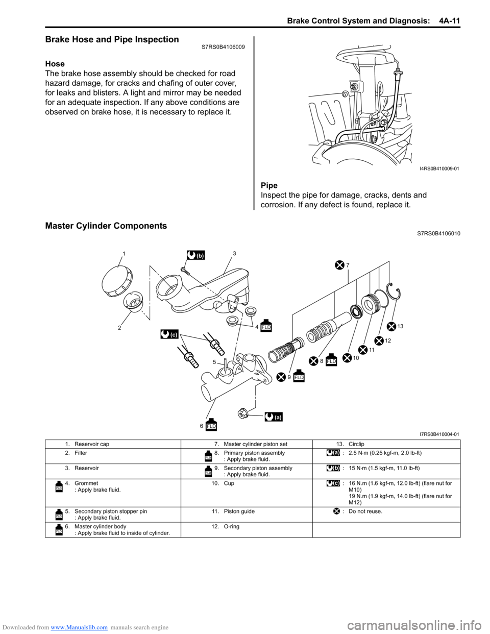
Master Cylinder ComponentsS7RS0B4106010
I4RS0B410009-01
10
11
1
2 3
4
5 7
13
12
9
FLD
8FLD
6FLD
(b)
(a)
(c)FLD
I7RS0B410004-01
1. Reservoir cap 7. Master cylinder piston set13. Circlip
2. Filter 8. Primary piston assembly
: Apply brake fluid. :2.5 N
тЛЕm (0.25 kgf-m, 2.0 lb-ft)
3. Reservoir 9. Secondary piston assembly
: Apply brake fluid. : 15 N
тЛЕm (1.5 kgf-m, 11.0 lb-ft)
4. Grommet : Apply brake fluid. 10. Cup
: 16 N.m (1.6 kgf-m, 12.0 lb-ft) (flare nut for
M10)
19 N.m (1.9 kgf-m, 14.0 lb-ft) (flare nut for
M12)
5. Secondary piston stopper pin : Apply brake fluid. 11. Piston guide
: Do not reuse.
6. Master cylinder body : Apply brake fluid to inside of cylinder. 12. O-ring
Page 514 of 1496
Downloaded from www.Manualslib.com manuals search engine 4A-16 Brake Control System and Diagnosis:
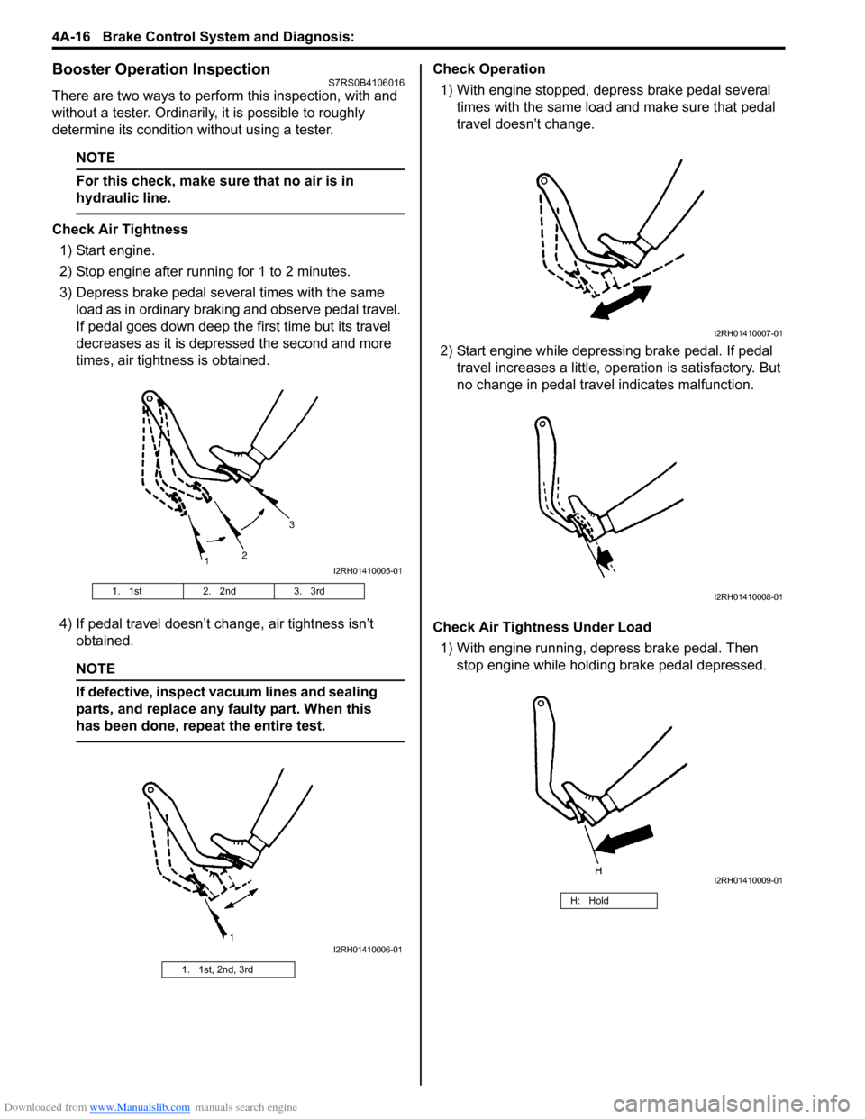
Booster Operation InspectionS7RS0B4106016
There are two ways to perform this inspection, with and
without a tester. Ordinarily, it is possible to roughly
determine its condition without using a tester.
NOTE
For this check, make su re that no air is in
hydraulic line.
Check Air Tightness
1) Start engine.
2) Stop engine after running for 1 to 2 minutes.
3) Depress brake pedal several times with the same load as in ordinary braking and observe pedal travel.
If pedal goes down deep the first time but its travel
decreases as it is depressed the second and more
times, air tightness is obtained.
4) If pedal travel doesnтАЩt change, air tightness isnтАЩt obtained.
NOTE
If defective, inspect vacuum lines and sealing
parts, and replace any faulty part. When this
has been done, repeat the entire test.
Check Operation
1) With engine stopped, depress brake pedal several times with the same load and make sure that pedal
travel doesnтАЩt change.
2) Start engine while depressing brake pedal. If pedal travel increases a little, operation is satisfactory. But
no change in pedal travel indicates malfunction.
Check Air Tightness Under Load 1) With engine running, depress brake pedal. Then stop engine while holding brake pedal depressed.
1. 1st 2. 2nd3. 3rd
1. 1st, 2nd, 3rd
I2RH01410005-01
I2RH01410006-01
H: Hold
I2RH01410007-01
I2RH01410008-01
I2RH01410009-01
Page 522 of 1496
Downloaded from www.Manualslib.com manuals search engine 4B-6 Front Brakes:
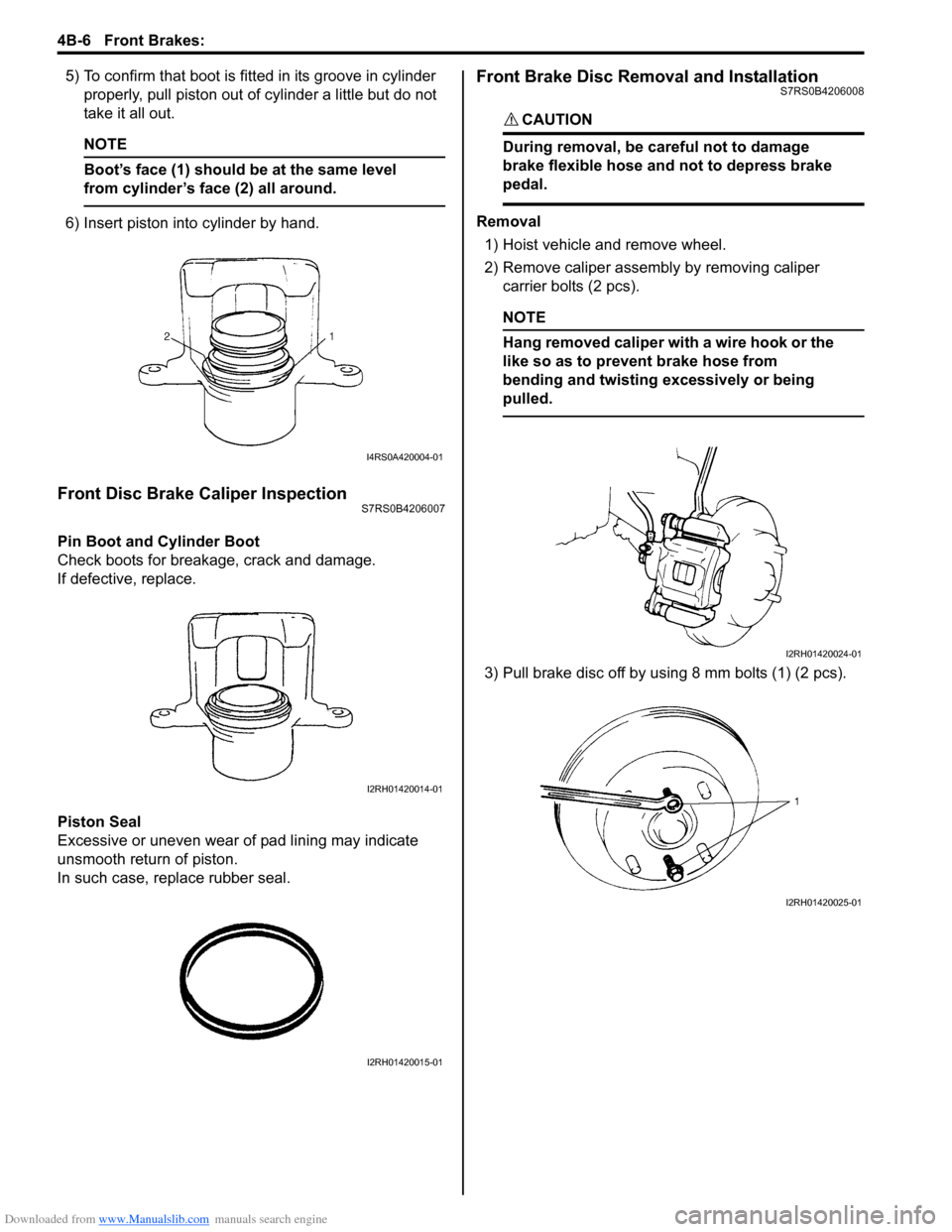
5) To confirm that boot is fitted in its groove in cylinder
properly, pull piston out of cylinder a little but do not
take it all out.
NOTE
BootтАЩs face (1) should be at the same level
from cylinderтАЩs face (2) all around.
6) Insert piston into cylinder by hand.
Front Disc Brake Caliper InspectionS7RS0B4206007
Pin Boot and Cylinder Boot
Check boots for breakage, crack and damage.
If defective, replace.
Piston Seal
Excessive or uneven wear of pad lining may indicate
unsmooth return of piston.
In such case, replace rubber seal.
Front Brake Disc Removal and InstallationS7RS0B4206008
CAUTION!
During removal, be care ful not to damage
brake flexible hose and not to depress brake
pedal.
Removal
1) Hoist vehicle and remove wheel.
2) Remove caliper assembly by removing caliper carrier bolts (2 pcs).
NOTE
Hang removed caliper with a wire hook or the
like so as to prevent brake hose from
bending and twisting excessively or being
pulled.
3) Pull brake disc off by using 8 mm bolts (1) (2 pcs).
I4RS0A420004-01
I2RH01420014-01
I2RH01420015-01
I2RH01420024-01
I2RH01420025-01
Page 532 of 1496
Downloaded from www.Manualslib.com manuals search engine 4C-8 Rear Brakes:
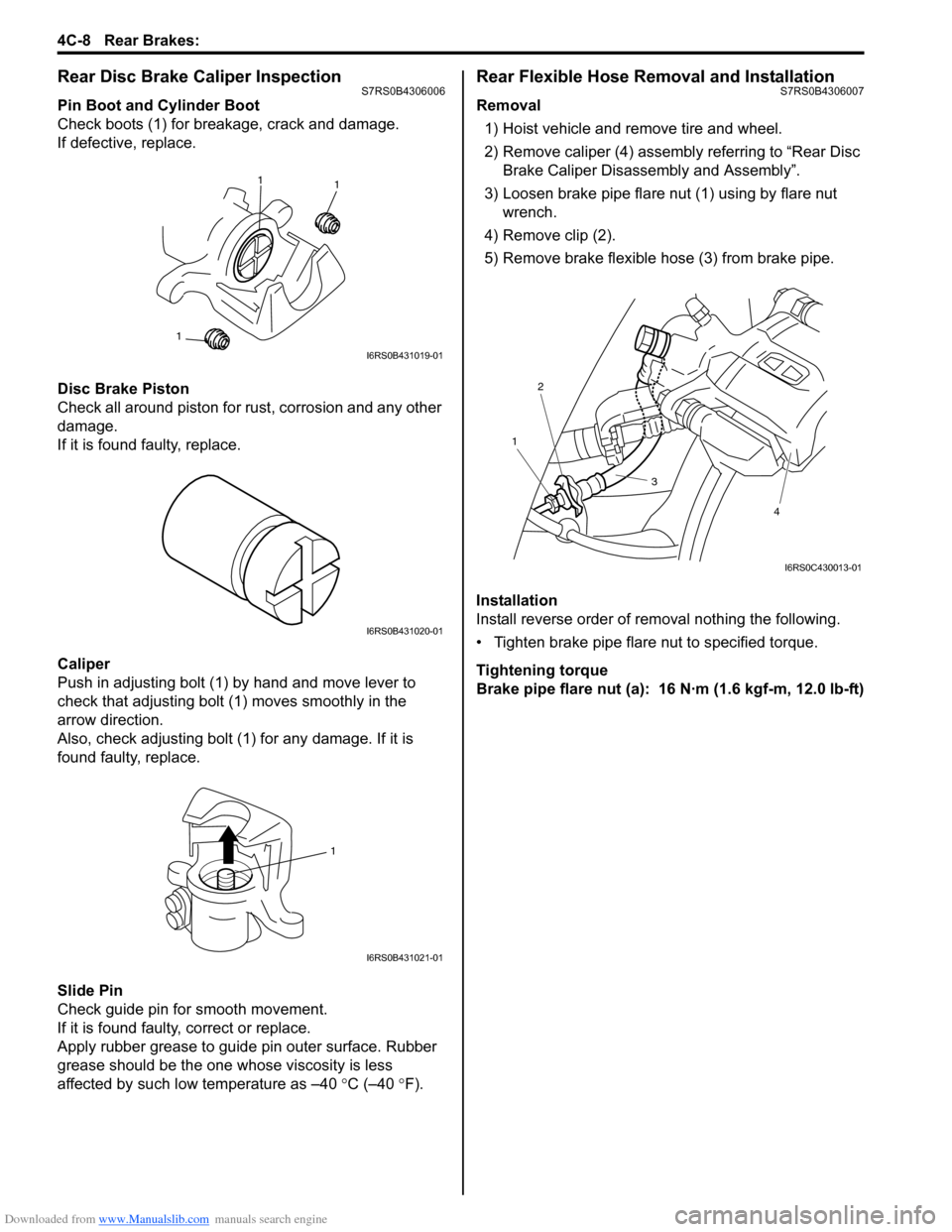
Rear Disc Brake Caliper InspectionS7RS0B4306006
Pin Boot and Cylinder Boot
Check boots (1) for breakage, crack and damage.
If defective, replace.
Disc Brake Piston
Check all around piston for rust, corrosion and any other
damage.
If it is found faulty, replace.
Caliper
Push in adjusting bolt (1) by hand and move lever to
check that adjusting bolt (1) moves smoothly in the
arrow direction.
Also, check adjusting bolt (1) for any damage. If it is
found faulty, replace.
Slide Pin
Check guide pin for smooth movement.
If it is found faulty, correct or replace.
Apply rubber grease to guide pin outer surface. Rubber
grease should be the one whose viscosity is less
affected by such low temperature as тАУ40 ┬░C (тАУ40 ┬░ F).
Rear Flexible Hose Removal and InstallationS7RS0B4306007
Removal
1) Hoist vehicle and remove tire and wheel.
2) Remove caliper (4) assembly referring to тАЬRear Disc Brake Caliper Disassembly and AssemblyтАЭ.
3) Loosen brake pipe flare nut (1) using by flare nut wrench.
4) Remove clip (2).
5) Remove brake flexible hose (3) from brake pipe.
Installation
Install reverse order of removal nothing the following.
тАв Tighten brake pipe flare nut to specified torque.
Tightening torque
Brake pipe flare nut (a): 16 N┬╖m (1.6 kgf-m, 12.0 lb-ft)
1 1
1
I6RS0B431019-01
I6RS0B431020-01
1
I6RS0B431021-01
1
2
3
4
I6RS0C430013-01