Lock SUZUKI SWIFT 2007 2.G Service Workshop Manual
[x] Cancel search | Manufacturer: SUZUKI, Model Year: 2007, Model line: SWIFT, Model: SUZUKI SWIFT 2007 2.GPages: 1496, PDF Size: 34.44 MB
Page 1025 of 1496
Downloaded from www.Manualslib.com manuals search engine Air Conditioning System: Automatic Type 7B-77
HVAC Control Module Removal and InstallationS7RS0B7226013
Removal1) Disconnect negative (–) cable at battery.
2) Disable air bag system referring to “Disabling Air Bag System in Section 8B”.
3) Remove passenger air bag module from instrument panel referring to “Passenger Air Bag (Inflator)
Module Removal and Installation in Section 8B”.
4) Remove radio assembly from instrument panel referring to “Rear Speaker Removal and Installation
in Section 9C”.
5) Remove two connectors fr om HVAC control module.
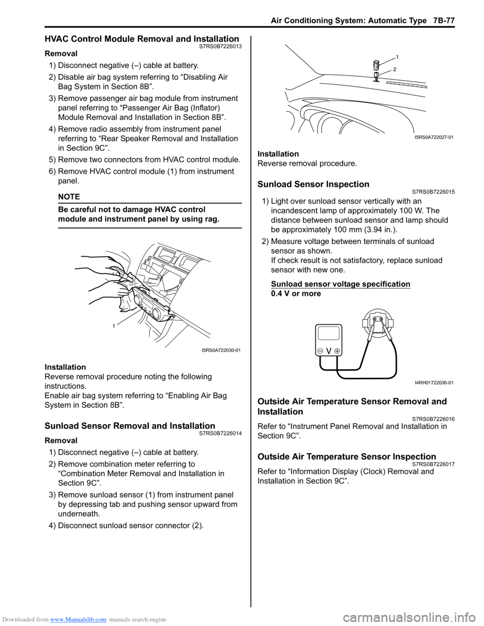
6) Remove HVAC control modu le (1) from instrument
panel.
NOTE
Be careful not to damage HVAC control
module and instrument panel by using rag.
Installation
Reverse removal procedure noting the following
instructions.
Enable air bag system referring to “Enabling Air Bag
System in Section 8B”.
Sunload Sensor Removal and InstallationS7RS0B7226014
Removal
1) Disconnect negative (–) cable at battery.
2) Remove combination meter referring to “Combination Meter Removal and Installation in
Section 9C”.
3) Remove sunload sensor (1) from instrument panel by depressing tab and pushing sensor upward from
underneath.
4) Disconnect sunload sensor connector (2). Installation
Reverse removal procedure.
Sunload Sensor InspectionS7RS0B7226015
1) Light over sunload sensor vertically with an
incandescent lamp of approximately 100 W. The
distance between sunload sensor and lamp should
be approximately 100 mm (3.94 in.).
2) Measure voltage between terminals of sunload sensor as shown.
If check result is not satisfactory, replace sunload
sensor with new one.
Sunload sensor voltage specification
0.4 V or more
Outside Air Temperature Sensor Removal and
Installation
S7RS0B7226016
Refer to “Instrument Panel Re moval and Installation in
Section 9C”.
Outside Air Temperature Sensor InspectionS7RS0B7226017
Refer to “Information Display (Clock) Removal and
Installation in Section 9C”.
1
I5RS0A722030-01
1
2
I5RS0A722027-01
I4RH01722036-01
Page 1026 of 1496
Downloaded from www.Manualslib.com manuals search engine 7B-78 Air Conditioning System: Automatic Type
Inside Air Temperature Sensor Removal and
Installation
S7RS0B7226018
Removal1) Disconnect negative (–) cable at battery.
2) Remove steering column hole cover.
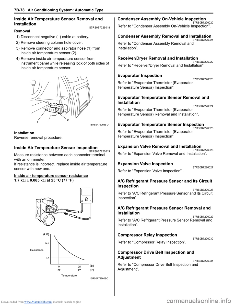
3) Remove connector and aspirator hose (1) from inside air temperature sensor (2).
4) Remove inside air temperature sensor from instrument panel while releas ing lock of both sides of
inside air temperature sensor.
Installation
Reverse removal procedure.
Inside Air Temperature Sensor InspectionS7RS0B7226019
Measure resistance between each connector terminal
with an ohmmeter.
If resistance is incorrect, replace inside air temperature
sensor with new one.
Inside air temperature sensor resistance
1.7 k Ω ± 0.085 k Ω at 25 °C (77 ° F)
Condenser Assembly On-Vehicle InspectionS7RS0B7226020
Refer to “Condenser Assembly On-Vehicle Inspection”.
Condenser Assembly Removal and InstallationS7RS0B7226021
Refer to “Condenser Assembly Removal and
Installation”.
Receiver/Dryer Removal and InstallationS7RS0B7226022
Refer to “Receiver/Dryer Removal and Installation”.
Evaporator InspectionS7RS0B7226023
Refer to “Evaporator Thermistor (Evaporator
Temperature Sensor) Inspection”.
Evaporator Temperature Sensor Removal and
Installation
S7RS0B7226024
Refer to “Evaporator Thermistor (Evaporator
Temperature Sensor) Removal and Installation”.
Evaporator Temperature Sensor InspectionS7RS0B7226025
Refer to “Evaporator Thermistor (Evaporator
Temperature Sensor) Inspection”.
Expansion Valve Removal and InstallationS7RS0B7226026
Refer to “Expansion Valve Removal and Installation”.
Expansion Valve InspectionS7RS0B7226027
Refer to “Expansion Valve Inspection”.
A/C Refrigerant Pressure Sensor and Its Circuit
Inspection
S7RS0B7226028
Refer to “A/C Refrigerant Pressure Sensor and Its Circuit
Inspection”.
A/C Refrigerant Pressure Sensor Removal and
Installation
S7RS0B7226029
Refer to “A/C Refrigerant Pressure Sensor Removal and
Installation”.
Compressor Relay InspectionS7RS0B7226030
Refer to “Compressor Relay Inspection”.
Compressor Drive Belt Inspection and
Adjustment
S7RS0B7226031
Refer to “Compressor Drive Belt Inspection and
Adjustment”.
12I5RS0A722028-01
Temperature
Resistance
1.7
0
32 25
77
F
5.5
I5RS0A722029-01
Page 1032 of 1496
Downloaded from www.Manualslib.com manuals search engine 8A-1 Seat Belts:
Restraint
Seat Belts
Precautions
Precautions on Service and Diagnosis of Seat
Belt
S7RS0B8100001
WARNING!
If replacing seat belt is necessary, replace
buckle and seat belt assembly together as a
set. This is for the reason of ensuring locking
of tongue plate with buckle. If these parts are
replaced individually, such a locking
condition may become unreliable. For this
reason, SUZUKI will supply only the spare
buckle and seat belt assembly in a set part.
Before servicing or replacing seat belts, refer to the
following precautionary items.
• Seat belts should be normal relative to strap retractor and buckle portions. • Keep sharp edges and damaging objects away from
belts.
• Avoid bending or damaging any portion of belt buckle or latch plate.
• Do not bleach or dye belt webbing. (Use only mild soap and lukewarm water to clean it.)
• When installing a seat belt anchor bolt, it should be tightened by hand at first to prevent cross-threading
and then to specified torque.
• Do not attempt any repair s on retractor mechanisms
or retractor covers. Replace defective assemblies with
new replacement parts.
• Keep belts dry and clean at all times.
• If there exist any parts in question, replace such parts.
• Replace belts whose webbing is cut or otherwise damaged.
• Do not put anything into trim panel opening which seat belt webbing passes through.
General Description
Seat Belt ConstructionS7RS0B8101001
1
1
6
6
6
5
5
7
6
6
2
2
3
4
I4RS0A810001-02
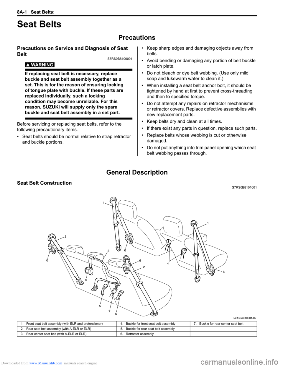
1. Front seat belt assembly (with ELR and pretensioner) 4. Buckle for front seat belt assembly7. Buckle for rear center seat belt
2. Rear seat belt assembly (with A-ELR or ELR) 5. Buckle for rear seat belt assembly
3. Rear center seat belt (with A-ELR or ELR) 6. Retractor assembly
Page 1033 of 1496
Downloaded from www.Manualslib.com manuals search engine Seat Belts: 8A-2
Seat Belt with ELR
The seat belt with emergency locking retractor (ELR) is
designed so that it locks immediately (to prevent the
webbing from being pulled out of the retractor any
further) when any of the following items is detected as
exceeding each set value;
• Speed at which the webbing is pulled out of the retractor.
• Acceleration or deceleration of the vehicle speed.
• Inclination.
Seat Belt with A-ELR
The automatic and emergency locking retractor (A-ELR)
works as an Emergency Locking Retractor (ELR) till its
webbing is pulled all the way out and then on as an
Automatic Locking Retractor (ALR ) till it is retracted fully.
ALR: Automatically locks when the webbing is pulled out
from the retractor and allowed to retract even a little.
Then the webbing can not be pulled out any further,
unless it is wound all the way back into the retractor,
which releases the lock and allows the webbing to be
pulled out.
Seat Belt with ELR and Pretensioner
The seat belt with ELR and a pretensioner has a
pretensioner mechanism whic h operates in linkage with
the air bag in addition to the described ELR.
The pretensioner is incorporated in retractor assembly
and controlled by SDM as one of air bag system
components. It will be activated at the same time as the
driver and passenger air bag module when an impact at
the front of vehicle exceeds the specified value.
When servicing seat belt (retractor assembly) with
pretensioner, be sure to observe all WARNINGS and
CAUTIONS and “Precautions on Service and Diagnosis
of Air Bag System in Section 8B”. CAUTION!
Do not reuse the seat belt pretensioner
(retractor assembly) that has activated.
Replace it with a new seat belt assembly and
buckle together as a set. For checking
procedure of its activation, refer to “Repair
and Inspection Required after Accident in
Section 8B”.
Seat Belt Remainder
When driver’s seat belt is unfastened (under the
following conditions), seat belt reminder light and
warning buzzer inform that driver’s seat belt is
unfastened. Seat belt reminder light located in
combination meter and warning buzzer located inside
BCM operate as follows:
• Seat belt reminder light comes on when driver’s seat belt is unfastened while igni tion key switch is at ON
position.
• If vehicle speed exceeds 15 km/h with seat belt unfastened, warning buzzer operates for
approximately 95 seconds and seat belt reminder light
flashes synchronously with buzzer. When warning
buzzer stops operating, seat belt reminder light is
turned on.
• If driver’s seat belt state is changed from “fastened” to “unfastened” while vehicle speed is above 15 km/h,
warning buzzer operates for approximately 95
seconds and seat belt reminder light flashes
synchronously with buzzer. When warning buzzer
stops operating, seat belt reminder light is turned on.
Diagnostic Information and Procedures
Repair and Inspection Required after AccidentS7RS0B8104001
After an accident, whether the seat belt pretensioner has been activated or not, be sure to perform checks and repairs
described on “Repair and Inspection Required after Accident in Section 8B”.
Page 1035 of 1496
Downloaded from www.Manualslib.com manuals search engine Seat Belts: 8A-4
Front Seat Belt Removal and InstallationS7RS0B8106002
WARNING!
• Never attempt to disassemble or repair the seat belt pretensioner (retractor
assembly). If any abnormality is found, be
sure to replace it with new one as an
assembly.
• Be sure to read “Precautions on Service and Diagnosis of Seat Belt” before starting
to work and observe every precaution
during work. Ne glecting them may result in
personal injury or una ctivation of the seat
belt pretensioner when necessary.
Removal
1) Disconnect negative (–) cable at battery.
2) Disable air bag system. Refer to “Disabling Air Bag System in Section 8B”.
3) Remove center pillar lower trim.
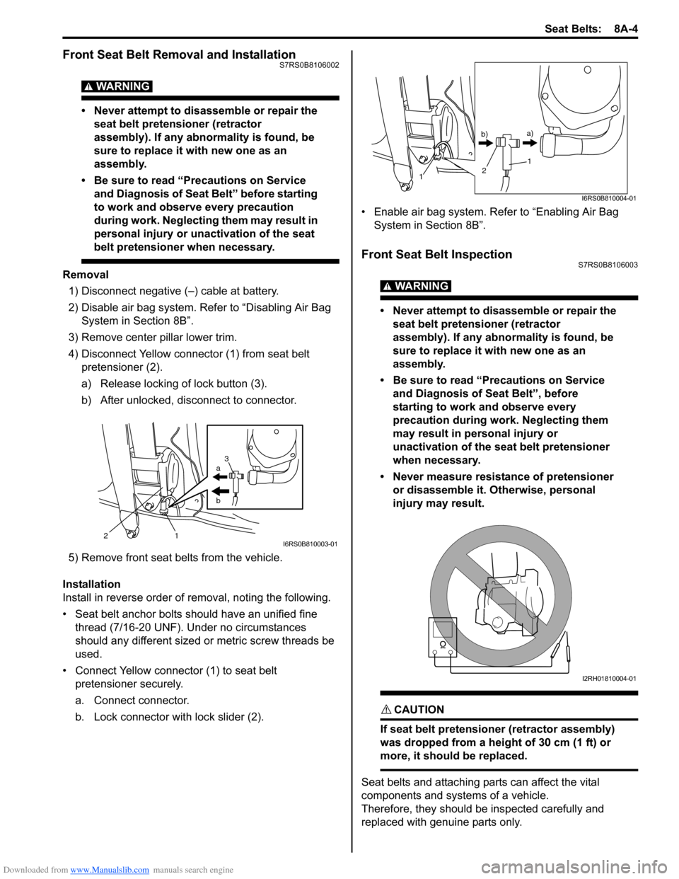
4) Disconnect Yellow connector (1) from seat belt pretensioner (2).
a) Release locking of lock button (3).
b) After unlocked, disconnect to connector.
5) Remove front seat belts from the vehicle.
Installation
Install in reverse order of removal, noting the following.
• Seat belt anchor bolts should have an unified fine thread (7/16-20 UNF). Under no circumstances
should any different sized or metric screw threads be
used.
• Connect Yellow connector (1) to seat belt pretensioner securely.
a. Connect connector.
b. Lock connector with lock slider (2). • Enable air bag system. Refer to “Enabling Air Bag
System in Section 8B”.
Front Seat Belt InspectionS7RS0B8106003
WARNING!
• Never attempt to disassemble or repair the seat belt pretensioner (retractor
assembly). If any abnormality is found, be
sure to replace it with new one as an
assembly.
• Be sure to read “Precautions on Service and Diagnosis of Seat Belt”, before
starting to work and observe every
precaution during work. Neglecting them
may result in personal injury or
unactivation of the seat belt pretensioner
when necessary.
• Never measure resistance of pretensioner or disassemble it. Otherwise, personal
injury may result.
CAUTION!
If seat belt pretensioner (retractor assembly)
was dropped from a height of 30 cm (1 ft) or
more, it should be replaced.
Seat belts and attaching parts can affect the vital
components and systems of a vehicle.
Therefore, they should be inspected carefully and
replaced with genuine parts only.
a
b
21 3I6RS0B810003-01
1
1
2
b)
a)
I6RS0B810004-01
I2RH01810004-01
Page 1036 of 1496
Downloaded from www.Manualslib.com manuals search engine 8A-5 Seat Belts:
Seat Belt
• The seat belt webbing or strap should be free from damage.
Retractor Assembly (with Seat Belt Pretensioner) 1) Let the seat belt retract fully to confirm its easy retraction.
• The retractor assembly should lock webbing when
pulled quickly.
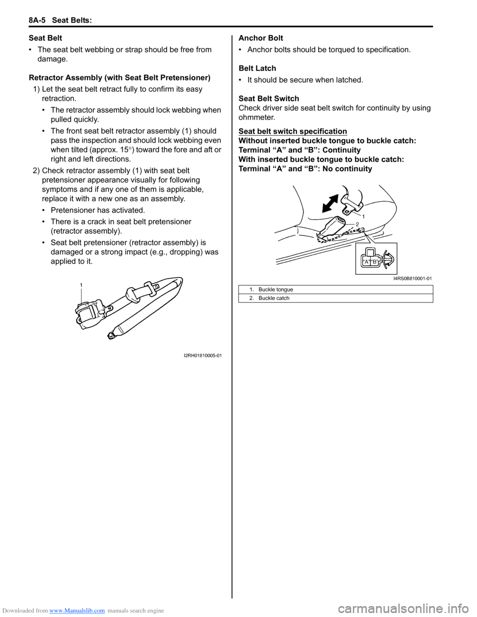
• The front seat belt retractor assembly (1) should pass the inspection and should lock webbing even
when tilted (approx. 15 °) toward the fore and aft or
right and left directions.
2) Check retractor assembly (1) with seat belt pretensioner appearance visually for following
symptoms and if any one of them is applicable,
replace it with a new one as an assembly.
• Pretensioner has activated.
• There is a crack in seat belt pretensioner (retractor assembly).
• Seat belt pretensioner (retractor assembly) is damaged or a strong impact (e.g., dropping) was
applied to it. Anchor Bolt
• Anchor bolts should be torqued to specification.
Belt Latch
• It should be secure when latched.
Seat Belt Switch
Check driver side seat belt s
witch for continuity by using
ohmmeter.
Seat belt switch specification
Without inserted buckle tongue to buckle catch:
Terminal “A” and “B”: Continuity
With inserted buckle tongue to buckle catch:
Terminal “A” and “B”: No continuity
I2RH01810005-01
1. Buckle tongue
2. Buckle catch
I4RS0B810001-01
Page 1038 of 1496
Downloaded from www.Manualslib.com manuals search engine 8A-7 Seat Belts:
Rear Seat Belt Removal and InstallationS7RS0B8106005
WARNING!
Be sure to read “Precautions on Service and
Diagnosis of Seat Belt” before starting to
work and observe every precaution during
work.
Removal1) Fold rear seats referring to “Folding Rear Seats” in Owners Manual.
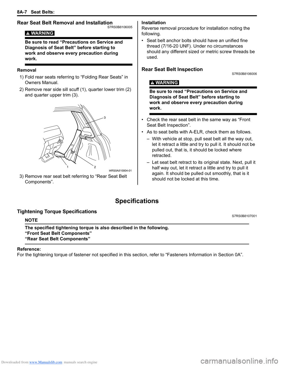
2) Remove rear side sill scuff (1), quarter lower trim (2)
and quarter upper trim (3).
3) Remove rear seat belt referring to “Rear Seat Belt Components”. Installation
Reverse removal procedure for installation noting the
following.
• Seat belt anchor bolts should have an unified fine
thread (7/16-20 UNF). Under no circumstances
should any different sized or metric screw threads be
used.Rear Seat Belt InspectionS7RS0B8106006
WARNING!
Be sure to read “Precautions on Service and
Diagnosis of Seat Belt” before starting to
work and observe every precaution during
work.
• Check the rear seat belt in the same way as “Front Seat Belt Inspection”.
• As to seat belts with A-ELR, check them as follows. – With vehicle at stop, pull seat belt all the way out, let it retract a little and try to pull it. It should not be
pulled out, that is, it should be locked where
retracted.
– Let seat belt retract to its original state. Next, pull it
half way out, let it retrac t a little and try to pull it
again. It should be pulled out smoothly, that is it
should not be locked at this time.
Specifications
Tightening Torque SpecificationsS7RS0B8107001
NOTE
The specified tightening torque is also described in the following.
“Front Seat Belt Components”
“Rear Seat Belt Components”
Reference:
For the tightening torque of fastener not specified in this section, refer to “Fasteners Information in Section 0A”.
3
2
1
I4RS0A810004-01
Page 1045 of 1496
![SUZUKI SWIFT 2007 2.G Service Workshop Manual Downloaded from www.Manualslib.com manuals search engine Air Bag System: 8B-7
Schematic and Routing Diagram
Air Bag System Wiring Circuit DiagramS7RS0B8202001
[A]
[B]“E13” “E44”, “G04� SUZUKI SWIFT 2007 2.G Service Workshop Manual Downloaded from www.Manualslib.com manuals search engine Air Bag System: 8B-7
Schematic and Routing Diagram
Air Bag System Wiring Circuit DiagramS7RS0B8202001
[A]
[B]“E13” “E44”, “G04�](/img/20/7607/w960_7607-1044.png)
Downloaded from www.Manualslib.com manuals search engine Air Bag System: 8B-7
Schematic and Routing Diagram
Air Bag System Wiring Circuit DiagramS7RS0B8202001
[A]
[B]“E13” “E44”, “G04” “G35” and "L03" \
"L41"
1
2 GRN/RED
GRN GRN/RED
GRN
BLU/RED YEL/RED BLU/RED
YEL/RED
GRN/ORN GRN/YEL
RED
13
PPL/WHT
9 7
8
5
6
10 “L10”
“L11”
“L04”
“G35” “G34”
“G33”
“G28”
“G32”
“L35”
L29-2
L29-27
L29-32 L29-5
L29-6 L29-4
L29-3
L29-8
L29-7
IG
ST
YEL L29-37ADS
WHT/RED
LT GRN/BLK L29-46
L29-47 SD+
SD-
11
WHT/GRN LT GRN
BLK L29-45
L29-44 WL
L29-28
E1 DP-
DP+ P- P+ D- D+
“G10”
“G04”“L29”
18
BLU/ORN
BLU/YEL “L36”
L29-9
L29-10
PP-
PP+
19 17
GRY/RED
GRY
L29-12
L29-11
DS- DS+ “L25”
20
BRN/WHT
BRN
L29-13
L29-14
PS- PS+ “L30”
21
YEL/GRN
YEL/BLU
L29-20
L29-19
DC- DC+ “L18”
22
BLK/YEL
BRN/YEL
L29-21
L29-22
PC- PC+ “L41”
2316
15
14
“L29”
SP+
SP-
“G26”“L32”
“L03”“E44”“E13”
12
ORN
PNK/BLK
GRY/RED
GRY L29-50
L29-51 FD+
FD-
3 4
YEL/BLK
YEL/BLK
GRN RED/BLK
I7RS0A820002-03
[A]: Shorting bar
8. BCM 17. Passenger air bag (inflator) module
[B]: Connector 9. To data link connector (DLC)18. Driver seat belt pretensioner
1. To battery 10. Driver side-sensor (if equipped)19. Passenger seat belt pretensioner
2. Ignition switch 11. Passenger side-sensor (if equipped) 20. Driver side-air bag (inflator) module (if equipped)
3. “AIR BAG” warning light 12. Forward-sensor 21. Passenger side-air bag (inflator) module (if equipped)
4. Light driver 13. Ground for air bag system 22. Driver side curtain-air bag (inflator) module (if equipped)
5. “METER” fuse 14. SDM 23. Passenger side curtain-air bag (inflator) module (if equipped)
6. “A/BAG” fuse 15. Contact coil
7. Junction block assembly 16. Driver air bag (inflator) module
Page 1048 of 1496
Downloaded from www.Manualslib.com manuals search engine 8B-10 Air Bag System:
Diagnostic Information and Procedures
Air Bag Diagnostic System CheckS7RS0B8204001
WARNING!
To avoid deployment when troubleshooting
the air bag system, do not use electrical test
equipment such as a battery powered or AC
powered voltmeter, ohmmeter, etc., or any
type of electrical equipment other than that
specified in this manual. Do not use a non-
powered probe type tester.
Instructions in this manual must be followed
carefully, otherwise personal injury may
result.
CAUTION!
The order in which DTCs are diagnosed is
very important. Failure to diagnose the DTCs
in the order specified may result in extended
diagnostic time, incorrect diagnosis and
incorrect parts replacement.
The diagnostic procedures used are designed to find
and repair air bag system malfunctions.
To get the best results, it is important to use the
diagnostic flow and follow the sequence in the following.1) Perform the “Air Bag Diagnostic System Check Flow”.
(The “Air Bag Diagnostic System Check Flow” must
be the starting point of any air bag system diagnosis.
The “Air Bag Diagnostic System Check Flow” checks
for proper “AIR BAG” warning right operation
through “AIR BAG” warning right and whether air
bag DTCs exist.)
2) Refer to the proper diagnost ic flow as directed by the
“Air Bag Diagnostic System Check Flow”.
(The “Air Bag Diagnostic System Check Flow” will
lead you to the correct flow to diagnose any air bag
system malfunctions. Bypassing these procedures
may result in extended diagnostic time, incorrect
diagnosis and incorrect parts replacement.)
3) Repeat the “Air Bag Diagnostic System Check Flow” after any repair or diagnostic procedures have been
performed.
(Performing the “Air Bag Diagnostic System Check
Flow” after all repair or diagnostic procedures will
ensure that the repair has been made correctly and
that no other malfunctions exist.)
Air Bag Diagnostic System Check FlowS7RS0B8204002
Flow test description
Step 1: Check that “AIR BAG” warning right lights.
Step 2: Check that “AIR BAG” warning right lights.
Step 3: Check that “AIR BAG” warning right flas hes 6 times after ignition switch is turned ON.
Step 4: Check that history codes are in SDM memory.
Step 5: Check that current code is in SDM memory.
6. “A/BAG” fuse in junction block assembly (including BCM) 13. Side curtain-air bag (inflator) module (if equipped)
7. Air bag harness in floor harness 14. Air bag harness in instrument panel harness
Step Action YesNo
1 1) Make sure that battery voltage is about 11 V or higher.
2) Note “AIR BAG” warning right as ignition switch is turned
ON.
Does “AIR BAG” warning ri ght come ON when ignition
switch is turned ON? Go to Step 2.
Proceed to ““AIR BAG”
Warning Right Does Not
Come ON”.
2 Does “AIR BAG” warning right come ON steady? Proceed to ““AIR BAG”
Warning Right Comes
ON Steady”.Go to Step 3.
3 Does “AIR BAG” warning right turn OFF, after flashing 6
times? “AIR BAG” warning right
circuit is in good
condition. Go to Step 4.“AIR BAG” warning right
circuit is in good
condition. Go to Step 5.
Page 1051 of 1496
Downloaded from www.Manualslib.com manuals search engine Air Bag System: 8B-13
Scan Tool DataS7RS0B8204006
Data list of SDM
Definition
Back Up Volt (V)
This parameter indicates the capacity of the backup
condenser installed to maintain the ignition current (as
much as possible) even when the power supply to SDM
that ignites the inflator is shut off.
Battery Voltage (V)
Battery voltage is an analog input signal read by SDM.
System ID (4ch/8ch)
This parameter indicates the number of initiator circuits.
Driv A/B Ini Res (Driver air bag initiator resistance)
(ohm)
This parameter indicates the resistance of the driver air
bag initiator circuit. Pass A/B Ini Res (Passenger air bag initiator
resistance) (ohm)
This parameter indicates the
resistance of the passenger
air bag initiator circuit.
Driv Preten Ini Res (Dri ver pretensioner initiator
resistance) (ohm)
This parameter indicates the resistance of the driver seat
belt pretensioner initiator circuit.
Pass Preten Ini Res (Passenger pretensioner
initiator resistance) (ohm)
This parameter indicates the resistance of the passenger
seat belt pretensioner initiator circuit.
Driv Sidebag Ini Res (Driver side-air bag initiator
resistance) (ohm)
This parameter indicates the resistance of the driver
side-air bag initiator circuit.
Pass Sidebag Ini Res (Passenger side-air bag
initiator resistance) (ohm)
This parameter indicates the resistance of the
Passenger side-air bag initiator circuit.
Driv curtain Ini Res (Driver side curtain-air bag
initiator resistance) (ohm)
This parameter indicates the re sistance of the driver side
curtain-air bag initiator circuit.
Pass curtain Ini Res (Passenger side curtain-air bag
initiator resistance) (ohm)
This parameter indicates the resistance of the passenger
side curtain-air bag initiator circuit.
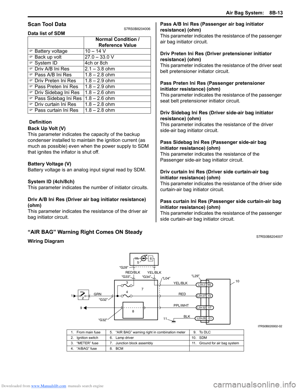
“AIR BAG” Warning Right Comes ON SteadyS7RS0B8204007
Wiring Diagram Normal Condition /
Reference Value
�) Battery voltage 10 – 14 V
�) Back up volt 27.0 – 33.0 V
�) System ID 4ch or 8ch
�) Driv A/B Ini Res 2.1 – 3.8 ohm
�) Pass A/B Ini Res 1.8 – 2.8 ohm
�) Driv Preten Ini Res 1.8 – 2.9 ohm
�) Pass Preten Ini Res 1.8 – 2.9 ohm
�) Driv Sidebag Ini Res 1.8 – 2.6 ohm
�) Pass Sidebag Ini Res 1.8 – 2.6 ohm
�) Driv curtain Ini Res 1.8 – 2.8 ohm
�) Pass curtain Ini Res 1.8 – 2.8 ohm
1
2 GRN
11
BLK
L29-27
L29-2
L29-28 WL
E1
IG
L29-32
ST
10
8
“L29”
RED
PPL/WHT
7
3
4 “L04”
“G34”
“G33”
“G28”
“G32”
5 6
“G32”
YEL/BLK
YEL/BLK
RED/BLK
9
I7RS0B820002-02
1. From main fuse 5. “AIR BAG” warning right in combination meter 9. To DLC
2. Ignition switch 6. Lamp driver 10. SDM
3. “METER” fuse 7. Junction block assembly 11. Ground for air bag system
4. “A/BAG” fuse 8. BCM