windshield SUZUKI SWIFT 2007 2.G Service Owner's Manual
[x] Cancel search | Manufacturer: SUZUKI, Model Year: 2007, Model line: SWIFT, Model: SUZUKI SWIFT 2007 2.GPages: 1496, PDF Size: 34.44 MB
Page 1324 of 1496
Downloaded from www.Manualslib.com manuals search engine 9D-7 Wipers / Washers:
Rear Wiper Motor InspectionS7RS0B9406007
NOTE
Make sure that battery voltage is 12 V or
more.
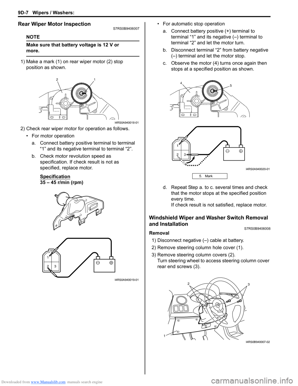
1) Make a mark (1) on rear wiper motor (2) stop position as shown.
2) Check rear wiper motor for operation as follows. • For motor operationa. Connect battery positive terminal to terminal “1” and its negative terminal to terminal “2”.
b. Check motor revolution speed as specification. If check result is not as
specified, replace motor.
Specification
35 – 45 r/min (rpm) • For automatic stop operation
a. Connect battery positive (+) terminal to terminal “1” and its negative (–) terminal to
terminal “2” and let the motor turn.
b. Disconnect terminal “2” from battery negative (–) terminal and let the motor stop.
c. Observe the motor (4) turns once again then stops at a specified position as shown.
d. Repeat Step a. to c. several times and check that the motor stops at the specified position
every time.
If check result is not satisfied, replace motor.
Windshield Wiper and Washer Switch Removal
and Installation
S7RS0B9406008
Removal
1) Disconnect negative (–) cable at battery.
2) Remove steering column hole cover (1).
3) Remove steering column covers (2). Turn steering wheel to a ccess steering column cover
rear end screws (3).
I4RS0A940018-01
1
23
I4RS0A940019-01
5. Mark
I4RS0A940020-01
1
32
I4RS0B940007-02
Page 1325 of 1496
Downloaded from www.Manualslib.com manuals search engine Wipers / Washers: 9D-8
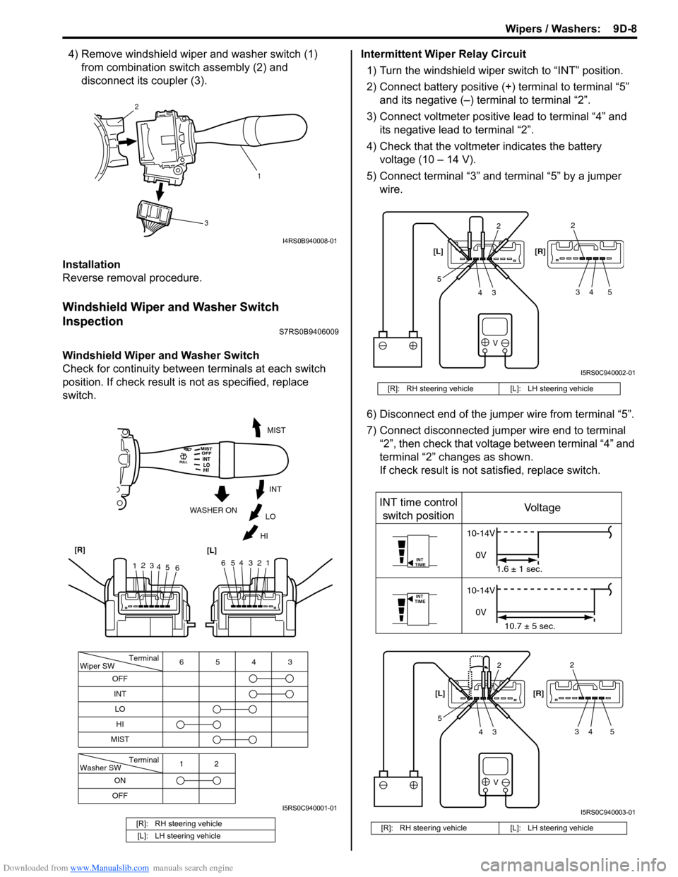
4) Remove windshield wiper and washer switch (1) from combination swit ch assembly (2) and
disconnect its coupler (3).
Installation
Reverse removal procedure.
Windshield Wiper and Washer Switch
Inspection
S7RS0B9406009
Windshield Wiper and Washer Switch
Check for continuity between terminals at each switch
position. If check result is not as specified, replace
switch. Intermittent Wiper Relay Circuit
1) Turn the windshield wiper switch to “INT” position.
2) Connect battery positive (+ ) terminal to terminal “5”
and its negative (–) terminal to terminal “2”.
3) Connect voltmeter positive lead to terminal “4” and its negative lead to terminal “2”.
4) Check that the voltmeter indicates the battery voltage (10 – 14 V).
5) Connect terminal “3” and terminal “5” by a jumper wire.
6) Disconnect end of the jumper wire from terminal “5”.
7) Connect disconnected jumper wire end to terminal “2”, then check that voltage between terminal “4” and
terminal “2” changes as shown.
If check result is not satisfied, replace switch.
[R]: RH steering vehicle
[L]: LH steering vehicle
1
2
3
I4RS0B940008-01
Terminal
Wiper SW
OFF
INT 6543
MIST
Terminal
Washer SW
OFF 12
ONLO
HI
654321
MIST
INT
LO
HI
WASHER ON
1
2
3
4 5 6
[R]
[L]
I5RS0C940001-01
[R]: RH steering vehicle [L]: LH steering vehicle
[R]: RH steering vehicle [L]: LH steering vehicle
V
2
34
52
34 5
[L] [R]
I5RS0C940002-01
V
INT
TIME
INT
TIME
INT time control
switch position Voltage
10-14V
0V 1.6 ± 1 sec.
10-14V
0V 10.7 ± 5 sec.
2
34
52
34 5
[L]
[R]
I5RS0C940003-01
Page 1326 of 1496
Downloaded from www.Manualslib.com manuals search engine 9D-9 Wipers / Washers:
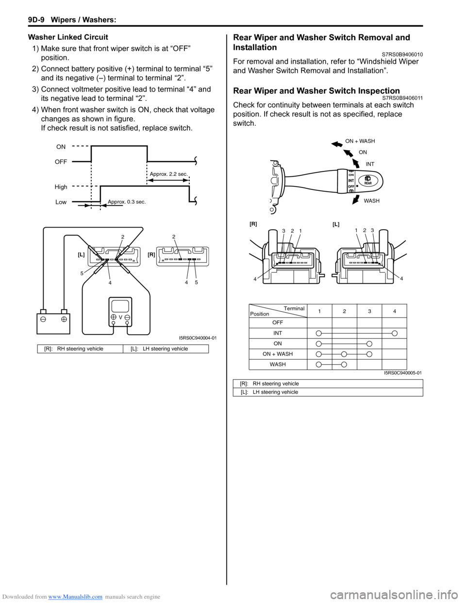
Washer Linked Circuit1) Make sure that front wiper switch is at “OFF” position.
2) Connect battery positive (+ ) terminal to terminal “5”
and its negative (–) terminal to terminal “2”.
3) Connect voltmeter positive lead to terminal “4” and its negative lead to terminal “2”.
4) When front washer switch is ON, check that voltage
changes as shown in figure.
If check result is not satisfied, replace switch.Rear Wiper and Washer Switch Removal and
Installation
S7RS0B9406010
For removal and installation, refer to “Windshield Wiper
and Washer Switch Removal and Installation”.
Rear Wiper and Washer Switch InspectionS7RS0B9406011
Check for continuity between terminals at each switch
position. If check result is not as specified, replace
switch.
[R]: RH steering vehicle [L]: LH steering vehicle
V
2
4
52
45
[L] [R]
ON
OFF
High Low
Approx. 0.3 sec. Approx. 2.2 sec.
I5RS0C940004-01
[R]: RH steering vehicle
[L]: LH steering vehicle
Terminal
Position
OFF
INT 4
3
12
WASH ON
ON + WASH
ON + WASH
INT
ON
WASH
123
4
[R]
[L]123
4
I5RS0C940005-01
Page 1327 of 1496
Downloaded from www.Manualslib.com manuals search engine Wipers / Washers: 9D-10
Rear Wiper Relay Removal and InstallationS7RS0B9406012
Removal1) Disconnect negative (–) cable at battery.
2) Remove junction block assembly referring to “BCM (Included in Junction Block Assembly) Removal and
Installation in Section 10B”.
3) Remove rear wiper relay.
Installation
Reverse removal procedure for installation.
Rear Wiper Relay InspectionS7RS0B9406013
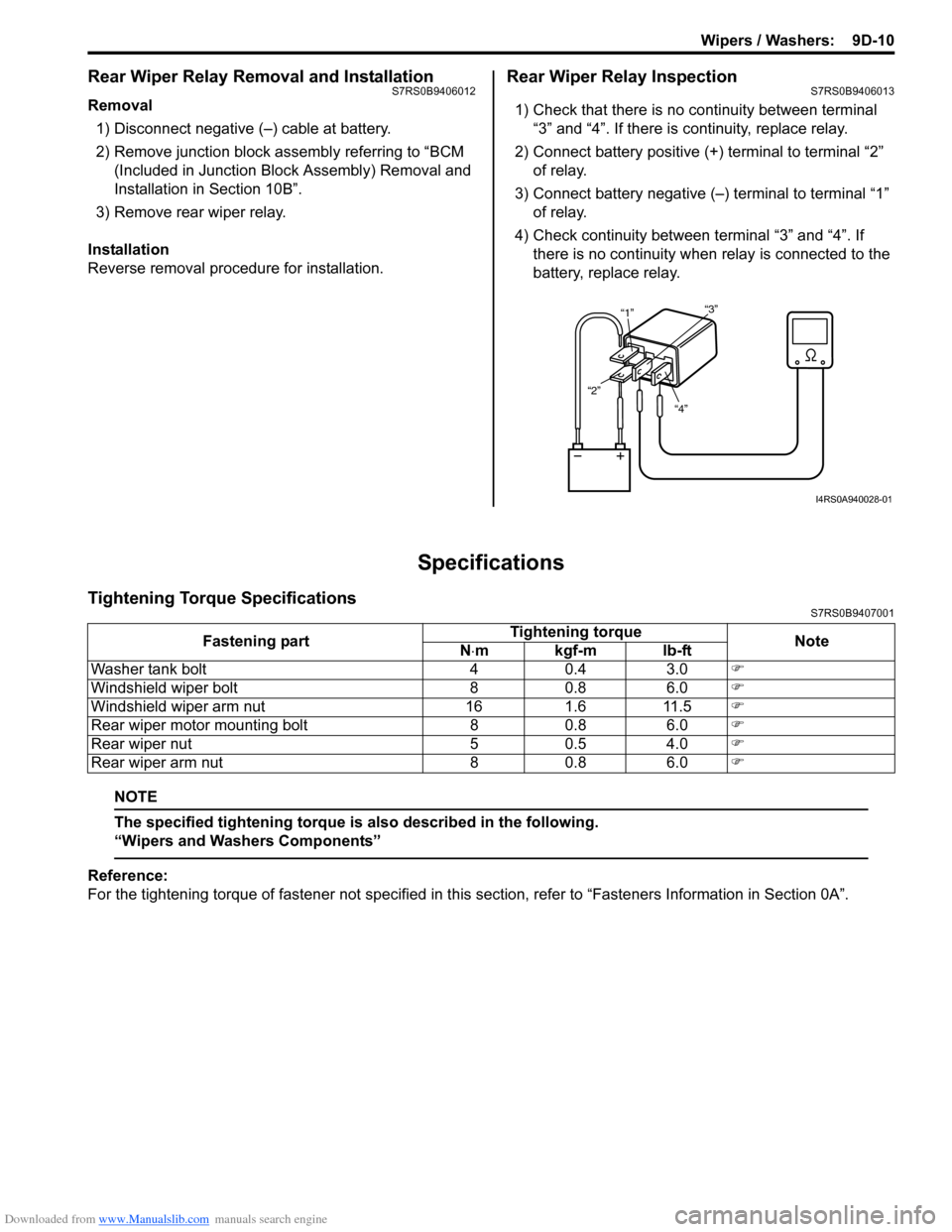
1) Check that there is no continuity between terminal “3” and “4”. If there is continuity, replace relay.
2) Connect battery positive (+ ) terminal to terminal “2”
of relay.
3) Connect battery negative (–) terminal to terminal “1” of relay.
4) Check continuity between terminal “3” and “4”. If
there is no continuity when relay is connected to the
battery, replace relay.
Specifications
Tightening Torque SpecificationsS7RS0B9407001
NOTE
The specified tightening torque is also described in the following.
“Wipers and Washers Components”
Reference:
For the tightening torque of fastener not specified in this section, refer to “Fasteners Information in Section 0A”.
“4”
“2” “1”
“3”
I4RS0A940028-01
Fastening part Tightening torque
Note
N ⋅mkgf-mlb-ft
Washer tank bolt 4 0.4 3.0 )
Windshield wiper bolt 8 0.8 6.0 )
Windshield wiper arm nut 16 1.6 11.5 )
Rear wiper motor mounting bolt 8 0.8 6.0 )
Rear wiper nut 5 0.5 4.0 )
Rear wiper arm nut 8 0.8 6.0 )
Page 1328 of 1496
Downloaded from www.Manualslib.com manuals search engine 9E-1 Glass / Windows / Mirrors:
Body, Cab and Accessories
Glass / Windows / Mirrors
General Description
Rear End Door Window Defogger System DescriptionS7RS0B9501001
The rear end door window defogger is controlled by BCM. For the BCM description refer to “BCM General Description
in Section 10B”.
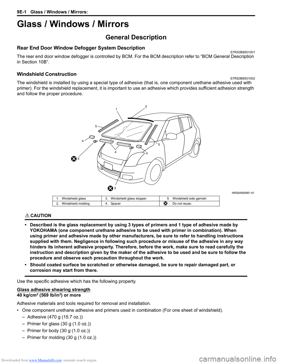
Windshield ConstructionS7RS0B9501002
The windshield is installed by using a special type of adhesive (that is, one component urethane adhesive used with
primer). For the windshield replacement, it is important to use an adhesive which provides sufficient adhesion strength
and follow the proper procedure.
CAUTION!
• Described is the glass replacement by using 3 types of primers and 1 type of adhesive made by YOKOHAMA (one component urethane adhesive to be used with primer in combination). When
using primer and adhesive made by other manufacturers, be sure to refer to handling instructions
supplied with them. Negligence in following such procedure or misuse of the adhesive in any way
hinders its inherent adhesive property. Therefore, before the work, make sure to read carefully the
instruction and description given by the maker of the adhesive to be used and be sure to follow the
procedure and observe each precaution throughout the work.
• Should coated surface be scratched or otherwise damaged, be sure to repair damaged part, or corrosion may start from there.
Use the specific adhesive which has the following property.
Glass adhesive shearing strength
40 kg/cm2 (569 lb/in2) or more
Adhesive materials and tools required for removal and installation.
• One component urethane adhesive and primers used in combination (For one sheet of windshield). – Adhesive (470 g (15.7 oz.))
– Primer for glass (30 g (1.0 oz.))
– Primer for body (30 g (1.0 oz.))
– Primer for molding (30 g (1.0 oz.))
3
3 1
2
44
4
5
5
I4RS0A950001-01
1. Windshield glass
3. Windshield glass stopper 5. Windshield side garnish
2. Windshield molding 4. Spacer : Do not reuse.
Page 1329 of 1496
Downloaded from www.Manualslib.com manuals search engine Glass / Windows / Mirrors: 9E-2
• Eyeleteer
• Piano string
• Windshield knife
• Brush for primer application (2 pcs)
•Knife
• Rubber sucker grip
• Sealant gun (for filling adhesive)
• Putty spatula (for correcting adhered parts)
Diagnostic Information and Procedures
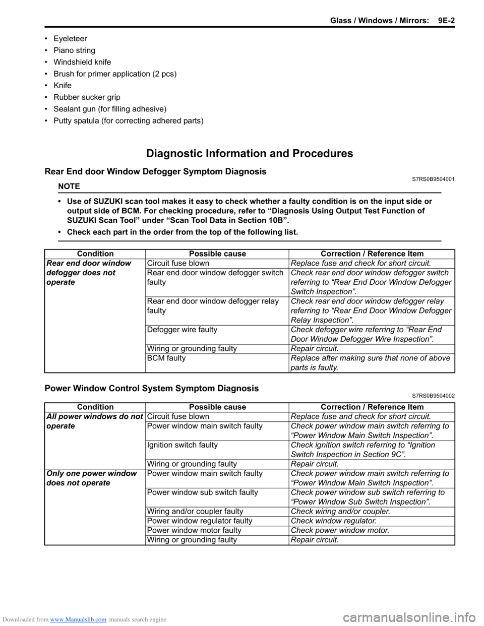
Rear End door Window Defogger Symptom DiagnosisS7RS0B9504001
NOTE
• Use of SUZUKI scan tool makes it easy to check whether a faulty condition is on the input side or
output side of BCM. For checking procedure, re fer to “Diagnosis Using Output Test Function of
SUZUKI Scan Tool” under “Scan Tool Data in Section 10B”.
• Check each part in the order from the top of the following list.
Power Window Control System Symptom DiagnosisS7RS0B9504002
Condition Possible cause Correction / Reference Item
Rear end door window
defogger does not
operate Circuit fuse blown
Replace fuse and check for short circuit.
Rear end door window defogger switch
faulty Check rear end door window defogger switch
referring to “Rear End Door Window Defogger
Switch Inspection”.
Rear end door window defogger relay
faulty Check rear end door window defogger relay
referring to “Rear End Door Window Defogger
Relay Inspection”.
Defogger wire faulty Check defogger wire referring to “Rear End
Door Window Defogger Wire Inspection”.
Wiring or grounding faulty Repair circuit.
BCM faulty Replace after making sure that none of above
parts is faulty.
ConditionPossible cause Correction / Reference Item
All power windows do not
operate Circuit fuse blown
Replace fuse and check for short circuit.
Power window main switch faulty Check power window main switch referring to
“Power Window Main Switch Inspection”.
Ignition switch faulty Check ignition switch referring to “Ignition
Switch Inspection in Section 9C”.
Wiring or grounding faulty Repair circuit.
Only one power window
does not operate Power window main switch faulty
Check power window main switch referring to
“Power Window Main Switch Inspection”.
Power window sub switch faulty Check power window sub switch referring to
“Power Window Sub Switch Inspection”.
Wiring and/or coupler faulty Check wiring and/or coupler.
Power window regulator faulty Check window regulator.
Power window motor faulty Check power window motor.
Wiring or grounding faulty Repair circuit.
Page 1331 of 1496
Downloaded from www.Manualslib.com manuals search engine Glass / Windows / Mirrors: 9E-4
Repair Instructions
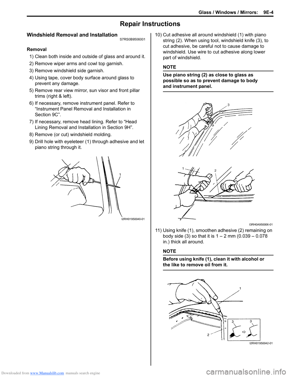
Windshield Removal and InstallationS7RS0B9506001
Removal1) Clean both inside and outside of glass and around it.
2) Remove wiper arms and cowl top garnish.
3) Remove windshield side garnish.
4) Using tape, cover body surface around glass to prevent any damage.
5) Remove rear view mirror , sun visor and front pillar
trims (right & left).
6) If necessary, remove instrument panel. Refer to “Instrument Panel Removal and Installation in
Section 9C”.
7) If necessary, remove he ad lining. Refer to “Head
Lining Removal and Installation in Section 9H”.
8) Remove (or cut) windshield molding.
9) Drill hole with eyeleteer (1 ) through adhesive and let
piano string through it. 10) Cut adhesive all around windshield (1) with piano
string (2). When using tool, windshield knife (3), to
cut adhesive, be careful not to cause damage to
windshield. Use wire to cut adhesive along lower
part of windshield.
NOTE
Use piano string (2) as close to glass as
possible so as to prevent damage to body
and instrument panel.
11) Using knife (1), smoothen adhesive (2) remaining on body side (3) so that it is 1 – 2 mm (0.039 – 0.078
in.) thick all around.
NOTE
Before using knife (1), clean it with alcohol or
the like to remove oil from it.
I2RH01950040-01
I3RH0A950006-01
I2RH01950042-01
Page 1332 of 1496
Downloaded from www.Manualslib.com manuals search engine 9E-5 Glass / Windows / Mirrors:
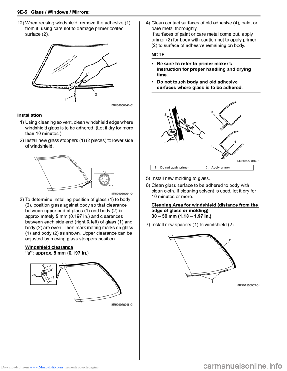
12) When reusing windshield, remove the adhesive (1) from it, using care not to damage primer coated
surface (2).
Installation 1) Using cleaning solvent, clean windshield edge where windshield glass is to be adhered. (Let it dry for more
than 10 minutes.)
2) Install new glass stoppers (1) (2 pieces) to lower side of windshield.
3) To determine installing position of glass (1) to body (2), position glass against body so that clearance
between upper end of glass (1) and body (2) is
approximately 5 mm (0.197 in.) and clearances
between each side end (right & left) of glass (1) and
body (2) are even. Then mark mating marks on glass
(1) and body (2) as shown. Upper clearance can be
adjusted by moving glass stoppers position.
Windshield clearance
“a”: approx. 5 mm (0.197 in.) 4) Clean contact surfaces of old adhesive (4), paint or
bare metal thoroughly.
If surfaces of paint or ba re metal come out, apply
primer (2) for body with caution not to apply primer
(2) to surface of adhesive remaining on body.
NOTE
• Be sure to refer to primer maker’s instruction for proper handling and drying
time.
• Do not touch body and old adhesive surfaces where glass is to be adhered.
5) Install new molding to glass.
6) Clean glass surface to be adhered to body with clean cloth. If cleaning solvent is used, let it dry for
10 minutes or more.
Cleaning Area for windshie ld (distance from the
edge of glass or molding)
30 – 50 mm (1.18 – 1.97 in.)
7) Install new spacers (1) to windshield (2).
I2RH01950043-01
1
I4RH01950001-01
2
1“a”
I2RH01950045-01
1. Do not apply primer 3. Apply primer
I2RH01950046-01
2
1I4RS0A950002-01
Page 1333 of 1496
Downloaded from www.Manualslib.com manuals search engine Glass / Windows / Mirrors: 9E-6
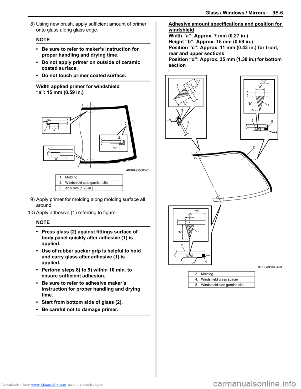
8) Using new brush, apply sufficient amount of primer onto glass along glass edge.
NOTE
• Be sure to refer to maker’s instruction for
proper handling and drying time.
• Do not apply primer on outside of ceramic coated surface.
• Do not touch primer coated surface.
Width applied primer for windshield
“a”: 15 mm (0.59 in.)
9) Apply primer for molding along molding surface all around.
10) Apply adhesive (1) referring to figure.
NOTE
• Press glass (2) against fittings surface of body panel quickly after adhesive (1) is
applied.
• Use of rubber sucker gr ip is helpful to hold
and carry glass after adhesive (1) is
applied.
• Perform steps 8) to 9) within 10 min. to ensure sufficient adhesion.
• Be sure to refer to adhesive maker’s instruction for proper handling and drying
time.
• Start from bottom side of glass (2).
• Be careful not to damage primer.
Adhesive amount specifications and position for
windshield
Width “a”: Approx. 7 mm (0.27 in.)
Height “b”: Approx. 15 mm (0.59 in.)
Position “c”: Approx. 11 mm (0.43 in.) for front,
rear and upper sections
Position “d”: Approx. 35 mm (1.38 in.) for bottom
section
1. Molding
2. Windshield side garnish clip
3. 32.5 mm (1.28 in.)
“a”
1
“a”
“a”
2
3
I4RS0A950003-01
3. Molding
4. Windshield glass spacer
5. Windshield side garnish clip
2
2
4
1
“b” “d”
“b”
“c”
2
1
“a”
3
2
1
“b”
“c”
5
“a”
“a”
I4RS0A950004-01
Page 1334 of 1496
Downloaded from www.Manualslib.com manuals search engine 9E-7 Glass / Windows / Mirrors:
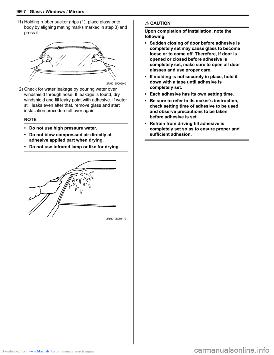
11) Holding rubber sucker grips (1), place glass onto body by aligning mating marks marked in step 3) and
press it.
12) Check for water leakage by pouring water over windshield through hose. If leakage is found, dry
windshield and fill leaky po int with adhesive. If water
still leaks even after that , remove glass and start
installation procedure all over again.
NOTE
• Do not use high pressure water.
• Do not blow compressed air directly at adhesive applied part when drying.
• Do not use infrared lamp or like for drying.
CAUTION!
Upon completion of installation, note the
following.
• Sudden closing of door before adhesive is completely set may cause glass to become
loose or to come off. Therefore, if door is
opened or closed before adhesive is
completely set, make sure to open all door
glasses and use proper care.
• If molding is not securely in place, hold it down with a tape until adhesive is
completely set.
• Each adhesive has its own setting time.
• Be sure to refer to its maker’s instruction, check setting time of adhesive to be used
and observe precautions to be taken
before adhesive is set.
• Refrain from driving till adhesive is completely set so as to ensure proper and
sufficient adhesion.
I2RH01950050-01
I2RH01950051-01