9a 102 SUZUKI SWIFT 2007 2.G Service Repair Manual
[x] Cancel search | Manufacturer: SUZUKI, Model Year: 2007, Model line: SWIFT, Model: SUZUKI SWIFT 2007 2.GPages: 1496, PDF Size: 34.44 MB
Page 656 of 1496
Downloaded from www.Manualslib.com manuals search engine 5A-12 Automatic Transmission/Transaxle:
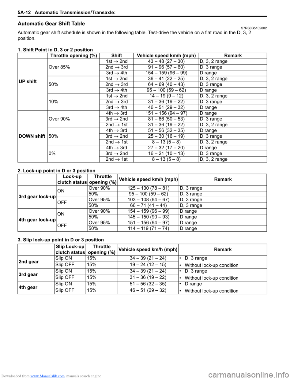
Automatic Gear Shift TableS7RS0B5102002
Automatic gear shift schedule is shown in the following table. Test-drive the vehicle on a flat road in the D, 3, 2
position.
1. Shift Point in D, 3 or 2 position
2. Lock-up point in D or 3 position
3. Slip lock-up point in D or 3 position Throttle opening (%) Shift Vehicle speed km/h (mph) Remark
UP shift Over 85%
1st →
2nd 43 – 48 (27 – 30) D, 3, 2 range
2nd → 3rd 91 – 96 (57 – 60) D, 3 range
3rd → 4th 154 – 159 (96 – 99) D range
50% 1st →
2nd 36 – 41 (22 – 25) D, 3, 2 range
2nd → 3rd 64 – 69 (40 – 43) D, 3 range
3rd → 4th 95 – 100 (59 – 62) D range
10% 1st →
2nd 14 – 19 (9 – 12) D, 3, 2 range
2nd → 3rd 31 – 36 (19 – 22) D, 3 range
3rd → 4th 46 – 51 (29 – 32) D range
DOWN shift Over 90%
4th
→ 3rd 151 – 156 (94 – 97) D range
3rd → 2nd 81 – 86 (50 – 53) D, 3 range
2nd → 1st 31 – 36 (19 – 22) D, 3, 2 range
50% 4th
→ 3rd 51 – 56 (32 – 35) D range
3rd → 2nd 25 – 30 (16 – 19) D, 3 range
2nd → 1st 8 – 13 (5 – 8) D, 3, 2 range
0% 4th
→ 3rd 27 – 32 (17 – 20) D range
3rd → 2nd 16 – 21 (10 – 13) D, 3 range
2nd → 1st 8 – 13 (5 – 8) D, 3, 2 range
Lock-up
clutch status Throttle
opening (%) Vehicle speed km/h (mph) Remark
3rd gear lock-up ON
Over 90% 125 – 130 (78 – 81) D, 3 range
50% 95 – 100 (59 – 62) D, 3 range
OFF Over 95% 103 – 108 (64 – 67) D, 3 range
50% 66 – 71 (41 – 44) D, 3 range
4th gear lock-up ON
Over 90% 154 – 159 (96 – 99) D range
50% 145 – 150 (90 – 93) D range
OFF Over 95% 151 – 156 (94 – 97) D range
50% 114 – 119 (71 – 74) D range
Slip Lock-up
clutch status Throttle
opening (%) Vehicle speed km/h (mph) Remark
2nd gear Slip ON 15% 34 – 39 (21 – 24) • D, 3 range
• Without lock-up condition
Slip OFF 15% 19 – 24 (12 – 15)
3rd gear Slip ON 15% 34 – 39 (21 – 24) • D, 3 range
• Without lock-up condition
Slip OFF 15% 31 – 36 (19 – 22)
4th gear Slip ON 15% 51 – 56 (32 – 35) • D range
• Without lock-up condition
Slip OFF 15% 46 – 51 (29 – 32)
Page 746 of 1496
Downloaded from www.Manualslib.com manuals search engine 5A-102 Automatic Transmission/Transaxle:
Operation Check
Check pressure control solenoid valves (Pressure
control solenoid and TCC pressure control solenoid)
operation in the either manner of the following.
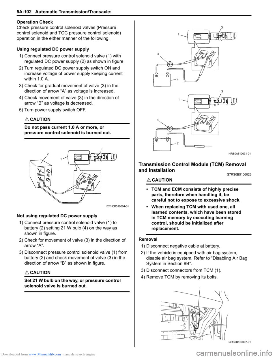
Using regulated DC power supply
1) Connect pressure contro l solenoid valve (1) with
regulated DC power supply (2) as shown in figure.
2) Turn regulated DC power supply switch ON and increase voltage of power supply keeping current
within 1.0 A.
3) Check for gradual movement of valve (3) in the direction of arrow “A” as voltage is increased.
4) Check movement of valve (3) in the direction of arrow “B” as voltage is decreased.
5) Turn power supply switch OFF.
CAUTION!
Do not pass current 1.0 A or more, or
pressure control solenoid is burned out.
Not using regulated DC power supply 1) Connect pressure control solenoid valve (1) to battery (2) setting 21 W bulb (4) on the way as
shown in figure.
2) Check for movement of valve (3) in the direction of arrow “A”.
3) Disconnect pressure control solenoid valve (1) from battery (2) and check movement of valve (3) in the
direction of arrow “B” as shown in figure.
CAUTION!
Set 21 W bulb on the way, or pressure control
solenoid valve is burned out.
Transmission Control Module (TCM) Removal
and Installation
S7RS0B5106026
CAUTION!
• TCM and ECM consists of highly precise
parts, therefore when handling it, be
careful not to expose to excessive shock.
• When replacing TCM with used one, all learned contents, which have been stored
in TCM memory by executing learning
control, should be initialized after
replacement.
Removal
1) Disconnect negative cable at battery.
2) If the vehicle is equipped with air bag system, disable air bag system. Refer to “Disabling Air Bag
System in Section 8B”.
3) Disconnect connectors from TCM (1).
4) Remove TCM by removing its bolts.
I2RH0B510064-01
I4RS0A510031-01
1
I4RS0B510007-01
Page 758 of 1496
Downloaded from www.Manualslib.com manuals search engine 5A-114 Automatic Transmission/Transaxle:
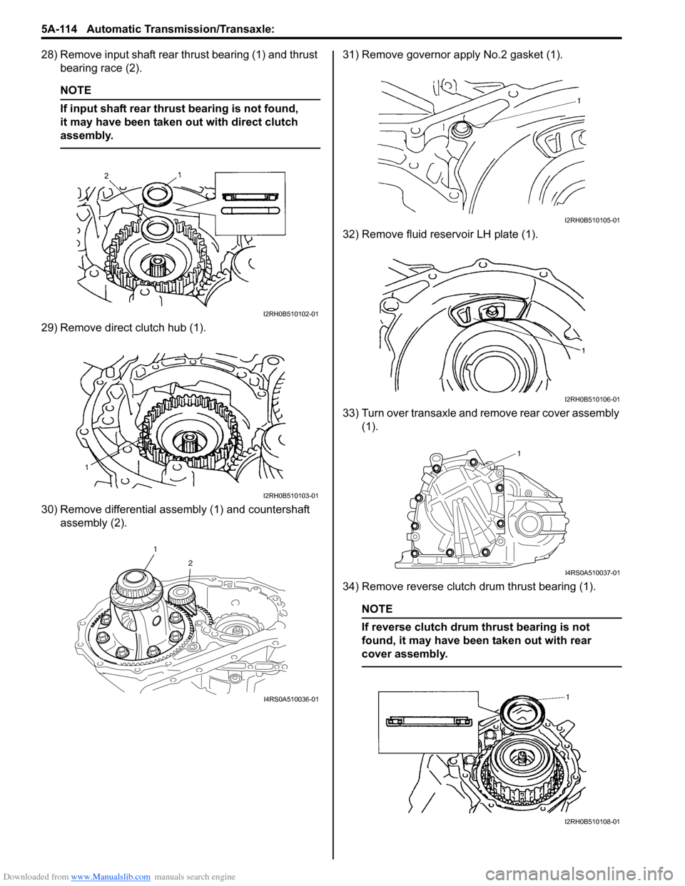
28) Remove input shaft rear thrust bearing (1) and thrust bearing race (2).
NOTE
If input shaft rear thrust bearing is not found,
it may have been taken out with direct clutch
assembly.
29) Remove direct clutch hub (1).
30) Remove differential assembly (1) and countershaft assembly (2). 31) Remove governor apply No.2 gasket (1).
32) Remove fluid reservoir LH plate (1).
33) Turn over transaxle and remove rear cover assembly
(1).
34) Remove reverse clutch drum thrust bearing (1).
NOTE
If reverse clutch drum thrust bearing is not
found, it may have been taken out with rear
cover assembly.
I2RH0B510102-01
I2RH0B510103-01
1 2
I4RS0A510036-01
I2RH0B510105-01
I2RH0B510106-01
1
I4RS0A510037-01
I2RH0B510108-01
Page 779 of 1496
Downloaded from www.Manualslib.com manuals search engine Automatic Transmission/Transaxle: 5A-135
Reassembly
Reverse disassembly procedure for assembly, noting the
following points.
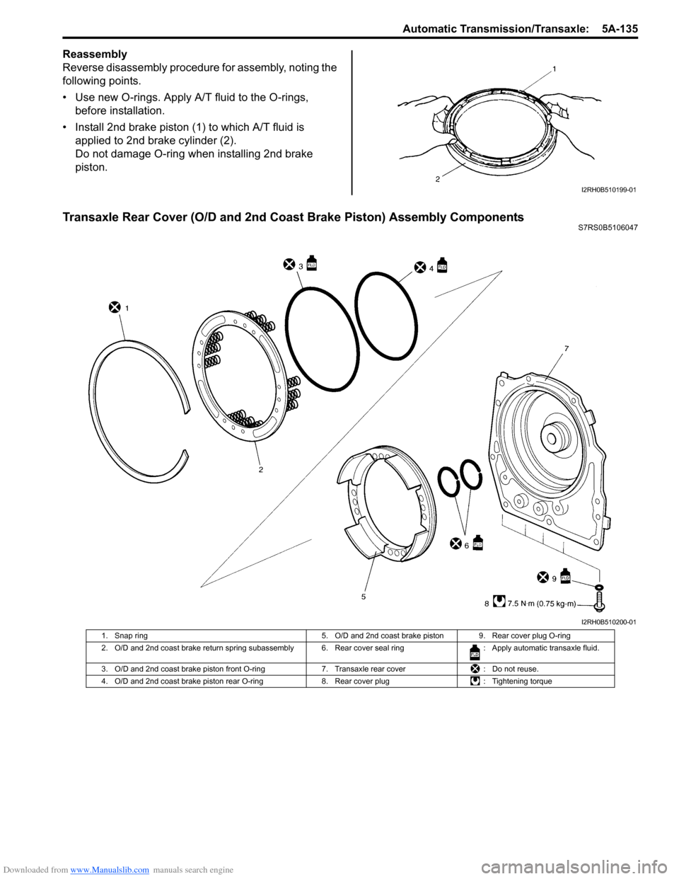
• Use new O-rings. Apply A/T fluid to the O-rings, before installation.
• Install 2nd brake piston (1) to which A/T fluid is applied to 2nd brake cylinder (2).
Do not damage O-ring wh en installing 2nd brake
piston.
Transaxle Rear Cover (O/D and 2nd Coast Brake Piston) Assembly ComponentsS7RS0B5106047
I2RH0B510199-01
I2RH0B510200-01
1. Snap ring 5. O/D and 2nd coast brake piston 9. Rear cover plug O-ring
2. O/D and 2nd coast brake return spring subassembly 6. R ear cover seal ring: Apply automatic transaxle fluid.
3. O/D and 2nd coast brake piston front O- ring7. Transaxle rear cover : Do not reuse.
4. O/D and 2nd coast brake piston rear O- ring8. Rear cover plug : Tightening torque
Page 780 of 1496
Downloaded from www.Manualslib.com manuals search engine 5A-136 Automatic Transmission/Transaxle:
Transaxle Rear Cover (O/D and 2nd Coast Brake
Piston) Assembly Disassembly and
Reassembly
S7RS0B5106048
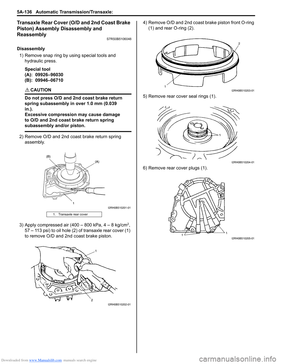
Disassembly1) Remove snap ring by using special tools and hydraulic press.
Special tool
(A): 09926–96030
(B): 09946–06710
CAUTION!
Do not press O/D and 2nd coast brake return
spring subassembly in over 1.0 mm (0.039
in.).
Excessive compression may cause damage
to O/D and 2nd coast brake return spring
subassembly and/or piston.
2) Remove O/D and 2nd coast brake return spring assembly.
3) Apply compressed air (400 – 800 kPa, 4 – 8 kg/cm
2,
57 – 113 psi) to oil hole (2) of transaxle rear cover (1)
to remove O/D and 2nd coast brake piston. 4) Remove O/D and 2nd coast brake piston front O-ring
(1) and rear O-ring (2).
5) Remove rear cove r seal rings (1).
6) Remove rear cover plugs (1).
1. Transaxle rear cover
I2RH0B510201-01
I2RH0B510202-01
I2RH0B510203-01
I2RH0B510204-01
I2RH0B510205-01
Page 781 of 1496
Downloaded from www.Manualslib.com manuals search engine Automatic Transmission/Transaxle: 5A-137
Reassembly
Reverse disassembly procedure for assembly, noting the
following points.
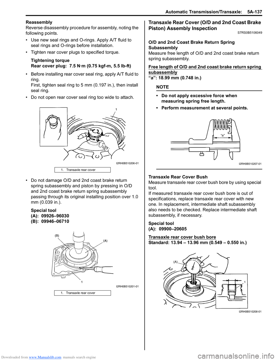
• Use new seal rings and O-rings. Apply A/T fluid to seal rings and O-rings before installation.
• Tighten rear cover plugs to specified torque.
Tightening torque
Rear cover plug: 7.5 N·m (0.75 kgf-m, 5.5 lb-ft)
• Before installing rear cover seal ring, apply A/T fluid to ring.
First, tighten seal ring to 5 mm (0.197 in.), then install
seal ring.
• Do not open rear cover seal ring too wide to attach.
• Do not damage O/D and 2nd coast brake return spring subassembly and piston by pressing in O/D
and 2nd coast brake return spring subassembly
passing through its original installing position over 1.0
mm (0.039 in.).
Special tool
(A): 09926–96030
(B): 09946–06710Transaxle Rear Cover (O/D and 2nd Coast Brake
Piston) Assembly Inspection
S7RS0B5106049
O/D and 2nd Coast Brake Return Spring
Subassembly
Measure free length of O/D and 2nd coast brake return
spring subassembly.
Free length of O/D and 2nd coast brake return spring
subassembly
“a”: 18.99 mm (0.748 in.)
NOTE
• Do not apply excessive force when measuring spring free length.
• Perform measurement at several points.
Transaxle Rear Cover Bush
Measure transaxle rear cover bush bore by using special
tool.
If measured transaxle rear cover bush bore is out of
specifications, replace transaxle rear cover with new
one. In replacement, inte rmediate shaft subassembly
also needs to be checked. Replace intermediate shaft
subassembly, if necessary.
Special tool
(A): 09900–20605
Transaxle rear cover bush bore
Standard: 13.94 – 13.96 mm (0.549 – 0.550 in.)
1. Transaxle rear cover
1. Transaxle rear cover
I2RH0B510206-01
I2RH0B510201-01
I2RH0B510207-01
I2RH0B510208-01
Page 782 of 1496
Downloaded from www.Manualslib.com manuals search engine 5A-138 Automatic Transmission/Transaxle:
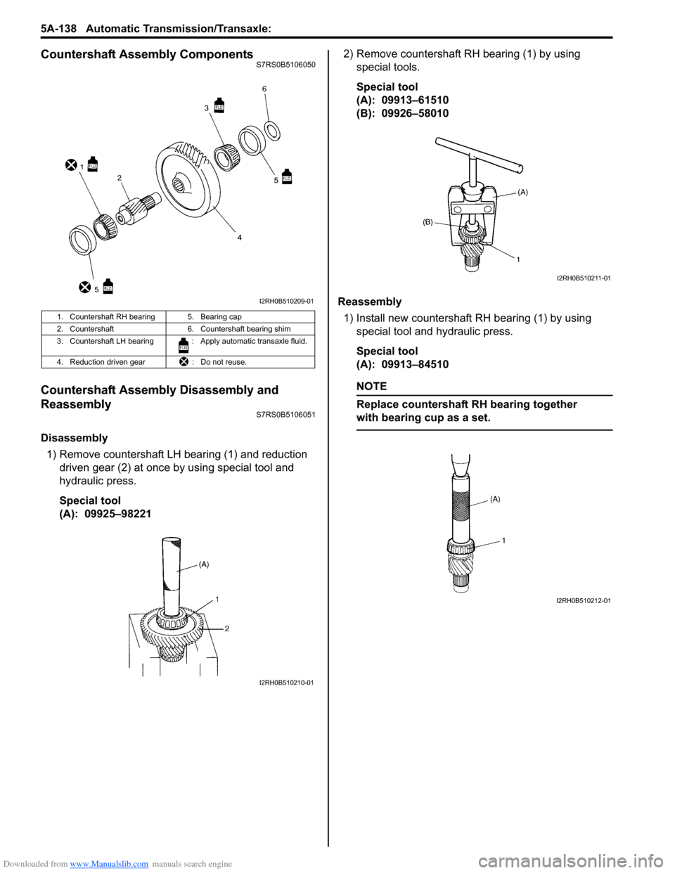
Countershaft Assembly ComponentsS7RS0B5106050
Countershaft Assembly Disassembly and
Reassembly
S7RS0B5106051
Disassembly1) Remove countershaft LH bearing (1) and reduction driven gear (2) at once by using special tool and
hydraulic press.
Special tool
(A): 09925–98221 2) Remove countershaft RH bearing (1) by using
special tools.
Special tool
(A): 09913–61510
(B): 09926–58010
Reassembly 1) Install new countershaft RH bearing (1) by using special tool and hydraulic press.
Special tool
(A): 09913–84510
NOTE
Replace countershaft RH bearing together
with bearing cup as a set.
1. Countershaft RH bearing 5. Bearing cap
2. Countershaft 6. Countershaft bearing shim
3. Countershaft LH bearing : Apply automatic transaxle fluid.
4. Reduction driven gear : Do not reuse.
I2RH0B510209-01
I2RH0B510210-01
I2RH0B510211-01
I2RH0B510212-01
Page 783 of 1496
Downloaded from www.Manualslib.com manuals search engine Automatic Transmission/Transaxle: 5A-139
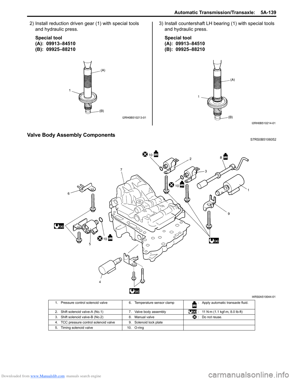
2) Install reduction driven gear (1) with special tools and hydraulic press.
Special tool
(A): 09913–84510
(B): 09925–88210 3) Install countershaft LH bearing (1) with special tools
and hydraulic press.
Special tool
(A): 09913–84510
(B): 09925–88210
Valve Body Assembly ComponentsS7RS0B5106052
I2RH0B510213-01
I2RH0B510214-01
I4RS0A510044-01
1. Pressure control solenoid valve 6. Temperature sensor clamp : Apply automatic transaxle fluid.
2. Shift solenoid valve-A (No.1) 7. Valve body assembly: 11 N⋅m (1.1 kgf-m, 8.0 lb-ft)
3. Shift solenoid valve-B (No.2) 8. Manual valve: Do not reuse.
4. TCC pressure control solenoid valve 9. Solenoid lock plate
5. Timing solenoid valve 10. O-ring
Page 784 of 1496
Downloaded from www.Manualslib.com manuals search engine 5A-140 Automatic Transmission/Transaxle:
Valve Body Assembly Disassembly and
Reassembly
S7RS0B5106053
CAUTION!
When replacing pressure control solenoid
valve and/or TCC pressure control solenoid
valve, it is strictly required to replace it
together with valve body assembly as a set.
Replacing pressure control solenoid valve
and/or TCC pressure control solenoid valve
independently may cause excessive shift
shock.
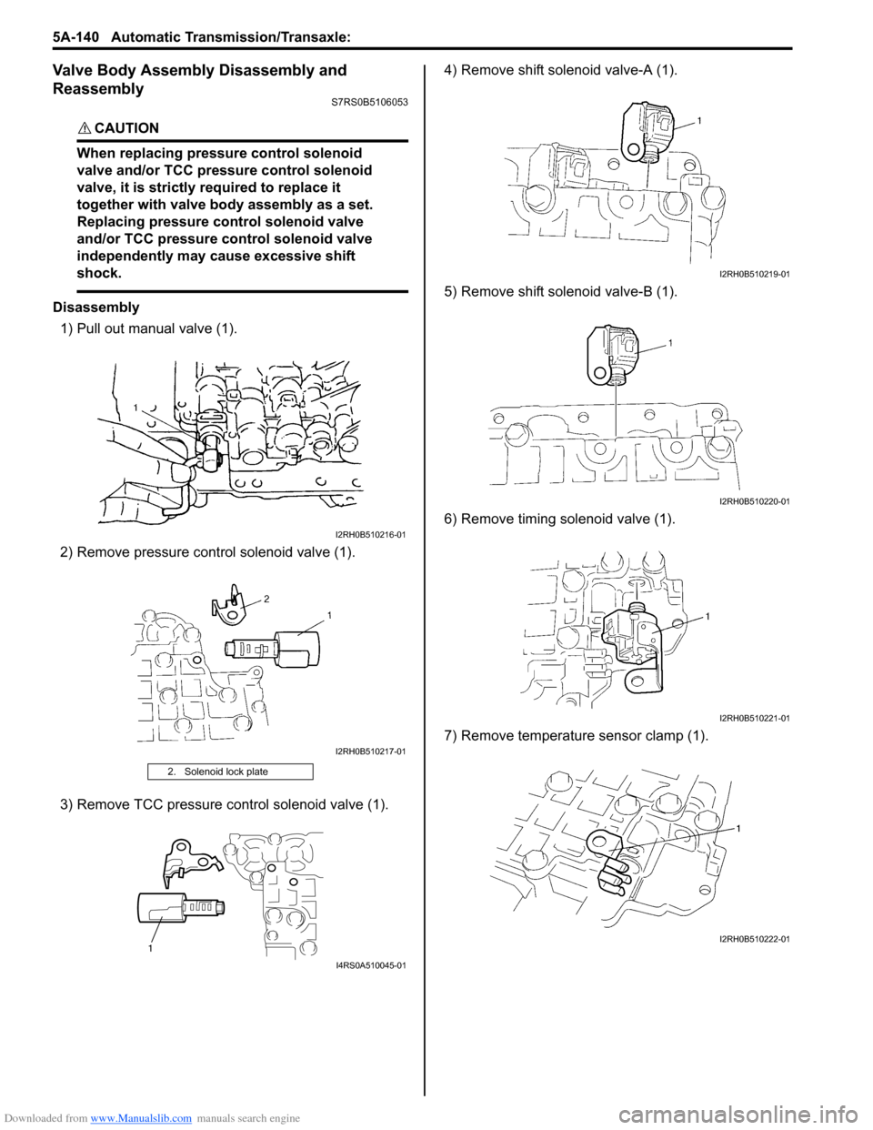
Disassembly1) Pull out manual valve (1).
2) Remove pressure cont rol solenoid valve (1).
3) Remove TCC pressure control solenoid valve (1). 4) Remove shift solenoid valve-A (1).
5) Remove shift solenoid valve-B (1).
6) Remove timing solenoid valve (1).
7) Remove temperature sensor clamp (1).
2. Solenoid lock plate
I2RH0B510216-01
I2RH0B510217-01
1
I4RS0A510045-01
I2RH0B510219-01
I2RH0B510220-01
I2RH0B510221-01
I2RH0B510222-01
Page 785 of 1496
Downloaded from www.Manualslib.com manuals search engine Automatic Transmission/Transaxle: 5A-141
Reassembly
Reverse disassembly procedure for assembly, noting the
following points.
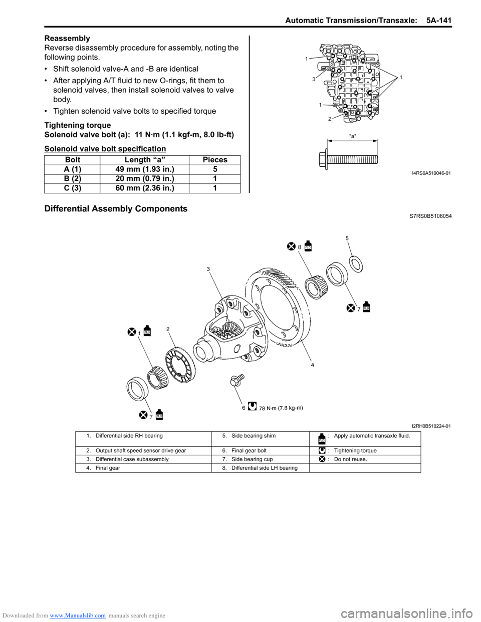
• Shift solenoid valve-A and -B are identical
• After applying A/T fluid to new O-rings, fit them to solenoid valves, then insta ll solenoid valves to valve
body.
• Tighten solenoid valve bolts to specified torque
Tightening torque
Solenoid valve bolt (a): 11 N·m (1.1 kgf-m, 8.0 lb-ft)
Solenoid valve bolt specification
Differential Assembly ComponentsS7RS0B5106054
Bolt Length “a” Pieces
A (1) 49 mm (1.93 in.) 5
B (2) 20 mm (0.79 in.) 1
C (3) 60 mm (2.36 in.) 1
1
1
1
3
2
"a"
I4RS0A510046-01
I2RH0B510224-01
1. Differential side RH bearing 5. Side bearing shim: Apply automatic transaxle fluid.
2. Output shaft speed sensor drive gear 6. Final gear bolt: Tightening torque
3. Differential case subassembly 7. Side bearing cup: Do not reuse.
4. Final gear 8. Differential side LH bearing