cat SUZUKI SWIFT 2007 2.G Service Repair Manual
[x] Cancel search | Manufacturer: SUZUKI, Model Year: 2007, Model line: SWIFT, Model: SUZUKI SWIFT 2007 2.GPages: 1496, PDF Size: 34.44 MB
Page 85 of 1496
Downloaded from www.Manualslib.com manuals search engine Engine General Information and Diagnosis: 1A-35
Scan Tool Data Definitions
COOLANT TEMP (ENGINE COOLANT
TEMPERATURE, °C, °F)
It is detected by engine coolant temp. sensor.
INTAKE AIR TEMP. ( °C, °F)
It is detected by intake air temp. sensor.
ENGINE SPEED (rpm)
It is computed by reference pulses from the camshaft
position sensor.
INJ PULSE WIDTH (FUEL INJECTION PULSE WIDTH,
msec.)
This parameter indicates time of the injector drive (valve
opening) pulse which is output from ECM (but injector
drive time of NO.1 cylinder fo r multiport fuel injection).
DESIRED IDLE (DESIRED IDLE SPEED, rpm)
The Desired Idle Speed is an ECM internal parameter
which indicates the ECM requested idle. If the engine is
not running, this number is not valid.
SHORT FT B1 (SHORT TERM FUEL TRIM, %)
Short term fuel trim valu e represents short term
corrections to the air/fuel mixture computation. A value
of 0 indicates no correction, a value greater than 0
means an enrichment correction, and a value less than 0
implies an enleanment correction. LONG FT B1 (LONG TERM FUEL TRIM, %)
Long term fuel trim value represents long term
corrections to the air/fuel mixture computation. A value
of 0 indicates no correction, a value greater than 0
means an enrichment correction, and a value less than 0
implies an enleanment correction.
TOTAL FUEL TRIM B1 (%)
The value of Total Fuel Trim is obtained by calculating
based on values of Short Term Fuel Trim and Long Term
Fuel Trim. This value indica
tes how much correction is
necessary to keep the air/fuel mixture stoichiometrical.
MAF (MASS AIR FLOW RATE, g/s, lb/min.)
It represents total mass of air entering intake manifold
which is measured by mass air flow sensor.
CALC LOAD (CALCULATED LOAD VALUE, %)
Engine load displayed as a percentage of maximum
possible load. Value is calculated mathematically using
the formula: actual (current) intake air volume ÷
maximum possible intake air volume × 100%
THROTTLE POS (ABSOLUTE THROTTLE POSITION,
%)
When throttle position sensor is at fully closed position,
throttle opening is indicated as 0 – 5% and 90 – 100%
full open position.
O2S SENSOR B1 S1 (HEA TED OXYGEN SENSOR-1,
V)
It indicates output voltage of HO2S-1 installed on
exhaust manifold (pre-catalyst).
)
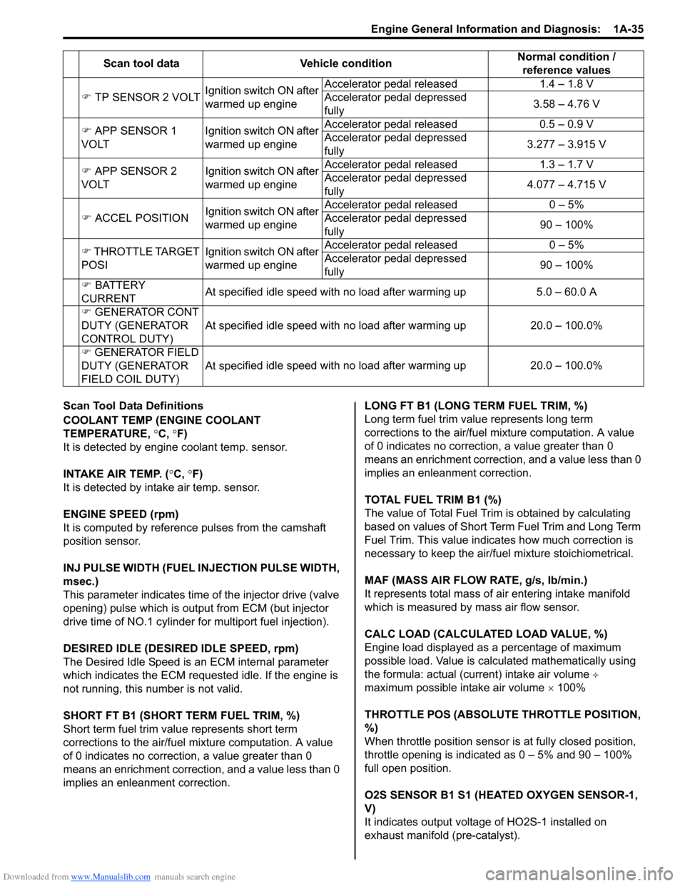
TP SENSOR 2 VOLT Ignition switch ON after
warmed up engine Accelerator pedal released
1.4 – 1.8 V
Accelerator pedal depressed
fully 3.58 – 4.76 V
) APP SENSOR 1
VOLT Ignition switch ON after
warmed up engineAccelerator pedal released
0.5 – 0.9 V
Accelerator pedal depressed
fully 3.277 – 3.915 V
) APP SENSOR 2
VOLT Ignition switch ON after
warmed up engineAccelerator pedal released
1.3 – 1.7 V
Accelerator pedal depressed
fully 4.077 – 4.715 V
) ACCEL POSITION Ignition switch ON after
warmed up engine Accelerator pedal released
0 – 5%
Accelerator pedal depressed
fully 90 – 100%
) THROTTLE TARGET
POSI Ignition switch ON after
warmed up engineAccelerator pedal released
0 – 5%
Accelerator pedal depressed
fully 90 – 100%
) BATTERY
CURRENT At specified idle speed with no load after warming up
5.0 – 60.0 A
) GENERATOR CONT
DUTY (GENERATOR
CONTROL DUTY) At specified idle speed with no load after warming up
20.0 – 100.0%
) GENERATOR FIELD
DUTY (GENERATOR
FIELD COIL DUTY) At spe
cified idle speed with no load after warming up
20.0 – 100.0%
Scan tool data
Vehicle condition Normal condition /
reference values
Page 86 of 1496
Downloaded from www.Manualslib.com manuals search engine 1A-36 Engine General Information and Diagnosis:
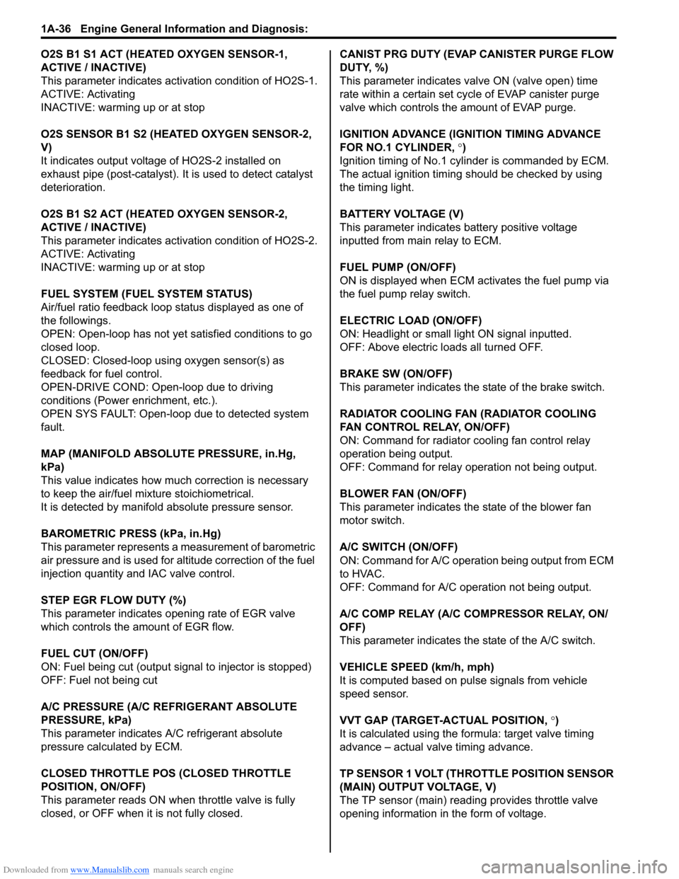
O2S B1 S1 ACT (HEATED OXYGEN SENSOR-1,
ACTIVE / INACTIVE)
This parameter indicates activation condition of HO2S-1.
ACTIVE: Activating
INACTIVE: warming up or at stop
O2S SENSOR B1 S2 (HEATED OXYGEN SENSOR-2,
V)
It indicates output voltage of HO2S-2 installed on
exhaust pipe (post-catalyst). It is used to detect catalyst
deterioration.
O2S B1 S2 ACT (HEATED OXYGEN SENSOR-2,
ACTIVE / INACTIVE)
This parameter indicates acti vation condition of HO2S-2.
ACTIVE: Activating
INACTIVE: warming up or at stop
FUEL SYSTEM (FUEL SYSTEM STATUS)
Air/fuel ratio feedback loop status displayed as one of
the followings.
OPEN: Open-loop has not yet satisfied conditions to go
closed loop.
CLOSED: Closed-loop using oxygen sensor(s) as
feedback for fuel control.
OPEN-DRIVE COND: Open-loop due to driving
conditions (Power enrichment, etc.).
OPEN SYS FAULT: Open-loop due to detected system
fault.
MAP (MANIFOLD ABSOLUTE PRESSURE, in.Hg,
kPa)
This value indicates how much correction is necessary
to keep the air/fuel mixture stoichiometrical.
It is detected by manifold absolute pressure sensor.
BAROMETRIC PRESS (kPa, in.Hg)
This parameter represents a measurement of barometric
air pressure and is used for al titude correction of the fuel
injection quantity and IAC valve control.
STEP EGR FLOW DUTY (%)
This parameter indicates opening rate of EGR valve
which controls the amount of EGR flow.
FUEL CUT (ON/OFF)
ON: Fuel being cut (output signal to injector is stopped)
OFF: Fuel not being cut
A/C PRESSURE (A/C REFRIGERANT ABSOLUTE
PRESSURE, kPa)
This parameter indicates A/C refrigerant absolute
pressure calculated by ECM.
CLOSED THROTTLE PO S (CLOSED THROTTLE
POSITION, ON/OFF)
This parameter reads ON wh en throttle valve is fully
closed, or OFF when it is not fully closed. CANIST PRG DUTY (EVAP CANISTER PURGE FLOW
DUTY, %)
This parameter indicates valve ON (valve open) time
rate within a certain set cycle of EVAP canister purge
valve which controls the amount of EVAP purge.
IGNITION ADVANCE (IGNITION TIMING ADVANCE
FOR NO.1 CYLINDER,
°)
Ignition timing of No.1 cylinder is commanded by ECM.
The actual ignition timing should be checked by using
the timing light.
BATTERY VOLTAGE (V)
This parameter indicates battery positive voltage
inputted from main relay to ECM.
FUEL PUMP (ON/OFF)
ON is displayed when ECM activates the fuel pump via
the fuel pump relay switch.
ELECTRIC LOAD (ON/OFF)
ON: Headlight or small light ON signal inputted.
OFF: Above electric loads all turned OFF.
BRAKE SW (ON/OFF)
This parameter indicates the state of the brake switch.
RADIATOR COOLING FAN (RADIATOR COOLING
FAN CONTROL RELAY, ON/OFF)
ON: Command for radiator cooling fan control relay
operation being output.
OFF: Command for relay operation not being output.
BLOWER FAN (ON/OFF)
This parameter indicates the state of the blower fan
motor switch.
A/C SWITCH (ON/OFF)
ON: Command for A/C operatio n being output from ECM
to HVAC.
OFF: Command for A/C oper ation not being output.
A/C COMP RELAY (A/C COMPRESSOR RELAY, ON/
OFF)
This parameter indicates the state of the A/C switch.
VEHICLE SPEED (km/h, mph)
It is computed based on pulse signals from vehicle
speed sensor.
VVT GAP (TARGET-ACTUAL POSITION, °)
It is calculated using the formula: target valve timing
advance – actual valve timing advance.
TP SENSOR 1 VOLT (THROTTLE POSITION SENSOR
(MAIN) OUTPUT VOLTAGE, V)
The TP sensor (main) reading provides throttle valve
opening information in the form of voltage.
Page 87 of 1496
Downloaded from www.Manualslib.com manuals search engine Engine General Information and Diagnosis: 1A-37
TP SENSOR 2 VOLT (THROTTLE POSITION SENSOR
(SUB) OUTPUT VOLTAGE, V)
The TP sensor (sub) reading provides throttle valve
opening information in the form of voltage.
APP SENSOR 1 VOLT (ACCELERATOR PEDAL
POSITION (APP) SENSOR (MAIN) OUTPUT
VOLTAGE, V)
The APP sensor (main) read ing provides accelerator
pedal opening information in the form of voltage.
APP SENSOR 2 VOLT (ACCELERATOR PEDAL
POSITION (APP) SENSOR (S UB) OUTPUT VOLTAGE,
V)
The APP sensor (sub) reading provides accelerator
pedal opening information in the form of voltage.
ACCEL POSITION (ABSOLUTE ACCELERATOR
PEDAL POSITION, %)
When accelerator pedal is at fully released position,
accelerator pedal is indicated as 0 – 5% and 90 – 100%
fully depressed position. THROTTLE TARGET POSI (TARGET THROTTLE
VALVE POSITION, %)
Target throttle valve position is ECM internal parameter
which indicates the ECM requested throttle valve
position.
BATTERY CURRENT (A)
This parameter indicates elec
tric load value (current
consumption) that detected by electric load current
sensor.
GENERATOR CONT DUTY (GENERATOR CONTROL
DUTY, %)
This parameter indicates generator control duty ratio that
controls production electricity of generator by ECM.
100%: No limitation for the generating
0%: Maximum limitation for the generating
GENERATOR FIELD DUTY (GENERATOR FIELD
COIL DUTY, %)
This parameter indicates ope rating rate (status of
production electricity) for gen erator by field coil duty
ratio.
100%: maximum operation.
0%: minimum operation.
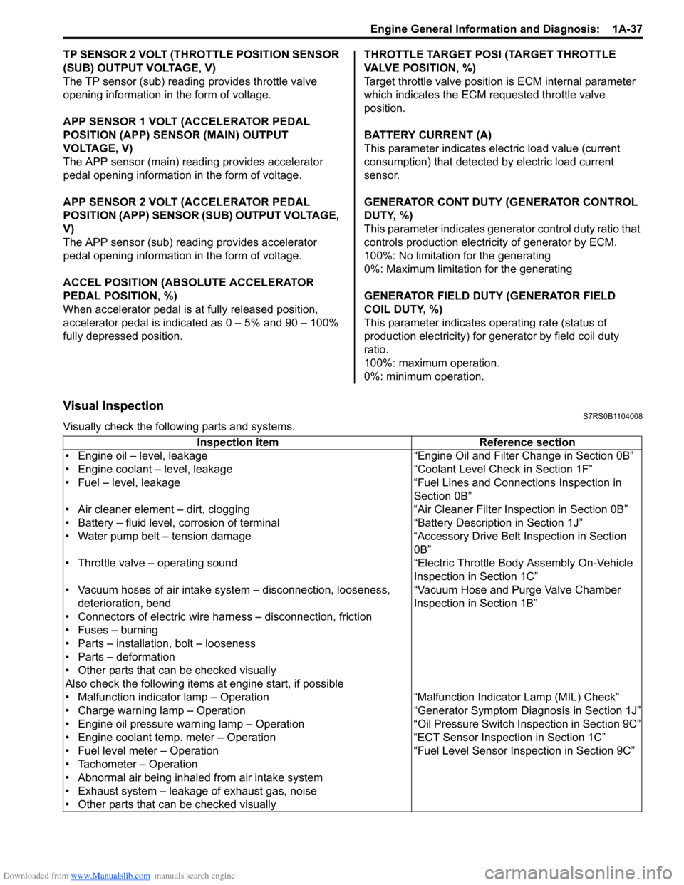
Visual InspectionS7RS0B1104008
Visually check the following parts and systems.
Inspection item Reference section
• Engine oil – level, leakage “Engine Oil and Filter Change in Section 0B”
• Engine coolant – level, leakage “Co olant Level Check in Section 1F”
• Fuel – level, leakage “Fuel Lines and Connections Inspection in Section 0B”
• Air cleaner element – dirt, clogging “Air Cleaner Filter Inspection in Section 0B”
• Battery – fluid level, corrosion of terminal “Battery Description in Section 1J”
• Water pump belt – tension damage “Accessory Drive Belt Inspection in Section 0B”
• Throttle valve – operating sound “Electric Throttle Body Assembly On-Vehicle Inspection in Section 1C”
• Vacuum hoses of air intake system – disconnection, looseness,
deterioration, bend “Vacuum Hose and Purge Valve Chamber
Inspection in Section 1B”
• Connectors of electric wire harness – disconnection, friction
• Fuses – burning
• Parts – installation, bolt – looseness
• Parts – deformation
• Other parts that can be checked visually
Also check the following items at engine start, if possible
• Malfunction indicator lamp – Operation “Malfunction Indicator Lamp (MIL) Check”
• Charge warning lamp – Operation “Genera tor Symptom Diagnosis in Section 1J”
• Engine oil pressure warning lamp – Operation “O il Pressure Switch Inspection in Section 9C”
• Engine coolant temp. meter – Operation “ECT Sensor Inspection in Section 1C”
• Fuel level meter – Operation “Fuel Level Sensor Inspection in Section 9C”
• Tachometer – Operation
• Abnormal air being inhaled from air intake system
• Exhaust system – leakage of exhaust gas, noise
• Other parts that can be checked visually
Page 93 of 1496
Downloaded from www.Manualslib.com manuals search engine Engine General Information and Diagnosis: 1A-43
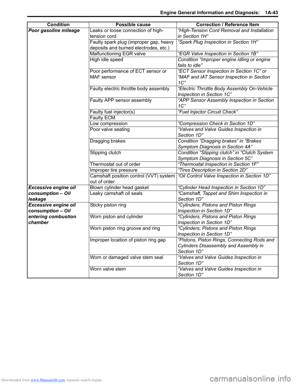
Poor gasoline mileageLeaks or loose connection of high-
tension cord “High-Tension Cord Removal and Installation
in Section 1H”
Faulty spark plug (improper gap, heavy
deposits and burned electrodes, etc.) “Spark Plug Inspection in Section 1H”
Malfunctioning EGR valve “EGR Valve Inspection in Section 1B”
High idle speed Condition “Improper engine idling or engine
fails to idle”
Poor performance of ECT sensor or
MAF sensor “ECT Sensor Inspection in Section 1C” or
“MAF and IAT Sensor Inspection in Section
1C”
Faulty electric throttle body assembly “Electric Throttle Body Assembly On-Vehicle
Inspection in Section 1C”
Faulty APP sensor assembly “APP Sensor Assembly Inspection in Section
1C”
Faulty fuel injector(s) “Fuel Injector Circuit Check”
Faulty ECM
Low compression “Compression Check in Section 1D”
Poor valve seating “Valves and Valve Guides Inspection in
Section 1D”
Dragging brakes Condition “Dragging brakes” in “Brakes
Symptom Diagnosis in Section 4A”
Slipping clutch Condition “Slipping clutch” in “Clutch System
Symptom Diagnosis in Section 5C”
Thermostat out of order “Thermostat Inspection in Section 1F”
Improper tire pressure “Tires Description in Section 2D”
Camshaft position control (VVT) system
out of order “Oil Control Valve Inspection in Section 1D”
Excessive engine oil
consumption – Oil
leakage Blown cylinder head gasket
“Cylinder Head Inspection in Section 1D”
Leaky camshaft oil seals “Camshaft, Tappet and Shim Inspection in
Section 1D”
Excessive engine oil
consumption – Oil
entering combustion
chamber Sticky piston ring
“Cylinders, Pistons and Piston Rings
Inspection in Section 1D”
Worn piston and cylinder “Cylinders, Pistons and Piston Rings
Inspection in Section 1D”
Worn piston ring groove and ring “Cylinders, Pistons and Piston Rings
Inspection in Section 1D”
Improper location of piston ring gap “Pistons, Piston Rings, Connecting Rods and
Cylinders Disassembly and Assembly in
Section 1D”
Worn or damaged valve stem seal “Valves and Valve Guides Inspection in
Section 1D”
Worn valve stem “Valves and Valve Guides Inspection in
Section 1D”
Condition Possible cause Correction / Reference Item
Page 94 of 1496
Downloaded from www.Manualslib.com manuals search engine 1A-44 Engine General Information and Diagnosis:
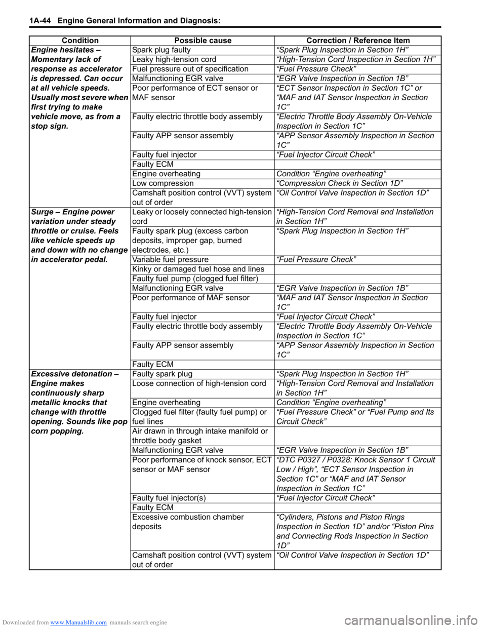
Engine hesitates –
Momentary lack of
response as accelerator
is depressed. Can occur
at all vehicle speeds.
Usually most severe when
first trying to make
vehicle move, as from a
stop sign.Spark plug faulty
“Spark Plug Inspection in Section 1H”
Leaky high-tension cord “High-Tension Cord Inspection in Section 1H”
Fuel pressure out of specification “Fuel Pressure Check”
Malfunctioning EGR valve “EGR Valve Inspection in Section 1B”
Poor performance of ECT sensor or
MAF sensor “ECT Sensor Inspection in Section 1C” or
“MAF and IAT Sensor Inspection in Section
1C”
Faulty electric throttle body assembly “Electric Throttle Body Assembly On-Vehicle
Inspection in Section 1C”
Faulty APP sensor assembly “APP Sensor Assembly Inspection in Section
1C”
Faulty fuel injector “Fuel Injector Circuit Check”
Faulty ECM
Engine overheating Condition “Engine overheating”
Low compression “Compression Check in Section 1D”
Camshaft position control (VVT) system
out of order “Oil Control Valve Inspection in Section 1D”
Surge – Engine power
variation under steady
throttle or cruise. Feels
like vehicle speeds up
and down with no change
in accelerator pedal. Leaky or loosely connected high-tension
cord
“High-Tension Cord Removal and Installation
in Section 1H”
Faulty spark plug (excess carbon
deposits, improper gap, burned
electrodes, etc.) “Spark Plug Inspection in Section 1H”
Variable fuel pressure “Fuel Pressure Check”
Kinky or damaged fuel hose and lines
Faulty fuel pump (clogged fuel filter)
Malfunctioning EGR valve “EGR Valve Inspection in Section 1B”
Poor performance of MAF sensor “MAF and IAT Sensor Inspection in Section
1C”
Faulty fuel injector “Fuel Injector Circuit Check”
Faulty electric throttle body assembly “Electric Throttle Body Assembly On-Vehicle
Inspection in Section 1C”
Faulty APP sensor assembly “APP Sensor Assembly Inspection in Section
1C”
Faulty ECM
Excessive detonation –
Engine makes
continuously sharp
metallic knocks that
change with throttle
opening. Sounds like pop
corn popping. Faulty spark plug
“Spark Plug Inspection in Section 1H”
Loose connection of high-tension cord “High-Tension Cord Removal and Installation
in Section 1H”
Engine overheating Condition “Engine overheating”
Clogged fuel filter (faulty fuel pump) or
fuel lines “Fuel Pressure Check” or “Fuel Pump and Its
Circuit Check”
Air drawn in through intake manifold or
throttle body gasket
Malfunctioning EGR valve “EGR Valve Inspection in Section 1B”
Poor performance of knock sensor, ECT
sensor or MAF sensor “DTC P0327 / P0328: Knock Sensor 1 Circuit
Low / High”, “ECT Sensor Inspection in
Section 1C” or “MAF and IAT Sensor
Inspection in Section 1C”
Faulty fuel injector(s) “Fuel Injector Circuit Check”
Faulty ECM
Excessive combustion chamber
deposits “Cylinders, Pistons and Piston Rings
Inspection in Section 1D” and/or “Piston Pins
and Connecting Rods In
spection in Section
1D”
Camshaft position control (VVT) system
out of order “Oil Control Valve Inspection in Section 1D”
Condition Possible cause Correction / Reference Item
Page 95 of 1496
Downloaded from www.Manualslib.com manuals search engine Engine General Information and Diagnosis: 1A-45
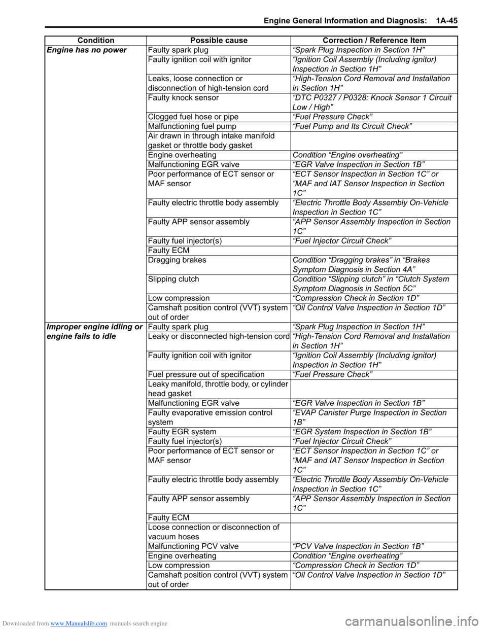
Engine has no powerFaulty spark plug “Spark Plug Inspection in Section 1H”
Faulty ignition coil with ignitor “Ignition Coil Assembly (Including ignitor)
Inspection in Section 1H”
Leaks, loose connection or
disconnection of high-tension cord “High-Tension Cord Removal and Installation
in Section 1H”
Faulty knock sensor “DTC P0327 / P0328: Knock Sensor 1 Circuit
Low / High”
Clogged fuel hose or pipe “Fuel Pressure Check”
Malfunctioning fuel pump “Fuel Pump and Its Circuit Check”
Air drawn in through intake manifold
gasket or throttle body gasket
Engine overheating Condition “Engine overheating”
Malfunctioning EGR valve “EGR Valve Inspection in Section 1B”
Poor performance of ECT sensor or
MAF sensor “ECT Sensor Inspection in Section 1C” or
“MAF and IAT Sensor Inspection in Section
1C”
Faulty electric throttle body assembly “Electric Throttle Body Assembly On-Vehicle
Inspection in Section 1C”
Faulty APP sensor assembly “APP Sensor Assembly Inspection in Section
1C”
Faulty fuel injector(s) “Fuel Injector Circuit Check”
Faulty ECM
Dragging brakes Condition “Dragging brakes” in “Brakes
Symptom Diagnosis in Section 4A”
Slipping clutch Condition “Slipping clutch” in “Clutch System
Symptom Diagnosis in Section 5C”
Low compression “Compression Check in Section 1D”
Camshaft position control (VVT) system
out of order “Oil Control Valve Inspection in Section 1D”
Improper engine idling or
engine fails to idle Faulty spark plug
“Spark Plug Inspection in Section 1H”
Leaky or disconnected high-tension cord “High-Tension Cord Removal and Installation
in Section 1H”
Faulty ignition coil with ignitor “Ignition Coil Assembly (Including ignitor)
Inspection in Section 1H”
Fuel pressure out of specification “Fuel Pressure Check”
Leaky manifold, throttle body, or cylinder
head gasket
Malfunctioning EGR valve “EGR Valve Inspection in Section 1B”
Faulty evaporative emission control
system “EVAP Canister Purge Inspection in Section
1B”
Faulty EGR system “EGR System Inspection in Section 1B”
Faulty fuel injector(s) “Fuel Injector Circuit Check”
Poor performance of ECT sensor or
MAF sensor “ECT Sensor Inspection in Section 1C” or
“MAF and IAT Sensor Inspection in Section
1C”
Faulty electric throttle body assembly “Electric Throttle Body Assembly On-Vehicle
Inspection in Section 1C”
Faulty APP sensor assembly “APP Sensor Assembly Inspection in Section
1C”
Faulty ECM
Loose connection or disconnection of
vacuum hoses
Malfunctioning PCV valve “PCV Valve Inspection in Section 1B”
Engine overheating Condition “Engine overheating”
Low compression “Compression Check in Section 1D”
Camshaft position control (VVT) system
out of order “Oil Control Valve Inspection in Section 1D”
Condition Possible cause Correction / Reference Item
Page 96 of 1496
Downloaded from www.Manualslib.com manuals search engine 1A-46 Engine General Information and Diagnosis:
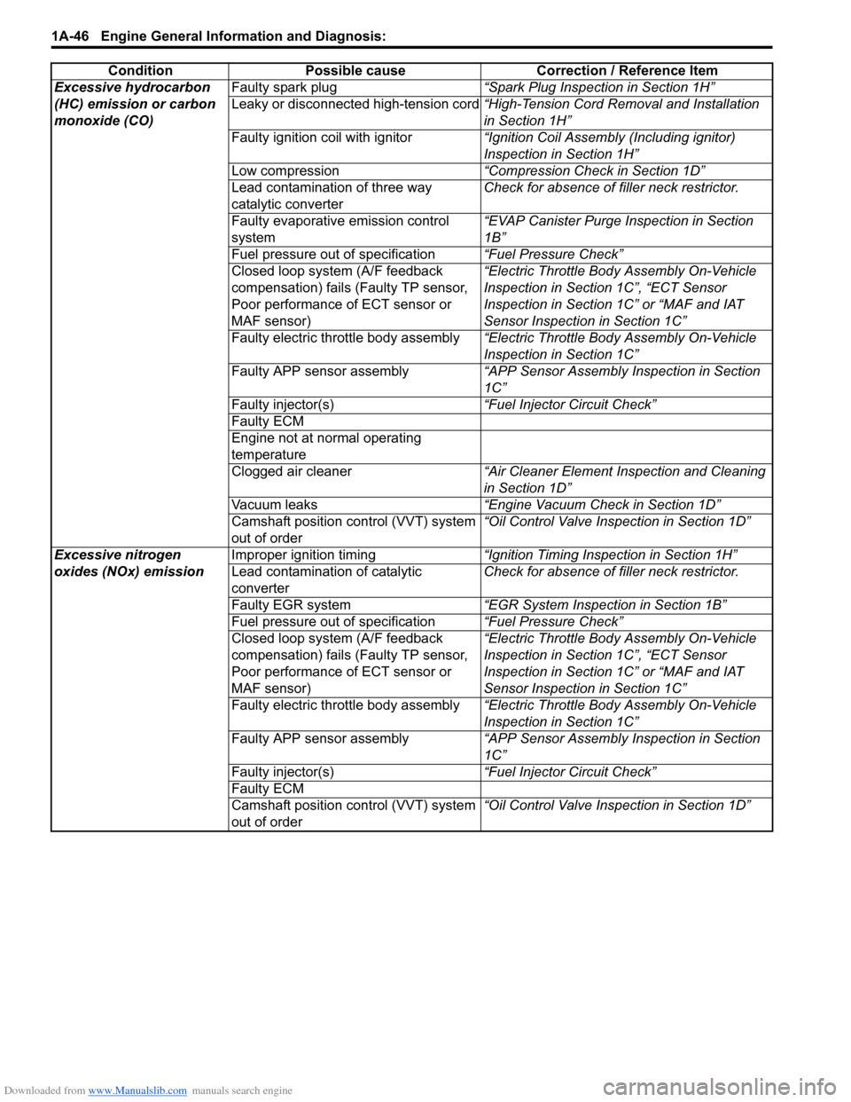
Excessive hydrocarbon
(HC) emission or carbon
monoxide (CO)Faulty spark plug
“Spark Plug Inspection in Section 1H”
Leaky or disconnected high-tension cord “High-Tension Cord Removal and Installation
in Section 1H”
Faulty ignition coil with ignitor “Ignition Coil Assembly (Including ignitor)
Inspection in Section 1H”
Low compression “Compression Check in Section 1D”
Lead contamination of three way
catalytic converter Check for absence of f
iller neck restrictor.
Faulty evaporative emission control
system “EVAP Canister Purge Inspection in Section
1B”
Fuel pressure out of specification “Fuel Pressure Check”
Closed loop system (A/F feedback
compensation) fails (Faulty TP sensor,
Poor performance of ECT sensor or
MAF sensor) “Electric Throttle Body Assembly On-Vehicle
Inspection in Section 1C”, “ECT Sensor
Inspection in Section 1C” or “MAF and IAT
Sensor Inspection in Section 1C”
Faulty electric throttle body assembly “Electric Throttle Body Assembly On-Vehicle
Inspection in Section 1C”
Faulty APP sensor assembly “APP Sensor Assembly Inspection in Section
1C”
Faulty injector(s) “Fuel Injector Circuit Check”
Faulty ECM
Engine not at normal operating
temperature
Clogged air cleaner “Air Cleaner Element Inspection and Cleaning
in Section 1D”
Vacuum leaks “Engine Vacuum Check in Section 1D”
Camshaft position control (VVT) system
out of order “Oil Control Valve Inspection in Section 1D”
Excessive nitrogen
oxides (NOx) emission Improper ignition timing
“Ignition Timing Inspection in Section 1H”
Lead contamination of catalytic
converter Check for absence of f
iller neck restrictor.
Faulty EGR system “EGR System Inspection in Section 1B”
Fuel pressure out of specification “Fuel Pressure Check”
Closed loop system (A/F feedback
compensation) fails (Faulty TP sensor,
Poor performance of ECT sensor or
MAF sensor) “Electric Throttle Body Assembly On-Vehicle
Inspection in Section 1C”, “ECT Sensor
Inspection in Section 1C” or “MAF and IAT
Sensor Inspection in Section 1C”
Faulty electric throttle body assembly “Electric Throttle Body Assembly On-Vehicle
Inspection in Section 1C”
Faulty APP sensor assembly “APP Sensor Assembly Inspection in Section
1C”
Faulty injector(s) “Fuel Injector Circuit Check”
Faulty ECM
Camshaft position control (VVT) system
out of order “Oil Control Valve Inspection in Section 1D”
Condition Possible cause Correction / Reference Item
Page 97 of 1496
Downloaded from www.Manualslib.com manuals search engine Engine General Information and Diagnosis: 1A-47
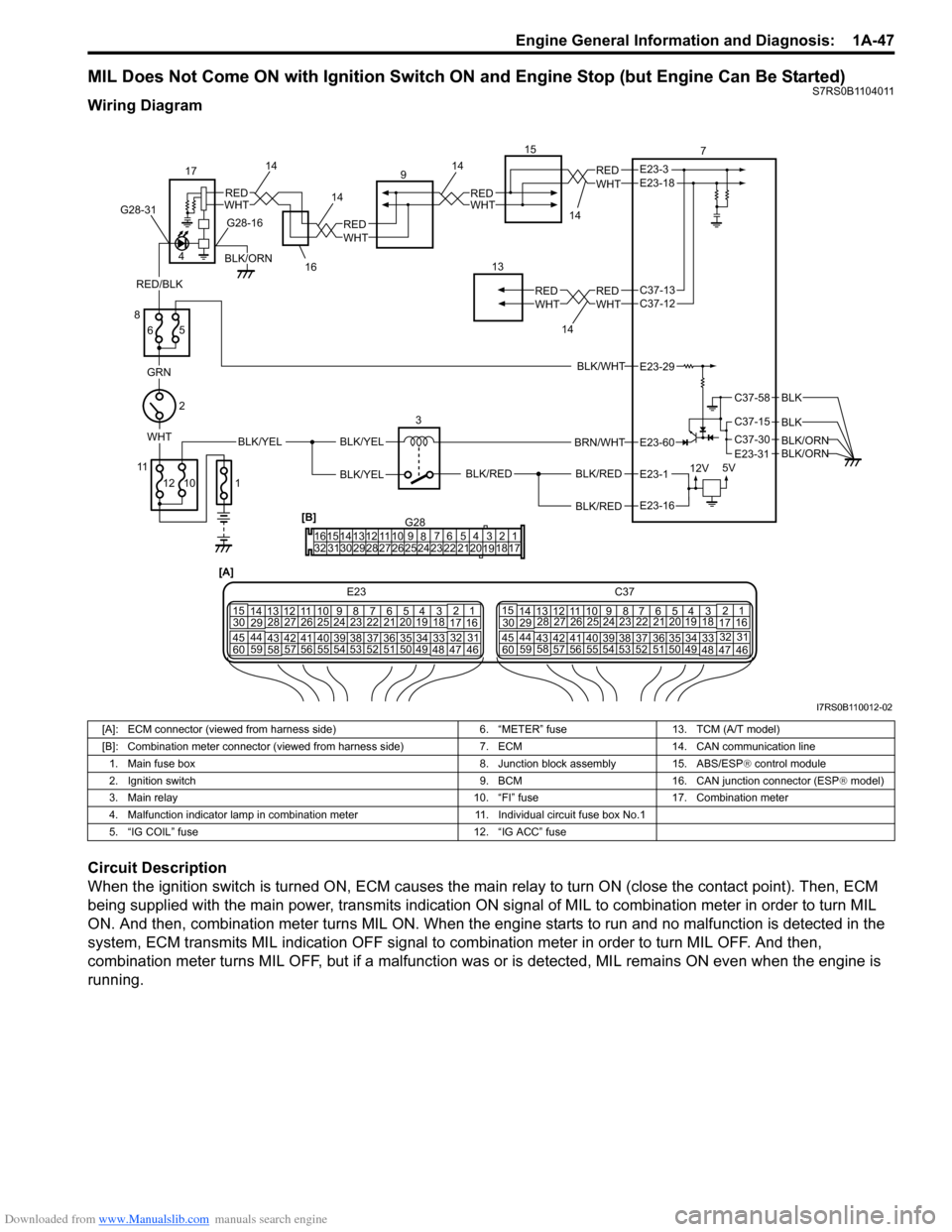
MIL Does Not Come ON with Ignition Switch ON and Engine Stop (but Engine Can Be Started)S7RS0B1104011
Wiring Diagram
Circuit Description
When the ignition switch is turned ON, ECM causes the main relay to turn ON (close the contact point). Then, ECM
being supplied with the main power, transmits indication ON si gnal of MIL to combination meter in order to turn MIL
ON. And then, combination meter turns MIL ON. When the engine starts to run and no malfunction is detected in the
system, ECM transmits MIL indication OFF signal to combination meter in order to turn MIL OFF. And then,
combination meter turns MIL OFF, but if a malfunction was or is detected, MIL remains ON even when the engine is
running.
G281234567
8
910
11
1213141516
1718
19
20
212223242526272829303132
[B]
[A]
E23 C37
34
1819
567
10
11
17
20
47 46
495051
2122
52 16
25 9
24
14
29
5557 54 53
59
60 58 2
262728
15
30
56 4832 31
34353637
4042 39 38
44
45 43 41 331
1213
238
34
1819
567
10
11
17
20
47 46
495051
2122
52 16
25 9
24
14
29
5557 54 53
59
60 58 2
262728
15
30
56 4832 31
34353637
4042 39 38
44
45 43 41 331
12
13
238
BLK/WHT
BLK/RED
BLK/RED
BRN/WHT
BLK/REDWHTBLK/YEL
GRN
12V 5V
2
3
8
6 7
E23-29
E23-3
E23-1
E23-60
E23-18
E23-16
1014
14
12
11
RED/BLK
C37-58
C37-15
C37-30
BLK
E23-31
BLK
BLK/ORNBLK/ORN
4
WHTREDWHTRED
BLK/ORN
G28-16
15
13
14
1414
G28-31
BLK/YEL
BLK/YEL
WHTRED
WHTRED
WHTREDC37-13 C37-12
WHTRED
9
17
5 1 16
I7RS0B110012-02
[A]: ECM connector (viewed from harness side)
6. “METER” fuse13. TCM (A/T model)
[B]: Combination meter connector (viewed from harness side) 7. ECM14. CAN communication line
1. Main fuse box 8. Junction block assembly15. ABS/ESP® control module
2. Ignition switch 9. BCM16. CAN junction connector (ESP® model)
3. Main relay 10. “FI” fuse17. Combination meter
4. Malfunction indicator lamp in combination meter 11. Individual circuit fuse box No.1
5. “IG COIL” fuse 12. “IG ACC” fuse
Page 98 of 1496
Downloaded from www.Manualslib.com manuals search engine 1A-48 Engine General Information and Diagnosis:
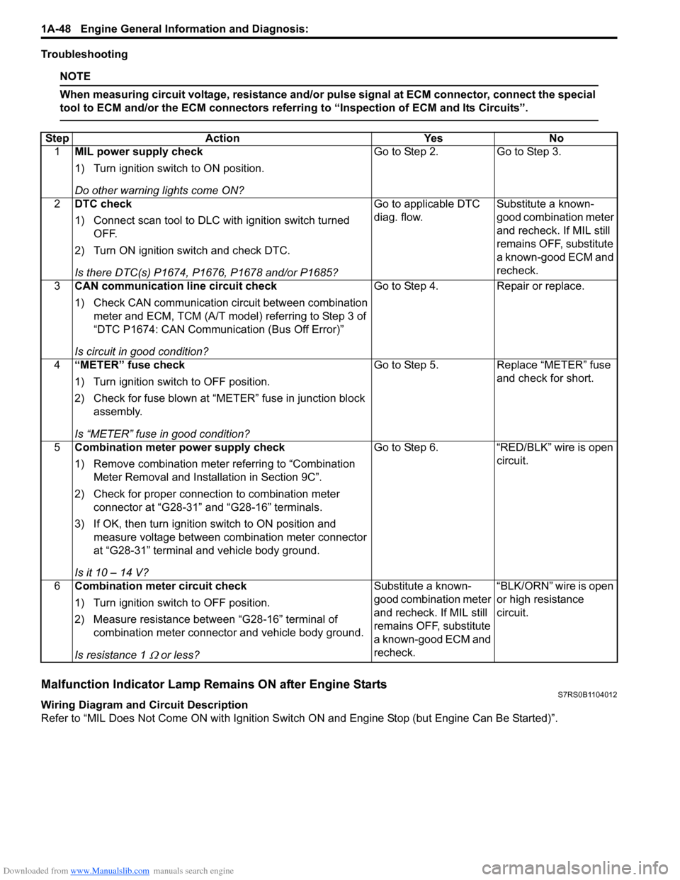
Troubleshooting
NOTE
When measuring circuit voltage, resistance and/or pulse signal at ECM connector, connect the special
tool to ECM and/or the ECM connectors referri ng to “Inspection of ECM and Its Circuits”.
Malfunction Indicator Lamp Remains ON after Engine StartsS7RS0B1104012
Wiring Diagram and Circuit Description
Refer to “MIL Does Not Come ON wit h Ignition Switch ON and Engine Stop (but Engine Can Be Started)”.
Step
Action YesNo
1 MIL power supply check
1) Turn ignition switch to ON position.
Do other warning lights come ON? Go to Step 2.
Go to Step 3.
2 DTC check
1) Connect scan tool to DLC with ignition switch turned
OFF.
2) Turn ON ignition switch and check DTC.
Is there DTC(s) P1674, P1676, P1678 and/or P1685? Go to applicable DTC
diag. flow.
Substitute a known-
good combination meter
and recheck. If MIL still
remains OFF, substitute
a known-good ECM and
recheck.
3 CAN communication line circuit check
1) Check CAN communication circuit between combination
meter and ECM, TCM (A/T model) referring to Step 3 of
“DTC P1674: CAN Communication (Bus Off Error)”
Is circuit in good condition? Go to Step 4.
Repair or replace.
4 “METER” fuse check
1) Turn ignition switch to OFF position.
2) Check for fuse blown at “M ETER” fuse in junction block
assembly.
Is “METER” fuse in good condition? Go to Step 5.
Replace “METER” fuse
and check for short.
5 Combination meter power supply check
1) Remove combination meter referring to “Combination
Meter Removal and Installation in Section 9C”.
2) Check for proper connection to combination meter connector at “G28-31” and “G28-16” terminals.
3) If OK, then turn ignition switch to ON position and measure voltage between combination meter connector
at “G28-31” terminal and vehicle body ground.
Is it 10 – 14 V? Go to Step 6.
“RED/BLK” wire is open
circuit.
6 Combination meter circuit check
1) Turn ignition switch to OFF position.
2) Measure resistance between “G28-16” terminal of
combination meter connector and vehicle body ground.
Is resistance 1
Ω or less? Substitute a known-
good combination meter
and recheck. If MIL still
remains OFF, substitute
a known-good ECM and
recheck.
“BLK/ORN” wire is open
or high resistance
circuit.
Page 99 of 1496
Downloaded from www.Manualslib.com manuals search engine Engine General Information and Diagnosis: 1A-49
Troubleshooting
NOTE
When measuring circuit voltage, resistance and/or pulse signal at ECM connector, connect the special
tool to ECM and/or the ECM connectors referri ng to “Inspection of ECM and Its Circuits”.
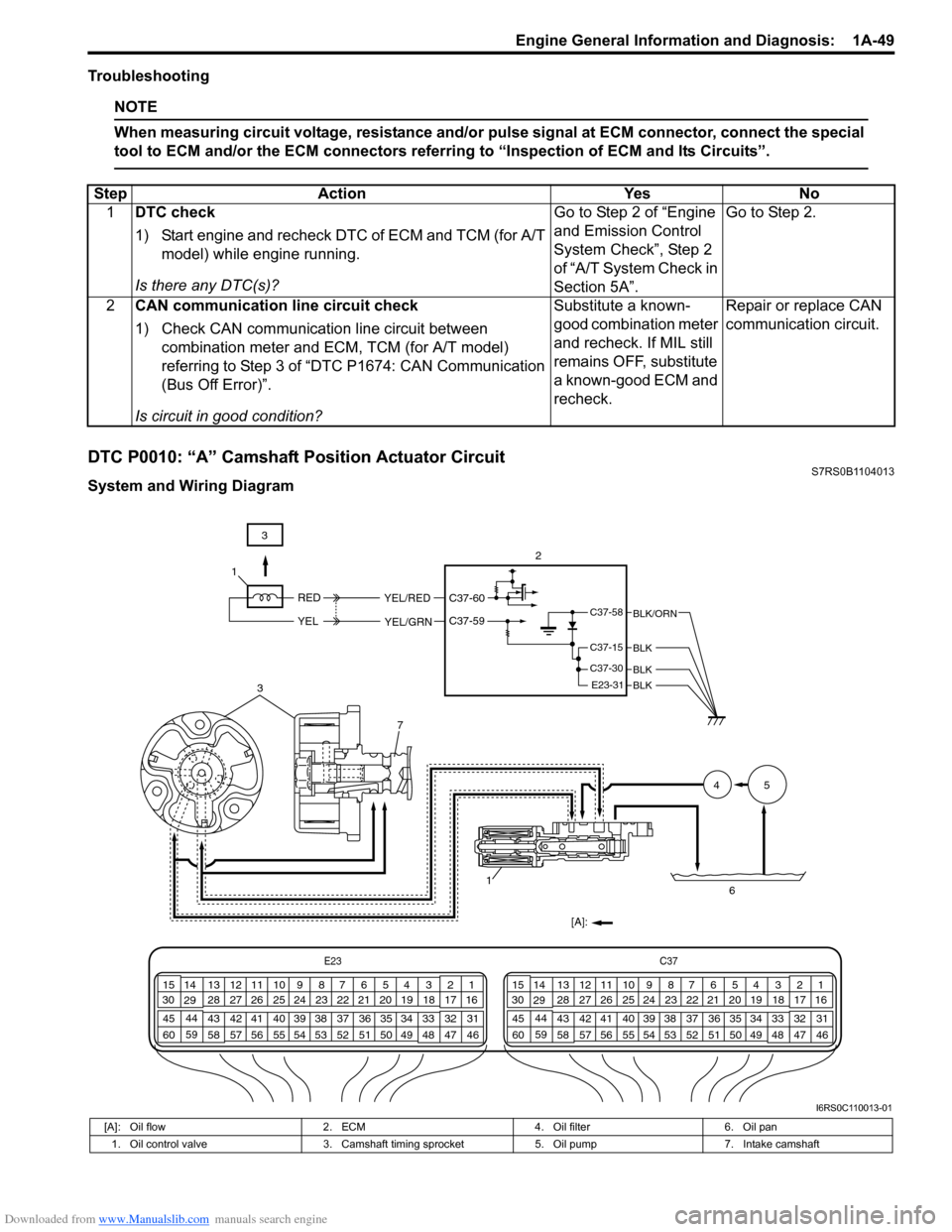
DTC P0010: “A” Camshaft Position Actuator CircuitS7RS0B1104013
System and Wiring DiagramStep Action Yes No
1 DTC check
1) Start engine and recheck DTC of ECM and TCM (for A/T
model) while engine running.
Is there any DTC(s)? Go to Step 2 of “Engine
and Emission Control
System Check”, Step 2
of “A/T System Check in
Section 5A”.Go to Step 2.
2 CAN communication line circuit check
1) Check CAN communication line circuit between
combination meter and ECM, TCM (for A/T model)
referring to Step 3 of “DTC P1674: CAN Communication
(Bus Off Error)”.
Is circuit in good condition? Substitute a known-
good combination meter
and recheck. If MIL still
remains OFF, substitute
a known-good ECM and
recheck.
Repair or replace CAN
communication circuit.
3
7
1[A]: 45
6
C37-58
C37-15
C37-30
E23-31BLK
BLK
BLK/ORN
RED
YEL
YEL/RED
YEL/GRN
C37-60
C37-59
3 2
1
E23 C37
34
1819
567
1011
17
20
47 46
495051
2122
52 16
25 9
24
14
29
55
57 54 53
59
60 58 2
262728
15
30
56 4832 31
34353637
40
42 39 38
44
45 43 41 331
1213
238
34
1819
567
1011
17
20
47 46
495051
2122
52 16
25 9
24
14
29
55
57 54 53
59
60 58 2
262728
15
30
56 4832 31
34353637
40
42 39 38
44
45 43 41 331
1213
238
BLK
I6RS0C110013-01
[A]: Oil flow
2. ECM4. Oil filter6. Oil pan
1. Oil control valve 3. Camshaft timing sprocket5. Oil pump7. Intake camshaft