cat SUZUKI SWIFT 2007 2.G Service Manual Online
[x] Cancel search | Manufacturer: SUZUKI, Model Year: 2007, Model line: SWIFT, Model: SUZUKI SWIFT 2007 2.GPages: 1496, PDF Size: 34.44 MB
Page 143 of 1496
Downloaded from www.Manualslib.com manuals search engine Engine General Information and Diagnosis: 1A-93
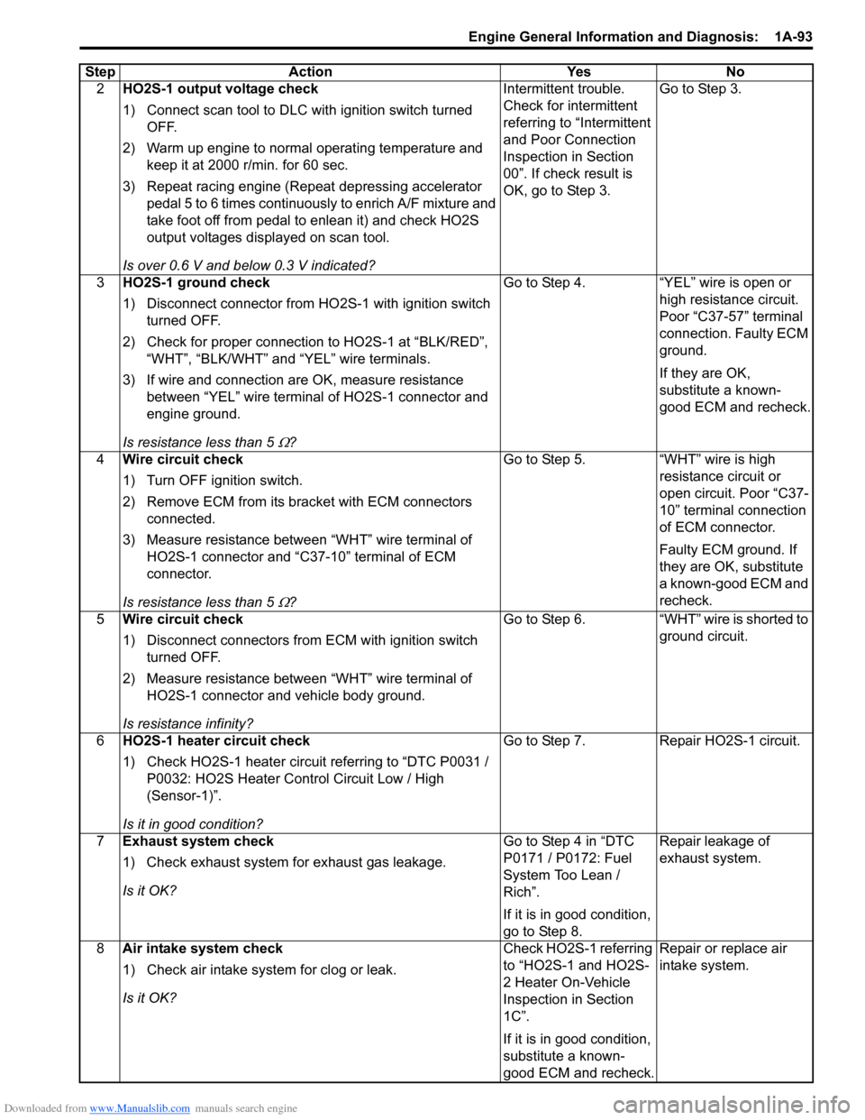
2HO2S-1 output voltage check
1) Connect scan tool to DLC with ignition switch turned
OFF.
2) Warm up engine to normal operating temperature and keep it at 2000 r/min. for 60 sec.
3) Repeat racing engine (Repeat depressing accelerator pedal 5 to 6 times continuous ly to enrich A/F mixture and
take foot off from pedal to enlean it) and check HO2S
output voltages displayed on scan tool.
Is over 0.6 V and below 0.3 V indicated? Intermittent trouble.
Check for intermittent
referring to “Intermittent
and Poor Connection
Inspection in Section
00”. If check result is
OK, go to Step 3.
Go to Step 3.
3 HO2S-1 ground check
1) Disconnect connector from HO 2S-1 with ignition switch
turned OFF.
2) Check for proper connection to HO2S-1 at “BLK/RED”, “WHT”, “BLK/WHT” and “YEL” wire terminals.
3) If wire and connection are OK, measure resistance between “YEL” wire terminal of HO2S-1 connector and
engine ground.
Is resistance less than 5
Ω? Go to Step 4. “YEL” wire is open or
high resistance circuit.
Poor “C37-57” terminal
connection. Faulty ECM
ground.
If they are OK,
substitute a known-
good ECM and recheck.
4 Wire circuit check
1) Turn OFF ignition switch.
2) Remove ECM from its br acket with ECM connectors
connected.
3) Measure resistance between “WHT” wire terminal of HO2S-1 connector and “C37-10” terminal of ECM
connector.
Is resistance less than 5
Ω? Go to Step 5. “WHT” wire is high
resistance circuit or
open circuit. Poor “C37-
10” terminal connection
of ECM connector.
Faulty ECM ground. If
they are OK, substitute
a known-good ECM and
recheck.
5 Wire circuit check
1) Disconnect connectors from ECM with ignition switch
turned OFF.
2) Measure resistance between “WHT” wire terminal of HO2S-1 connector and vehicle body ground.
Is resistance infinity? Go to Step 6. “WHT” wire is shorted to
ground circuit.
6 HO2S-1 heater circuit check
1) Check HO2S-1 heater circuit referring to “DTC P0031 /
P0032: HO2S Heater Control Circuit Low / High
(Sensor-1)”.
Is it in good condition? Go to Step 7. Repair HO2S-1 circuit.
7 Exhaust system check
1) Check exhaust system for exhaust gas leakage.
Is it OK? Go to Step 4 in “DTC
P0171 / P0172: Fuel
System Too Lean /
Rich”.
If it is in good condition,
go to Step 8.Repair leakage of
exhaust system.
8 Air intake system check
1) Check air intake system for clog or leak.
Is it OK? Check HO2S-1 referring
to “HO2S-1 and HO2S-
2 Heater On-Vehicle
Inspection in Section
1C”.
If it is in good condition,
substitute a known-
good ECM and recheck.Repair or replace air
intake system.
Step Action Yes No
Page 145 of 1496
Downloaded from www.Manualslib.com manuals search engine Engine General Information and Diagnosis: 1A-95
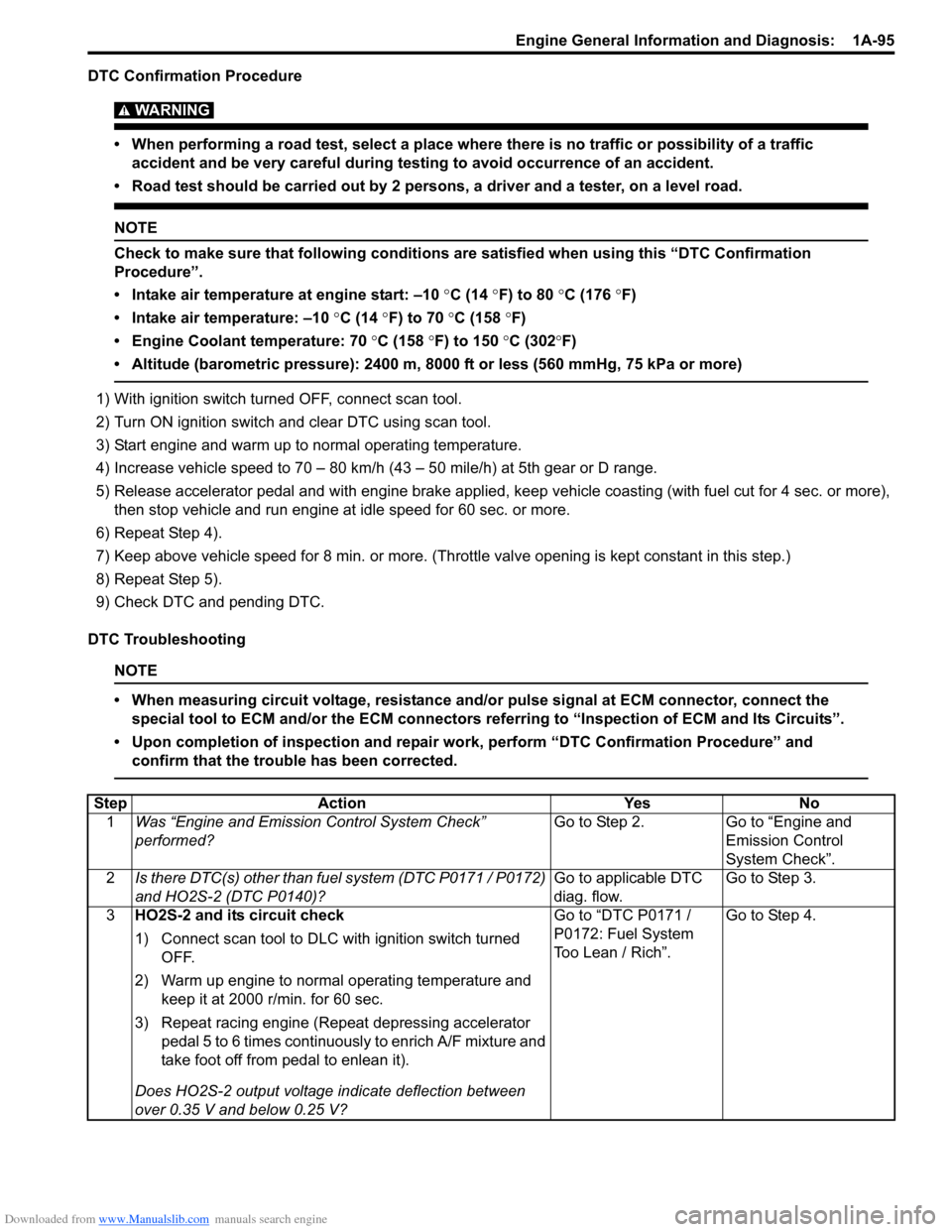
DTC Confirmation Procedure
WARNING!
• When performing a road test, select a place where there is no traffic or possibility of a traffic accident and be very careful during testing to avoid occurrence of an accident.
• Road test should be carried out by 2 persons, a driver and a tester, on a level road.
NOTE
Check to make sure that following conditions ar e satisfied when using this “DTC Confirmation
Procedure”.
• Intake air temperature at engine start: –10 °C (14 ° F) to 80 °C (176 °F)
• Intake air temperature: –10 °C (14 °F) to 70 °C (158 °F)
• Engine Coolant temperature: 70 °C (158 °F) to 150 °C (302 °F)
• Altitude (barometric pressure): 2400 m, 8000 ft or less (560 mmHg, 75 kPa or more)
1) With ignition switch turned OFF, connect scan tool.
2) Turn ON ignition switch and clear DTC using scan tool.
3) Start engine and warm up to normal operating temperature.
4) Increase vehicle speed to 70 – 80 km/h (43 – 50 mile/h) at 5th gear or D range.
5) Release accelerator pedal and with engine brake applied, ke ep vehicle coasting (with fuel cut for 4 sec. or more),
then stop vehicle and run engine at idle speed for 60 sec. or more.
6) Repeat Step 4).
7) Keep above vehicle speed for 8 min. or more. (Throt tle valve opening is kept constant in this step.)
8) Repeat Step 5).
9) Check DTC and pending DTC.
DTC Troubleshooting
NOTE
• When measuring circuit voltage, resistance and/ or pulse signal at ECM connector, connect the
special tool to ECM and/or the ECM connectors re ferring to “Inspection of ECM and Its Circuits”.
• Upon completion of inspection and repair work, perform “DTC Confirmation Procedure” and confirm that the trouble has been corrected.
Step Action YesNo
1 Was “Engine and Emission Control System Check”
performed? Go to Step 2.
Go to “Engine and
Emission Control
System Check”.
2 Is there DTC(s) other than fuel system (DTC P0171 / P0172)
and HO2S-2 (DTC P0140)? Go to applicable DTC
diag. flow.Go to Step 3.
3 HO2S-2 and its circuit check
1) Connect scan tool to DLC with ignition switch turned
OFF.
2) Warm up engine to normal operating temperature and keep it at 2000 r/min. for 60 sec.
3) Repeat racing engine (Repeat depressing accelerator pedal 5 to 6 times continuous ly to enrich A/F mixture and
take foot off from pedal to enlean it).
Does HO2S-2 output voltage indicate deflection between
over 0.35 V and below 0.25 V? Go to “DTC P0171 /
P0172: Fuel System
Too Lean / Rich”.
Go to Step 4.
Page 148 of 1496
Downloaded from www.Manualslib.com manuals search engine 1A-98 Engine General Information and Diagnosis:
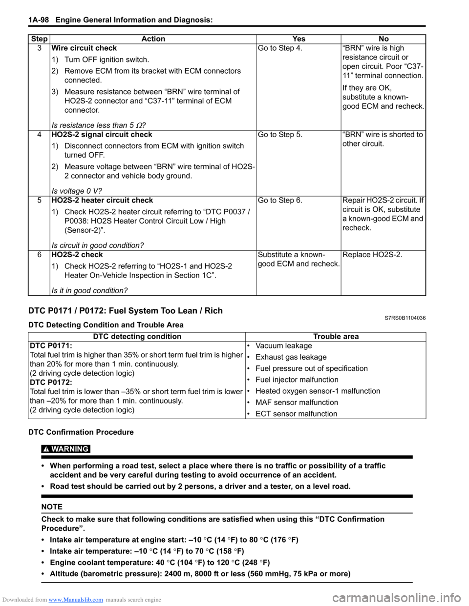
DTC P0171 / P0172: Fuel System Too Lean / RichS7RS0B1104036
DTC Detecting Condition and Trouble Area
DTC Confirmation Procedure
WARNING!
• When performing a road test, select a place where there is no traffic or possibility of a traffic accident and be very careful during testing to avoid occurrence of an accident.
• Road test should be carried out by 2 persons, a driver and a tester, on a level road.
NOTE
Check to make sure that following conditions ar e satisfied when using this “DTC Confirmation
Procedure”.
• Intake air temperature at engine start: –10 °C (14 ° F) to 80 °C (176 °F)
• Intake air temperature: –10 °C (14 °F) to 70 °C (158 °F)
• Engine coolant temperature: 40 °C (104 °F) to 120 °C (248 °F)
• Altitude (barometric pressure): 2400 m, 8000 ft or less (560 mmHg, 75 kPa or more)
3 Wire circuit check
1) Turn OFF ignition switch.
2) Remove ECM from its br acket with ECM connectors
connected.
3) Measure resistance between “BRN” wire terminal of HO2S-2 connector and “C37-11” terminal of ECM
connector.
Is resistance less than 5
Ω? Go to Step 4. “BRN” wire is high
resistance circuit or
open circuit. Poor “C37-
11” terminal connection.
If they are OK,
substitute a known-
good ECM and recheck.
4 HO2S-2 signal circuit check
1) Disconnect connectors from ECM with ignition switch
turned OFF.
2) Measure voltage between “BRN” wire terminal of HO2S- 2 connector and vehicle body ground.
Is voltage 0 V? Go to Step 5. “BRN” wire is shorted to
other circuit.
5 HO2S-2 heater circuit check
1) Check HO2S-2 heater circuit referring to “DTC P0037 /
P0038: HO2S Heater Control Circuit Low / High
(Sensor-2)”.
Is circuit in good condition? Go to Step 6. Repair HO2S-2 circuit. If
circuit is OK, substitute
a known-good ECM and
recheck.
6 HO2S-2 check
1) Check HO2S-2 referring to “HO2S-1 and HO2S-2
Heater On-Vehicle Inspection in Section 1C”.
Is it in good condition? Substitute a known-
good ECM and recheck.
Replace HO2S-2.
Step Action Yes No
DTC detecting condition
Trouble area
DTC P0171:
Total fuel trim is higher than 35% or short term fuel trim is higher
than 20% for more than 1 min. continuously.
(2 driving cycle detection logic)
DTC P0172:
Total fuel trim is lower than –35% or short term fuel trim is lower
than –20% for more than 1 min. continuously.
(2 driving cycle detection logic) • Vacuum leakage
• Exhaust gas leakage
• Fuel pressure out of specification
• Fuel injector malfunction
• Heated oxygen sensor-1 malfunction
• MAF sensor malfunction
• ECT sensor malfunction
Page 151 of 1496
Downloaded from www.Manualslib.com manuals search engine Engine General Information and Diagnosis: 1A-101
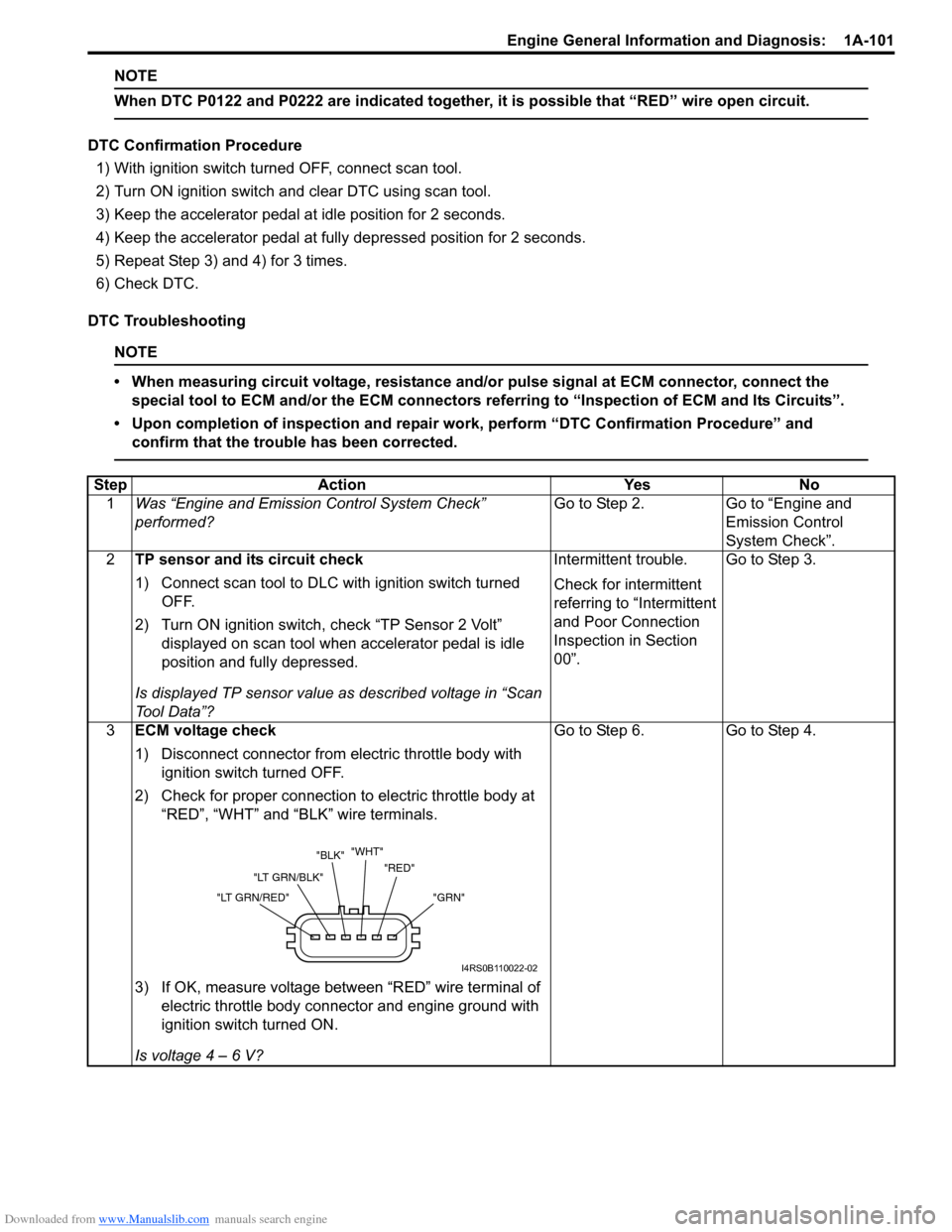
NOTE
When DTC P0122 and P0222 are indicated together, it is possible that “RED” wire open circuit.
DTC Confirmation Procedure
1) With ignition switch turned OFF, connect scan tool.
2) Turn ON ignition switch and clear DTC using scan tool.
3) Keep the accelerator pedal at idle position for 2 seconds.
4) Keep the accelerator pedal at fully depressed position for 2 seconds.
5) Repeat Step 3) and 4) for 3 times.
6) Check DTC.
DTC Troubleshooting
NOTE
• When measuring circuit voltage, resistance and/ or pulse signal at ECM connector, connect the
special tool to ECM and/or the ECM connectors re ferring to “Inspection of ECM and Its Circuits”.
• Upon completion of inspection and repair work, perform “DTC Confirmation Procedure” and confirm that the trouble has been corrected.
Step Action YesNo
1 Was “Engine and Emission Control System Check”
performed? Go to Step 2.
Go to “Engine and
Emission Control
System Check”.
2 TP sensor and its circuit check
1) Connect scan tool to DLC with ignition switch turned
OFF.
2) Turn ON ignition switch, check “TP Sensor 2 Volt” displayed on scan tool when accelerator pedal is idle
position and fully depressed.
Is displayed TP sensor value as described voltage in “Scan
To o l D a t a ” ? Intermittent trouble.
Check for intermittent
referring to “Intermittent
and Poor Connection
Inspection in Section
00”.
Go to Step 3.
3 ECM voltage check
1) Disconnect connector from electric throttle body with
ignition switch turned OFF.
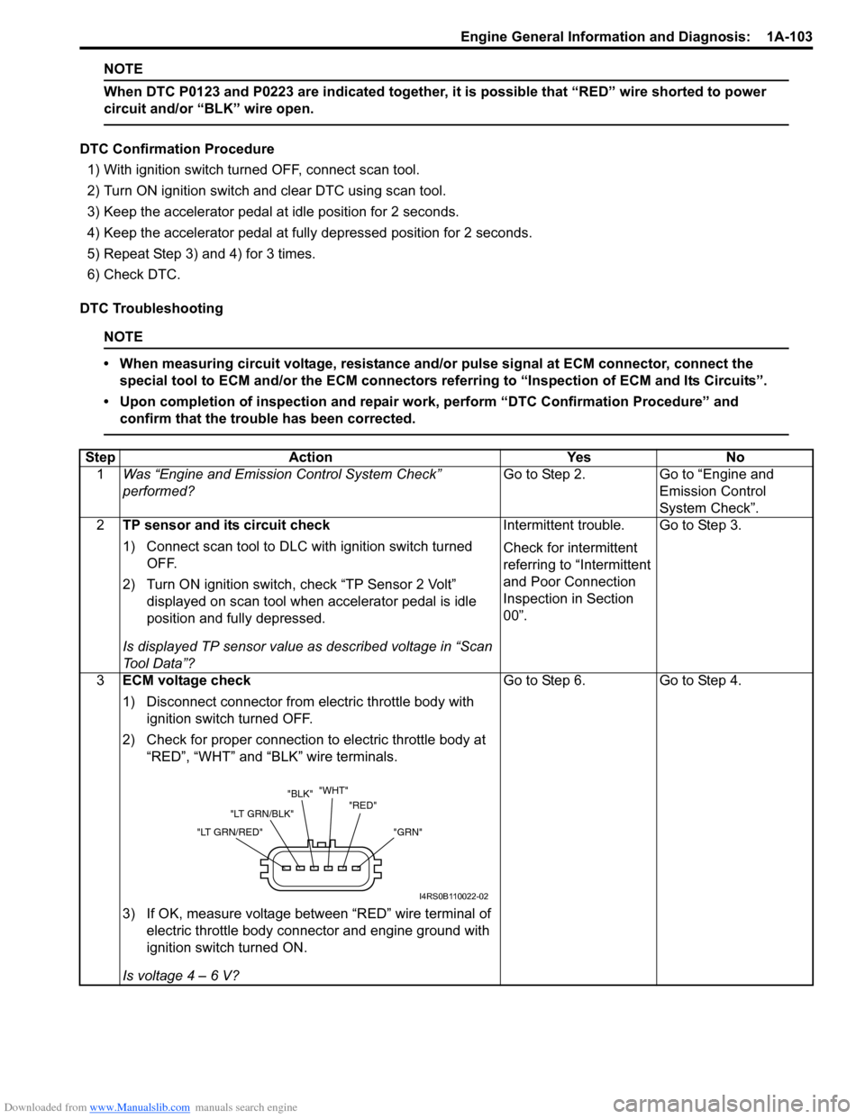
2) Check for proper connection to electric throttle body at “RED”, “WHT” and “BLK” wire terminals.
3) If OK, measure voltage between “RED” wire terminal of electric throttle body connector and engine ground with
ignition switch turned ON.
Is voltage 4 – 6 V? Go to Step 6.
Go to Step 4.
"GRN"
"RED"
"WHT"
"BLK"
"LT GRN/BLK"
"LT GRN/RED"
I4RS0B110022-02
Page 153 of 1496
Downloaded from www.Manualslib.com manuals search engine Engine General Information and Diagnosis: 1A-103
NOTE
When DTC P0123 and P0223 are indicated together, it is possible that “RED” wire shorted to power
circuit and/or “BLK” wire open.
DTC Confirmation Procedure
1) With ignition switch turned OFF, connect scan tool.
2) Turn ON ignition switch and clear DTC using scan tool.
3) Keep the accelerator pedal at idle position for 2 seconds.
4) Keep the accelerator pedal at fully depressed position for 2 seconds.
5) Repeat Step 3) and 4) for 3 times.
6) Check DTC.
DTC Troubleshooting
NOTE
• When measuring circuit voltage, resistance and/ or pulse signal at ECM connector, connect the
special tool to ECM and/or the ECM connectors re ferring to “Inspection of ECM and Its Circuits”.
• Upon completion of inspection and repair work, perform “DTC Confirmation Procedure” and confirm that the trouble has been corrected.
Step Action YesNo
1 Was “Engine and Emission Control System Check”
performed? Go to Step 2.
Go to “Engine and
Emission Control
System Check”.
2 TP sensor and its circuit check
1) Connect scan tool to DLC with ignition switch turned
OFF.
2) Turn ON ignition switch, check “TP Sensor 2 Volt” displayed on scan tool when accelerator pedal is idle
position and fully depressed.
Is displayed TP sensor value as described voltage in “Scan
To o l D a t a ” ? Intermittent trouble.
Check for intermittent
referring to “Intermittent
and Poor Connection
Inspection in Section
00”.
Go to Step 3.
3 ECM voltage check
1) Disconnect connector from electric throttle body with
ignition switch turned OFF.
2) Check for proper connection to electric throttle body at “RED”, “WHT” and “BLK” wire terminals.
3) If OK, measure voltage between “RED” wire terminal of electric throttle body connector and engine ground with
ignition switch turned ON.
Is voltage 4 – 6 V? Go to Step 6.
Go to Step 4.
"GRN"
"RED"
"WHT"
"BLK"
"LT GRN/BLK"
"LT GRN/RED"
I4RS0B110022-02
Page 155 of 1496
Downloaded from www.Manualslib.com manuals search engine Engine General Information and Diagnosis: 1A-105
DTC P0300 / P0301 / P0302 / P0303 / P0304: Random / Multiple Cylinder Misfire Detected / Cylinder 1
/ Cylinder 2 / Cylinder 3 / Cylinder 4 Misfire Detected
S7RS0B1104039
System Description
ECM measures the angle of the crankshaft based on the pulse signal from the CKP sensor and CMP sensor for each
cylinder. If it detects a large change in the angle speed of the crankshaft, it concludes occurrence of a misfire. When
the number of misfire is counted by ECM beyond the DTC de tecting condition, it determines the cylinder where the
misfire occurred and output it as DTC.
DTC Detecting Condition and Trouble Area
DTC Confirmation Procedure
WARNING!
• When performing a road test, select a place where there is no traffic or possibility of a traffic accident and be very careful during testing to avoid occurrence of an accident.
• Road test should be carried out by 2 persons, a driver and a tester, on a level road.
NOTE
Check to make sure that following conditions ar e satisfied when using this “DTC Confirmation
Procedure”.
• Intake air temperature at engine start: –10 °C (14 ° F) to 80 °C (176 °F)
• Intake air temperature: –10 °C (14 °F) to 70 °C (158 °F)
• Engine coolant temp.: –10 °C, 14 °F or higher
• Altitude (barometric pressure): 2400 m, 8000 ft or less (560 mmHg, 75 kPa or more)
1) With ignition switch turned OFF, connect scan tool.
2) Turn ON ignition switch and print Freeze Frame Data or write them down using scan tool.
3) Clear DTC using scan tool.
4) Drive vehicle under freeze frame data condition as noted for 1 min. or more.
5) Stop vehicle and check DTC and pending DTC. 11
Electric throttle body check
1) Check TP sensor referring to “Throttle Position Sensor
Performance Check” under “Electric Throttle Body
Assembly On-Vehicle Inspection in Section 1C”.
Is output voltage within specified value? Substitute a known-
good ECM and recheck.
Replace electric throttle
body.
Step Action Yes No
DTC detecting condition
Trouble area
DTC P0300:
• Misfire, which causes catalyst to overheat during 200 engine revolutions, is detected at 2 or more cylinders. (MIL flashes as lo ng as this misfire occurs continuously.)
or
• Misfire, which affects exhaust emission adv ersely during 1000 engine revolution, is
detected at 2 or more cylinders. (2 driving cycle detection logic) • Ignition system
• Fuel injector and its circuit
• Fuel pressure
• EGR system
• Abnormal air drawn in
• Engine compression
• Valve lash adjuster
• Valve timing
• Fuel shortage
• Exhaust system
• Fuel of poor quality
DTC P0301, P0302, P0303, P0304:
• Misfire, which causes catalyst to overheat during 200 engine revolutions, is detected
at 1 cylinder. (MIL flashes as long as this misfire occurs continuously.)
or
• Misfire, which affects exhaust emission adv ersely during 1000 engine revolution, is
detected at 1 cylinder. (2 driving cycle detection logic)
Page 156 of 1496
Downloaded from www.Manualslib.com manuals search engine 1A-106 Engine General Information and Diagnosis:
DTC Troubleshooting
NOTE
• When measuring circuit voltage, resistance and/or pulse signal at ECM connector, connect the
special tool to ECM and/or the ECM connectors re ferring to “Inspection of ECM and Its Circuits”.
• Upon completion of inspection and repair work, perform “DTC Confirmation Procedure” and confirm that the trouble has been corrected.
Step Action YesNo
1 Was “Engine and Emission Control System Check”
performed? Go to Step 2.
Go to “Engine and
Emission Control
System Check”.
2 Does fuel level meter in dicate “E” level (empty)? Add fuel and recheck. Go to Step 3.
3 Fuel quality check
1) Check that there is fuel of good quality in the fuel tank.
Is it OK? Go to Step 4.
Clean in fuel system
circuit and change fuel.
4 Ignition system check
1) Check spark plug and ignition spark of cylinder where
misfire occurs, referring to “Spark Plug Inspection in
Section 1H” and “Ignition Spark Test in Section 1H”.
Are they in good condition? Go to Step 5.
Faulty ignition coil, wire
harness, spark plug or
other system parts.
5 Fuel injector circuit check
1) Using sound scope, check each injector operating sound
at engine cranking or idling.
Do all injectors ma ke operating sound? Go to Step 6.
Check coupler
connection and wire
harness of injector not
making operating sound
and injector itself. If OK,
substitute a known-
good ECM and recheck.
6 Fuel pressure check
1) Check fuel pressure referring to “Fuel Pressure Check”.
Is check result satisfactory? Go to Step 7.
Repair or replace fuel
system.
7 Fuel injector check
1) Check fuel injector(s) re ferring to “Fuel Injector
Inspection in Section 1G”.
Is check result satisfactory? Go to Step 8.
Replace defective
injector.
8 Ignition timing check
1) Check ignition timing referring to “Ignition Timing
Inspection in Section 1H”.
Is check result satisfactory? Go to Step 9.
Check related sensors.
9 EGR system check
1) Check EGR system referring to “EGR System Inspection
in Section 1B”.
Is check result satisfactory? Go to Step 10. Repair or replace EGR
system.
10 Exhaust system check
1) Check exhaust system for exhaust gas clogged.
Is it OK? Go to Step 11. Repair clogged of
exhaust system.
Page 160 of 1496
Downloaded from www.Manualslib.com manuals search engine 1A-110 Engine General Information and Diagnosis:
DTC Troubleshooting
NOTE
• When measuring circuit voltage, resistance and/or pulse signal at ECM connector, connect the
special tool to ECM and/or the ECM connectors re ferring to “Inspection of ECM and Its Circuits”.
• Upon completion of inspection and repair work, perform “DTC Confirmation Procedure” and confirm that the trouble has been corrected.
Step Action YesNo
1 Was “Engine and Emission Control System Check”
performed? Go to Step 2.
Go to “Engine and
Emission Control
System Check”.
2 CKP sensor and connector for proper installation check
Is CKP sensor installed properly and connector connected
securely? Go to Step 3.
Correct.
3 Wire harness and connection check
1) Disconnect connector from CKP sensor with ignition
switch turned OFF.
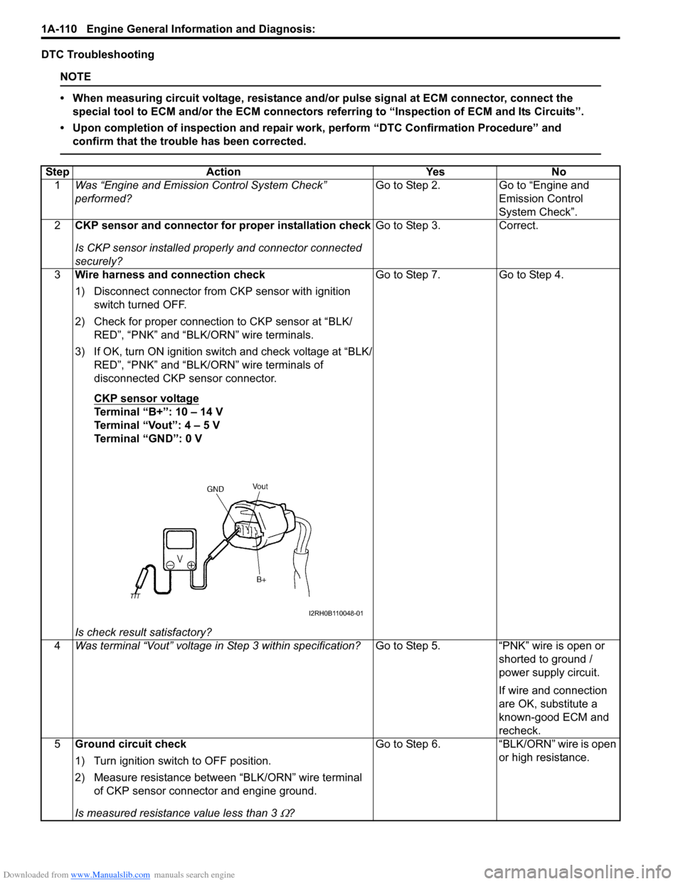
2) Check for proper connection to CKP sensor at “BLK/ RED”, “PNK” and “BLK/ORN” wire terminals.
3) If OK, turn ON ignition switch and check voltage at “BLK/ RED”, “PNK” and “BLK/ORN” wire terminals of
disconnected CKP sensor connector.
CKP sensor voltage
Terminal “B+”: 10 – 14 V
Terminal “Vout”: 4 – 5 V
Terminal “GND”: 0 V
Is check result satisfactory? Go to Step 7. Go to Step 4.
4 Was terminal “Vout” voltage in Step 3 within specification? Go to Step 5. “PNK” wire is open or
shorted to ground /
power supply circuit.
If wire and connection
are OK, substitute a
known-good ECM and
recheck.
5 Ground circuit check
1) Turn ignition switch to OFF position.
2) Measure resistance between “BLK/ORN” wire terminal
of CKP sensor connector and engine ground.
Is measured resistance value less than 3
Ω? Go to Step 6. “BLK/ORN” wire is open
or high resistance.
I2RH0B110048-01
Page 161 of 1496
Downloaded from www.Manualslib.com manuals search engine Engine General Information and Diagnosis: 1A-111
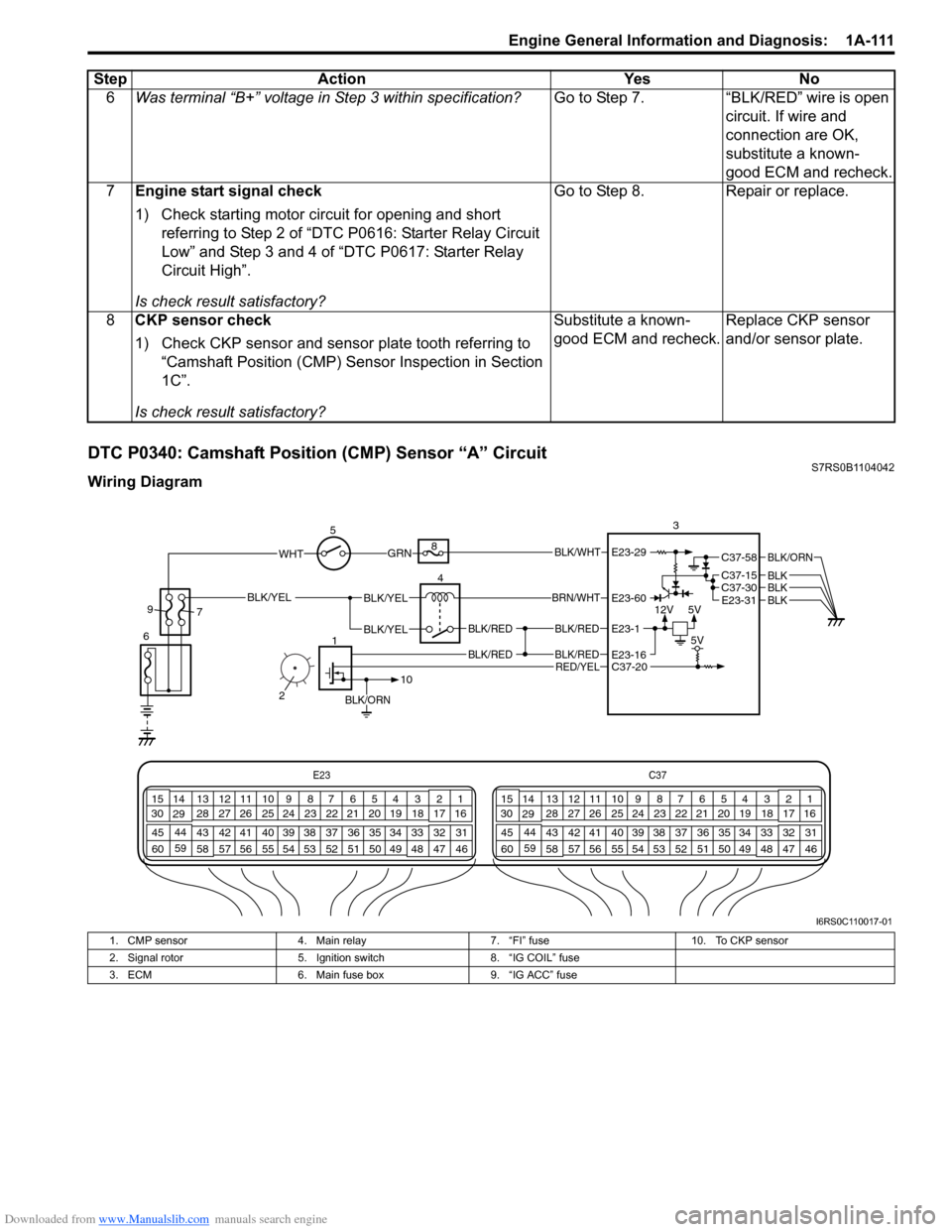
DTC P0340: Camshaft Position (CMP) Sensor “A” CircuitS7RS0B1104042
Wiring Diagram6
Was terminal “B+” voltage in Step 3 within specification? Go to Step 7. “BLK/RED” wire is open
circuit. If wire and
connection are OK,
substitute a known-
good ECM and recheck.
7 Engine start signal check
1) Check starting motor circuit for opening and short
referring to Step 2 of “DTC P0616: Starter Relay Circuit
Low” and Step 3 and 4 of “DTC P0617: Starter Relay
Circuit High”.
Is check result satisfactory? Go to Step 8. Repair or replace.
8 CKP sensor check
1) Check CKP sensor and sensor plate tooth referring to
“Camshaft Position (CMP) Sensor Inspection in Section
1C”.
Is check result satisfactory? Substitute a known-
good ECM and recheck.
Replace CKP sensor
and/or sensor plate.
Step Action Yes No
E23
C37
34
1819
567
1011
17
20
47 46
495051
2122
52 16
25 9
24
14
29
55
57 54 53
59
60 58 2
262728
15
30
56 4832 31
34353637
40
42 39 38
44
45 43 41 331
1213
238
34
1819
567
1011
17
20
47 46
495051
2122
52 16
25 9
24
14
29
55
57 54 53
59
60 58 2
262728
15
30
56 4832 31
34353637
40
42 39 38
44
45 43 41 331
1213
238
12V
5V
BLK/RED
BLK/RED
BLK/YELBLK/YEL
BLK/YEL
BRN/WHT
5
6 4
8
3
C37-30C37-15
C37-58
E23-31
BLK/ORN
BLKBLKBLK
BLK/RED
BLK/RED
E23-16
E23-60
E23-1
BLK/ORN
1
10
C37-20 5V
GRNBLK/WHT
9
7
RED/YEL
2
WHTE23-29
I6RS0C110017-01
1. CMP sensor 4. Main relay 7. “FI” fuse 10. To CKP sensor
2. Signal rotor 5. Ignition switch 8. “IG COIL” fuse
3. ECM 6. Main fuse box 9. “IG ACC” fuse
Page 162 of 1496
Downloaded from www.Manualslib.com manuals search engine 1A-112 Engine General Information and Diagnosis:
System Description
The CMP sensor located on the transmission side of cylinder head consists of the signal generator (magnetic sensor)
and signal rotor (intake camshaft portion).
The signal generator generates reference signal through slits in the slit plate which turns together with the camshaft.
Reference signal
The CMP sensor generates 6 pulses of si gnals each of which has a different waveform length while the camshaft
makes one full rotation. Refer to “Inspection of ECM and Its Circuits”.
Based on these signals, ECM judges which cylinder pist on is in the compression stroke and the engine speed.
DTC Detecting Condition and Trouble Area
DTC Confirmation Procedure 1) With ignition switch turned OFF, connect scan tool.
2) Turn ON ignition switch and clear DTC using scan tool.
3) Crank engine for 5 sec.
4) Check DTC.
DTC Troubleshooting
NOTE
• When measuring circuit voltage, resistance and/ or pulse signal at ECM connector, connect the
special tool to ECM and/or the ECM connectors re ferring to “Inspection of ECM and Its Circuits”.
• Upon completion of inspection and repair work, perform “DTC Confirmation Procedure” and confirm that the trouble has been corrected.
DTC detecting condition Trouble area
• CMP sensor pulse is less than 20 pulses per crankshaft 8 revolutions
• CMP sensor pulse is more than 28 pulses per crankshaft 8 revolutions
• CMP sensor pulse is less than 20 pulses between BTDC 155 ° crank angle and BTDC 5 ° crank angle
with crankshaft 8 revolutions from engine start.
(1 driving cycle detection logic) • CMP sensor circuit open or short
• Signal rotor teeth damaged
• CMP sensor malfunction, foreign material being attached
or improper installation
•ECM
Step Action YesNo
1 Was “Engine and Emission Control System Check”
performed? Go to Step 2.
Go to “Engine and
Emission Control
System Check”.
2 CMP sensor and connector for proper installation check
Is CMP sensor installed properly and connector connected
securely? Go to Step 3.
Correct.