low SUZUKI SWIFT 2007 2.G Service Workshop Manual
[x] Cancel search | Manufacturer: SUZUKI, Model Year: 2007, Model line: SWIFT, Model: SUZUKI SWIFT 2007 2.GPages: 1496, PDF Size: 34.44 MB
Page 1344 of 1496
Downloaded from www.Manualslib.com manuals search engine 9E-17 Glass / Windows / Mirrors:
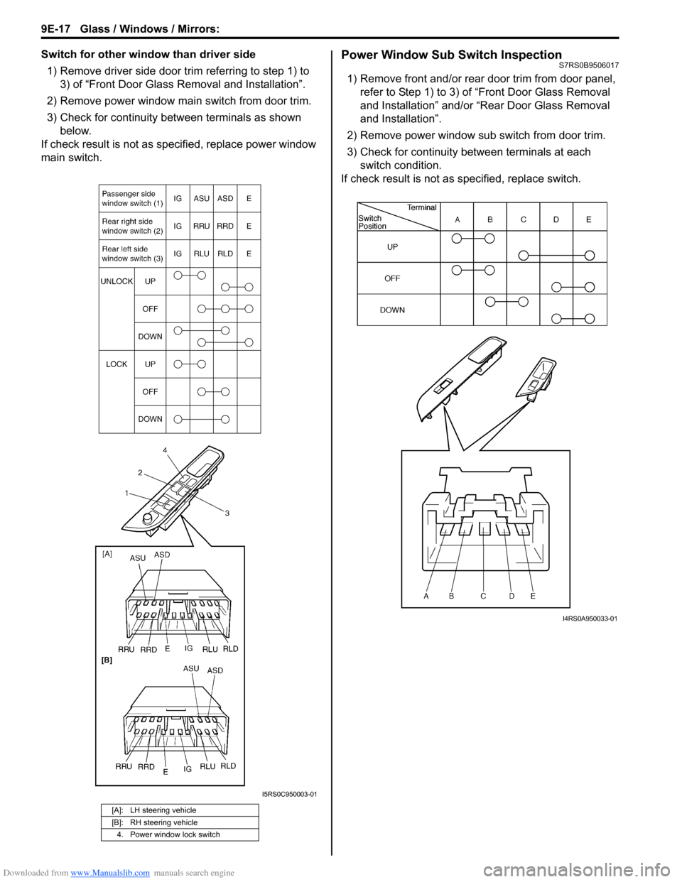
Switch for other window than driver side1) Remove driver side door trim referring to step 1) to 3) of “Front Door Glass Removal and Installation”.
2) Remove power window main switch from door trim.
3) Check for continuity between terminals as shown below.
If check result is not as sp ecified, replace power window
main switch.Power Window Sub Switch InspectionS7RS0B9506017
1) Remove front and/or rear door trim from door panel, refer to Step 1) to 3) of “Front Door Glass Removal
and Installation” and/or “Rear Door Glass Removal
and Installation”.
2) Remove power window sub switch from door trim.
3) Check for continuity between terminals at each switch condition.
If check result is not as specified, replace switch.
[A]: LH steering vehicle
[B]: RH steering vehicle
4. Power window lock switch
I5RS0C950003-01
I4RS0A950033-01
Page 1346 of 1496
Downloaded from www.Manualslib.com manuals search engine 9E-19 Glass / Windows / Mirrors:
Power Door Mirror Actuator InspectionS7RS0B9506021
1) Remove front door trim referring to step 1) to 3) of “Front Door Glass Removal and Installation”.
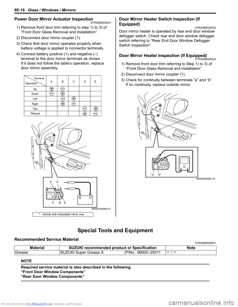
2) Disconnect door mirror coupler (1).
3) Check that door mirror operates properly when battery voltage is applied to connector terminals.
4) Connect battery positive (+) and negative (–) terminal to the door mirror terminals as shown.
If it does not follow the table’s operation, replace
door mirror assembly.
Door Mirror Heater Switch Inspection (If
Equipped)
S7RS0B9506022
Door mirror heater is operated by rear end door window
defogger switch. Check rear end door window defogger
switch referring to “Rear End Door Window Defogger
Switch Inspection”.
Door Mirror Heater Inspection (If Equipped)S7RS0B9506023
1) Remove front door trim refe rring to Step 1) to 3) of
“Front Door Glass Removal and Installation”.
2) Disconnect door mirror coupler (1).
3) Check for continuity between terminals “a” and “b”. If no continuity, replace outside mirror.
Special Tools and Equipment
Recommended Service MaterialS7RS0B9508001
NOTE
Required service material is also described in the following.
“Front Door Window Components”
“Rear Door Window Components”
*: Vehicle with retractable mirror only
Operation
Terminal
Up
Down
Left
RightCBA
1
C B
A
*Set
*Retract
DE
DE
I5RS0C950005-01
1
“a” “b”
I5RS0D950001-01
Material
SUZUKI recommended product or Specification Note
Grease SUZUKI Super Grease A P/No.: 99000–25011) / )
Page 1349 of 1496
Downloaded from www.Manualslib.com manuals search engine Security and Locks: 9F-3
Diagnostic Information and Procedures
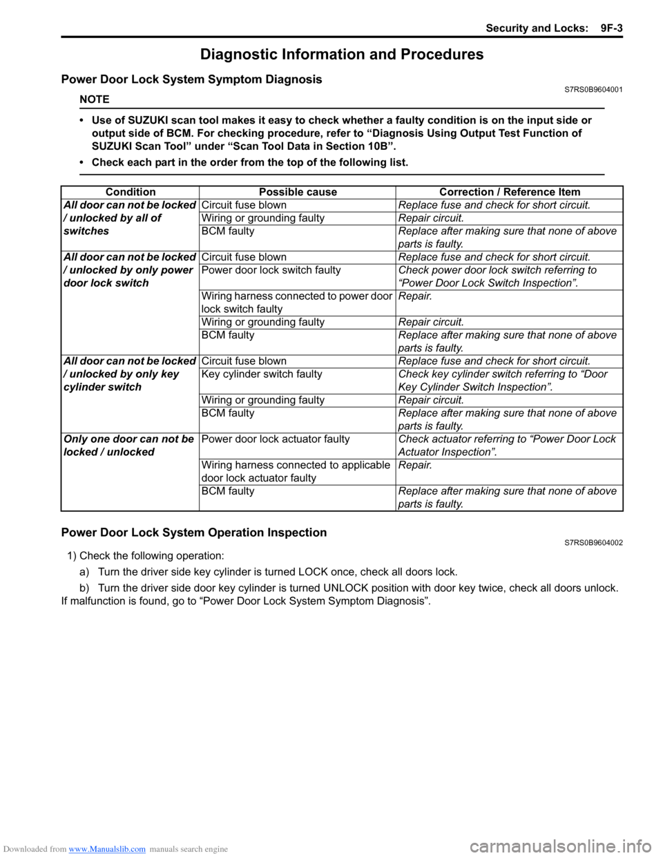
Power Door Lock System Symptom DiagnosisS7RS0B9604001
NOTE
• Use of SUZUKI scan tool makes it easy to check whether a faulty condition is on the input side or
output side of BCM. For checking procedure, re fer to “Diagnosis Using Output Test Function of
SUZUKI Scan Tool” under “Scan Tool Data in Section 10B”.
• Check each part in the order from the top of the following list.
Power Door Lock System Operation InspectionS7RS0B9604002
1) Check the following operation:
a) Turn the driver side key cylinder is turned LOCK once, check all doors lock.
b) Turn the driver side door key cylinder is turned UNLOC K position with door key twice, check all doors unlock.
If malfunction is found, go to “Power Door Lock System Symptom Diagnosis”.
Condition Possible cause Correction / Reference Item
All door can not be locked
/ unlocked by all of
switches Circuit fuse blown
Replace fuse and check for short circuit.
Wiring or grounding faulty Repair circuit.
BCM faulty Replace after making sure that none of above
parts is faulty.
All door can not be locked
/ unlocked by only power
door lock switch Circuit fuse blown
Replace fuse and check for short circuit.
Power door lock switch faulty Check power door lock switch referring to
“Power Door Lock Switch Inspection”.
Wiring harness connected to power door
lock switch faulty Repair.
Wiring or grounding faulty Repair circuit.
BCM faulty Replace after making sure that none of above
parts is faulty.
All door can not be locked
/ unlocked by only key
cylinder switch Circuit fuse blown
Replace fuse and check for short circuit.
Key cylinder switch faulty Check key cylinder switch referring to “Door
Key Cylinder Switch Inspection”.
Wiring or grounding faulty Repair circuit.
BCM faulty Replace after making sure that none of above
parts is faulty.
Only one door can not be
locked / unlocked Power door lock actuator faulty
Check actuator referring to “Power Door Lock
Actuator Inspection”.
Wiring harness connected to applicable
door lock actuator faulty Repair.
BCM faulty Replace after making sure that none of above
parts is faulty.
Page 1350 of 1496
Downloaded from www.Manualslib.com manuals search engine 9F-4 Security and Locks:
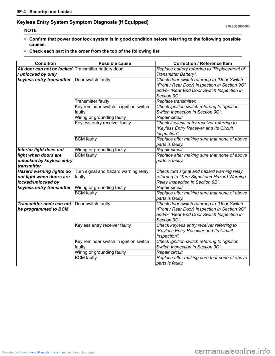
Keyless Entry System Symptom Diagnosis (If Equipped)S7RS0B9604003
NOTE
• Confirm that power door lock system is in good condition before referring to the following possible causes.
• Check each part in the order from the top of the following list.
Condition Possible cause Correction / Reference Item
All door can not be locked
/ unlocked by only
keyless entry transmitter Transmitter battery dead
Replace battery referring to “Replacement of
Transmitter Battery”.
Door switch faulty Check door switch referring to “Door Switch
(Front / Rear Door) Inspection in Section 9C”
and/or “Rear End Door Switch Inspection in
Section 9C”.
Transmitter faulty Replace transmitter.
Key reminder switch in ignition switch
faulty Check ignition switch referring to “Ignition
Switch Inspection in Section 9C”.
Wiring or grounding faulty Repair circuit.
Keyless entry receiver faulty Check keyless entry receiver referring to
“Keyless Entry Receiver and Its Circuit
Inspection”.
BCM faulty Replace after making sure that none of above
parts is faulty.
Interior light does not
light when doors are
unlocked by keyless entry
transmitter Wiring or grounding faulty
Repair circuit.
BCM faulty Replace after making sure that none of above
parts is faulty.
Hazard warning lights do
not light when doors are
locked/unlocked by
keyless entry transmitter Turn signal and hazard warning relay
faulty
Check turn signal and hazard warning relay
referring to “Turn Signal and Hazard Warning
Relay Inspection in Section 9B”.
Wiring or grounding faulty Repair circuit.
BCM faulty Replace after making sure that none of above
parts is faulty.
Transmitter code can not
be programmed to BCM Door switch faulty
Check door switch referring to “Door Switch
(Front / Rear Door) Inspection in Section 9C”
and/or “Rear End Door Switch Inspection in
Section 9C”.
Keyless entry receiver faulty Check keyless entry receiver referring to
“Keyless Entry Receiver and Its Circuit
Inspection”.
Key reminder switch in ignition switch
faulty Check ignition switch referring to “Ignition
Switch Inspection in Section 9C”.
Wiring or grounding faulty Repair circuit.
BCM faulty Replace after making sure that none of above
parts is faulty.
Page 1351 of 1496
Downloaded from www.Manualslib.com manuals search engine Security and Locks: 9F-5
Keyless Entry System Operation InspectionS7RS0B9604004
NOTE
When performing the this inspection, make
sure to have any of the door once opened/
closed after the ignition key has been
removed from the ignition key cylinder.
1) Confirm that power door lock system operates normally, refer to “Power Door Lock System
Operation Inspection”.
2) All doors are closed and unlocked.
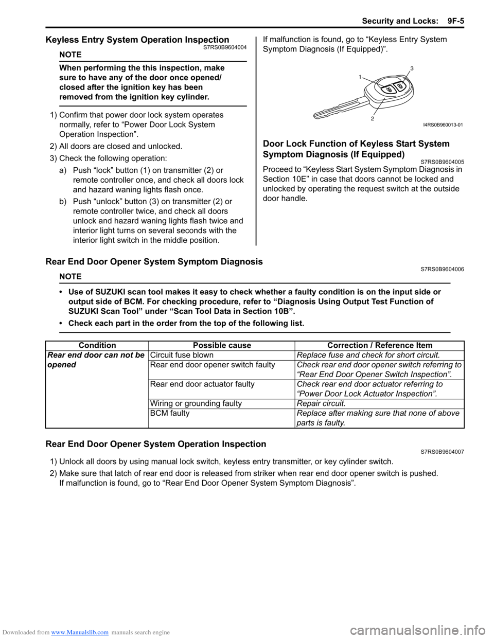
3) Check the following operation: a) Push “lock” button (1 ) on transmitter (2) or
remote controller once, and check all doors lock
and hazard waning lights flash once.
b) Push “unlock” button (3) on transmitter (2) or remote controller twice, and check all doors
unlock and hazard waning lights flash twice and
interior light turns on several seconds with the
interior light switch in the middle position. If malfunction is found, go to “Keyless Entry System
Symptom Diagnosis (If Equipped)”.
Door Lock Function of Keyless Start System
Symptom Diagnosis (If Equipped)
S7RS0B9604005
Proceed to “Keyless Start System Symptom Diagnosis in
Section 10E” in case that doors cannot be locked and
unlocked by operating the request switch at the outside
door handle.
Rear End Door Opener System Symptom DiagnosisS7RS0B9604006
NOTE
• Use of SUZUKI scan tool makes it easy to check wh
ether a faulty condition is on the input side or
output side of BCM. For checking procedure, re fer to “Diagnosis Using Output Test Function of
SUZUKI Scan Tool” under “Scan Tool Data in Section 10B”.
• Check each part in the order from the top of the following list.
Rear End Door Opener System Operation InspectionS7RS0B9604007
1) Unlock all doors by using manu al lock switch, keyless entry transmitter, or key cylinder switch.
2) Make sure that latch of rear end door is released from striker when rear end door opener switch is pushed. If malfunction is found, go to “Rear End Door Opener System Symptom Diagnosis”.
1
3
2I4RS0B960013-01
ConditionPossible cause Correction / Reference Item
Rear end door can not be
opened Circuit fuse blown
Replace fuse and check for short circuit.
Rear end door opener switch faulty Check rear end door opener switch referring to
“Rear End Door Opener Switch Inspection”.
Rear end door actuator faulty Check rear end door actuator referring to
“Power Door Lock Actuator Inspection”.
Wiring or grounding faulty Repair circuit.
BCM faulty Replace after making sure that none of above
parts is faulty.
Page 1353 of 1496
Downloaded from www.Manualslib.com manuals search engine Security and Locks: 9F-7
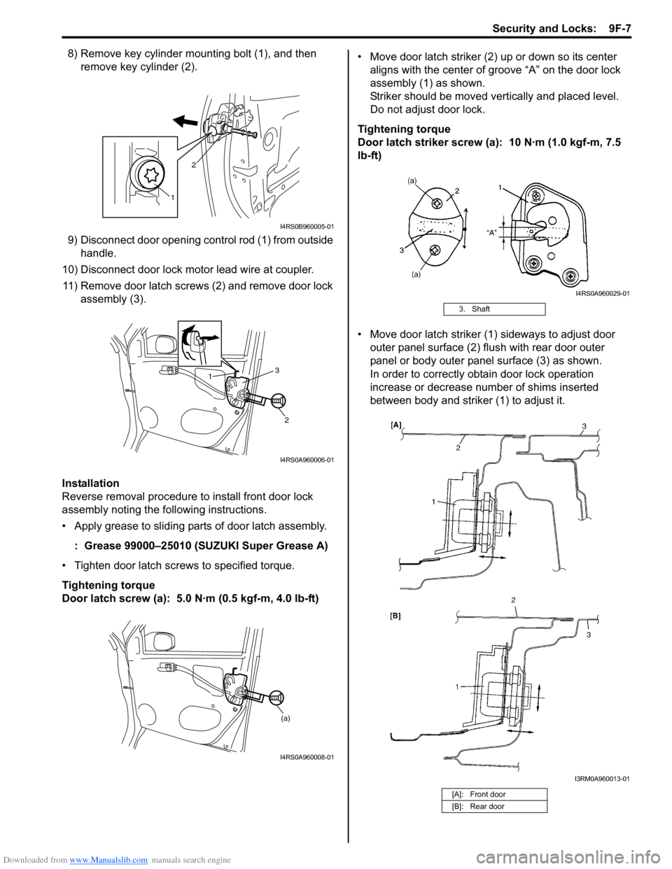
8) Remove key cylinder mounting bolt (1), and then remove key cylinder (2).
9) Disconnect door opening control rod (1) from outside handle.
10) Disconnect door lock motor lead wire at coupler. 11) Remove door latch screws (2) and remove door lock assembly (3).
Installation
Reverse removal procedure to install front door lock
assembly noting the following instructions.
• Apply grease to sliding parts of door latch assembly.
: Grease 99000–25010 (SUZUKI Super Grease A)
• Tighten door latch screws to specified torque.
Tightening torque
Door latch screw (a): 5.0 N·m (0.5 kgf-m, 4.0 lb-ft) • Move door latch striker (2) up or down so its center
aligns with the center of groove “A” on the door lock
assembly (1) as shown.
Striker should be moved vertically and placed level.
Do not adjust door lock.
Tightening torque
Door latch striker screw (a): 10 N·m (1.0 kgf-m, 7.5
lb-ft)
• Move door latch striker (1) sideways to adjust door outer panel surface (2) flush with rear door outer
panel or body outer panel surface (3) as shown.
In order to correctly obtain door lock operation
increase or decrease number of shims inserted
between body and striker (1) to adjust it.
1 2
I4RS0B960005-01
1
2
3
I4RS0A960006-01
(a)
I4RS0A960008-01
3. Shaft
[A]: Front door
[B]: Rear door
I4RS0A960029-01
I3RM0A960013-01
Page 1355 of 1496

Downloaded from www.Manualslib.com manuals search engine Security and Locks: 9F-9
Power Door Lock Actuator InspectionS7RS0B9606006
1) Remove door trim from door panel.For front door, refer to Step 1) to 3) of “Front Door
Glass Removal and Installation in Section 9E”.
For rear door, refer to Step 1) to 3) of “Rear Door
Glass Removal and Installation in Section 9E”.
For rear end door, refer to Step 1) of “Rear End Door
Assembly Removal and Installation in Section 9J”.
2) Disconnect power door lock actuator coupler.
3) Connect battery positive (+) and negative (–) terminals to the door lock actuator terminals (a, b, c,
d) as shown in figure.
If it does not operate as specified in the following
table, replace door lock assembly.
[A]: Front door
[B]: Rear door
[C]: Rear end door
Unlock Lock
Lock Unlock
Right side switch terminals
Left side switch terminals ac db
ab cd
[A]
Unlock Lock
Lock Unlock
Right side switch terminals
Left side switch terminals
a
c
d b
ab cd
[B]
ab
Lock
Unlock
a
b
[C]
I4RS0A960011-02
Page 1356 of 1496
Downloaded from www.Manualslib.com manuals search engine 9F-10 Security and Locks:
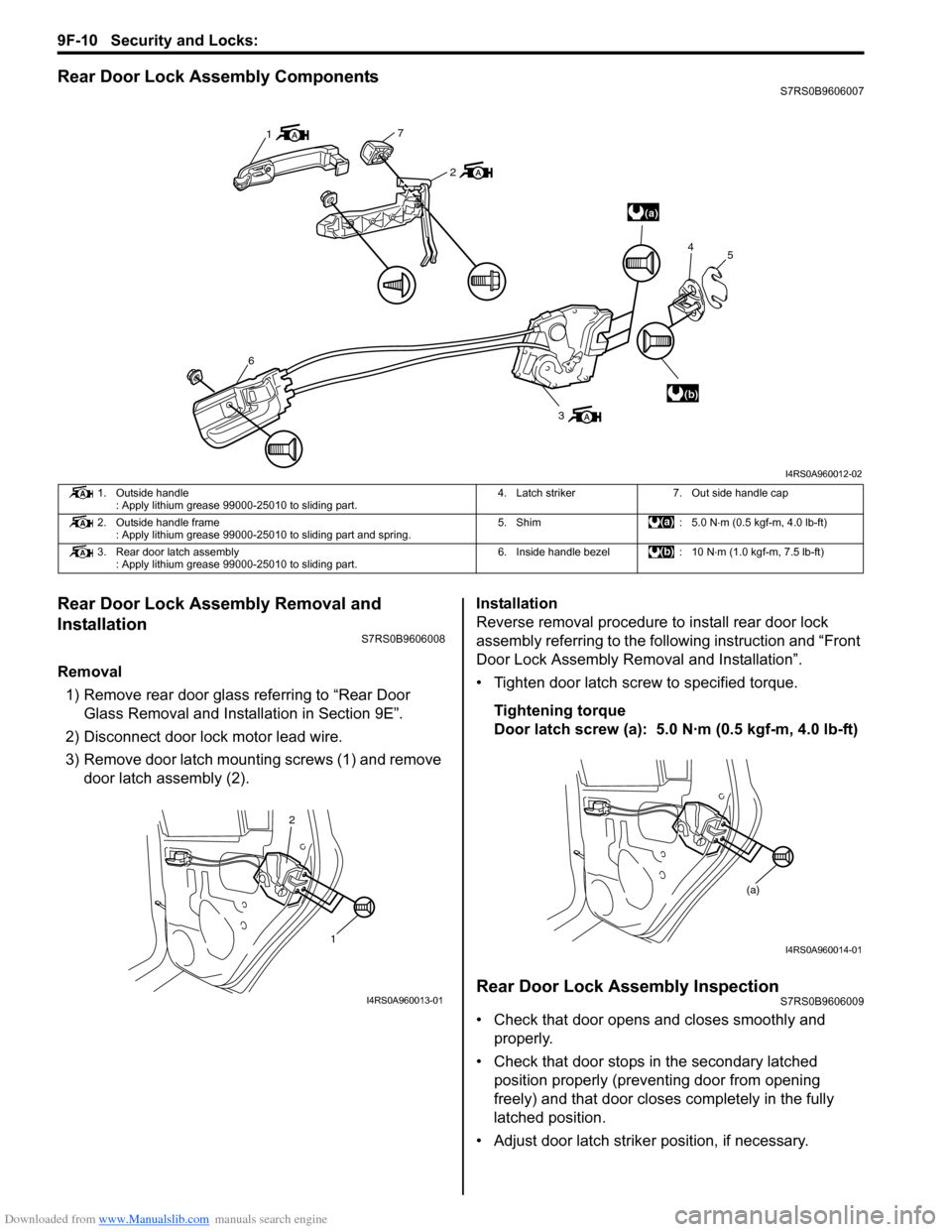
Rear Door Lock Assembly ComponentsS7RS0B9606007
Rear Door Lock Assembly Removal and
Installation
S7RS0B9606008
Removal1) Remove rear door glass referring to “Rear Door Glass Removal and Installation in Section 9E”.
2) Disconnect door lock motor lead wire.
3) Remove door latch mounting screws (1) and remove door latch assembly (2). Installation
Reverse removal procedure to install rear door lock
assembly referring to the following instruction and “Front
Door Lock Assembly Re
moval and Installation”.
• Tighten door latch screw to specified torque.
Tightening torque
Door latch screw (a): 5.0 N·m (0.5 kgf-m, 4.0 lb-ft)
Rear Door Lock Assembly InspectionS7RS0B9606009
• Check that door opens and closes smoothly and properly.
• Check that door stops in the secondary latched position properly (preventing door from opening
freely) and that door closes completely in the fully
latched position.
• Adjust door latch strike r position, if necessary.
(a)
(b)
1
7
2
6
3 4
5
I4RS0A960012-02
1. Outside handle
: Apply lithium grease 99000-25010 to sliding part. 4. Latch striker 7. Out side handle cap
2. Outside handle frame : Apply lithium grease 99000-25010 to sliding part and spring. 5. Shim : 5.0 N
⋅m (0.5 kgf-m, 4.0 lb-ft)
3. Rear door latch assembly : Apply lithium grease 99000-25010 to sliding part. 6. Inside handle bezel : 10 N
⋅m (1.0 kgf-m, 7.5 lb-ft)
1
2
I4RS0A960013-01
(a)
I4RS0A960014-01
Page 1358 of 1496
Downloaded from www.Manualslib.com manuals search engine 9F-12 Security and Locks:
Installation
Reverse removal procedure to install rear end door lock
assembly noting the following instruction.
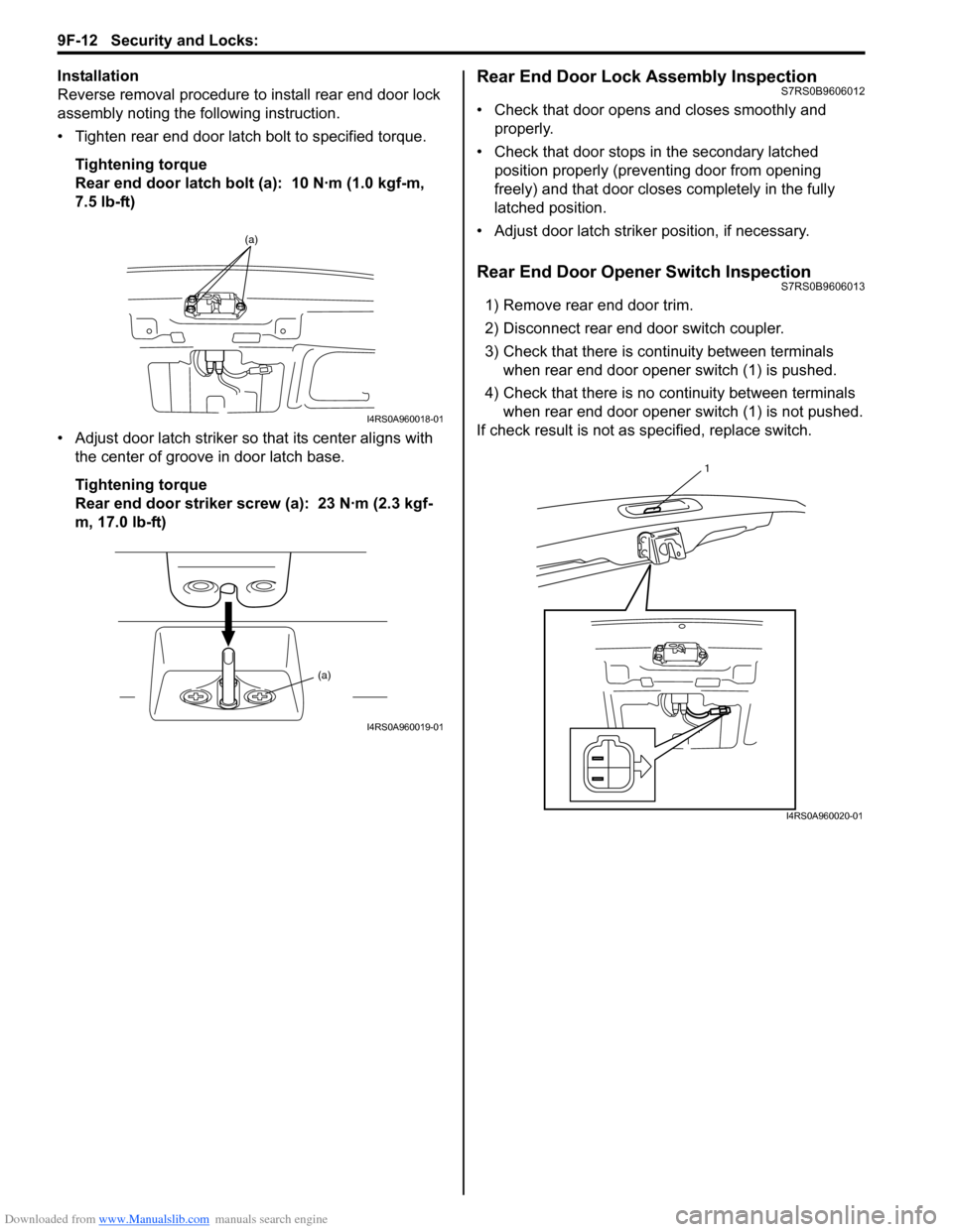
• Tighten rear end door latch bolt to specified torque.
Tightening torque
Rear end door latch bolt (a): 10 N·m (1.0 kgf-m,
7.5 lb-ft)
• Adjust door latch striker so that its center aligns with the center of groove in door latch base.
Tightening torque
Rear end door striker screw (a): 23 N·m (2.3 kgf-
m, 17.0 lb-ft)Rear End Door Lock Assembly InspectionS7RS0B9606012
• Check that door opens and closes smoothly and properly.
• Check that door stops in the secondary latched position properly (preventing door from opening
freely) and that door closes completely in the fully
latched position.
• Adjust door latch strike r position, if necessary.
Rear End Door Opener Switch InspectionS7RS0B9606013
1) Remove rear end door trim.
2) Disconnect rear end door switch coupler.
3) Check that there is continuity between terminals
when rear end door opener switch (1) is pushed.
4) Check that there is no continuity between terminals when rear end door opener switch (1) is not pushed.
If check result is not as specified, replace switch.
(a)
I4RS0A960018-01
(a)
I4RS0A960019-01
1
I4RS0A960020-01
Page 1359 of 1496
Downloaded from www.Manualslib.com manuals search engine Security and Locks: 9F-13
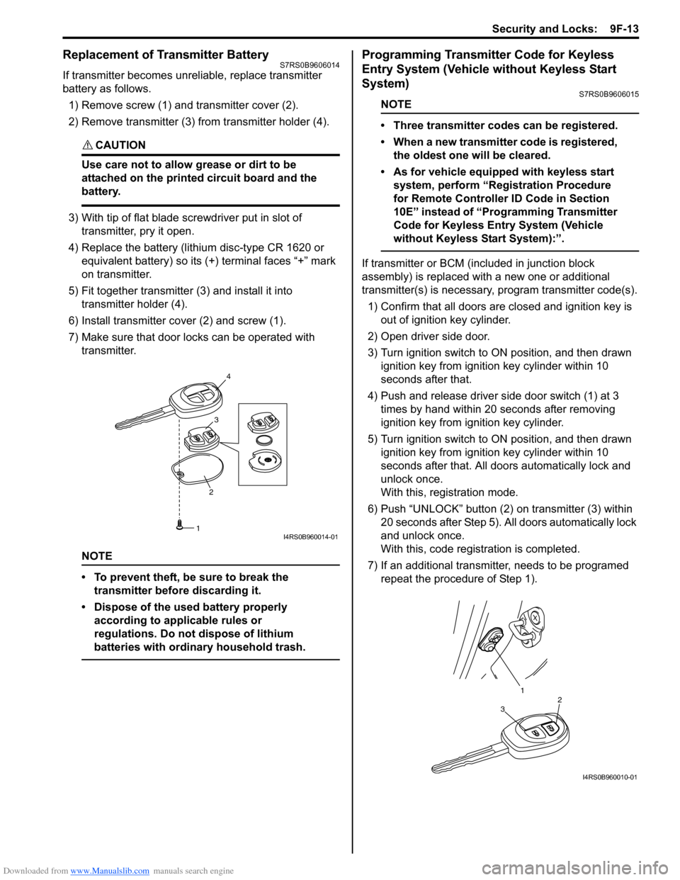
Replacement of Transmitter Battery S7RS0B9606014
If transmitter becomes unreliable, replace transmitter
battery as follows.
1) Remove screw (1) and transmitter cover (2).
2) Remove transmitter (3) from transmitter holder (4).
CAUTION!
Use care not to allow grease or dirt to be
attached on the printed circuit board and the
battery.
3) With tip of flat blade screwdriver put in slot of transmitter, pry it open.
4) Replace the battery (lithium disc-type CR 1620 or equivalent battery) so its (+) terminal faces “+” mark
on transmitter.
5) Fit together transmitter (3) and install it into
transmitter holder (4).
6) Install transmitter co ver (2) and screw (1).
7) Make sure that door locks can be operated with transmitter.
NOTE
• To prevent theft, be sure to break the transmitter before discarding it.
• Dispose of the used battery properly according to applicable rules or
regulations. Do not dispose of lithium
batteries with ordinary household trash.
Programming Transmitter Code for Keyless
Entry System (Vehicle without Keyless Start
System)
S7RS0B9606015
NOTE
• Three transmitter codes can be registered.
• When a new transmitter code is registered, the oldest one will be cleared.
• As for vehicle equipped with keyless start system, perform “Registration Procedure
for Remote Controller ID Code in Section
10E” instead of “Programming Transmitter
Code for Keyless Entry System (Vehicle
without Keyless Start System):”.
If transmitter or BCM (included in junction block
assembly) is replaced with a new one or additional
transmitter(s) is necessary, program transmitter code(s).
1) Confirm that all doors are closed and ignition key is
out of ignition key cylinder.
2) Open driver side door.
3) Turn ignition switch to ON position, and then drawn ignition key from igniti on key cylinder within 10
seconds after that.
4) Push and release driver side door switch (1) at 3 times by hand within 20 seconds after removing
ignition key from ig nition key cylinder.
5) Turn ignition switch to ON position, and then drawn ignition key from igniti on key cylinder within 10
seconds after that. All d oors automatically lock and
unlock once.
With this, registration mode.
6) Push “UNLOCK” button (2) on transmitter (3) within
20 seconds after Step 5). All doors automatically lock
and unlock once.
With this, code registration is completed.
7) If an additional transmitter, needs to be programed repeat the procedure of Step 1).
23
4
1I4RS0B960014-01
1
32
I4RS0B960010-01