low SUZUKI SWIFT 2007 2.G Service Workshop Manual
[x] Cancel search | Manufacturer: SUZUKI, Model Year: 2007, Model line: SWIFT, Model: SUZUKI SWIFT 2007 2.GPages: 1496, PDF Size: 34.44 MB
Page 1360 of 1496
Downloaded from www.Manualslib.com manuals search engine 9F-14 Security and Locks:
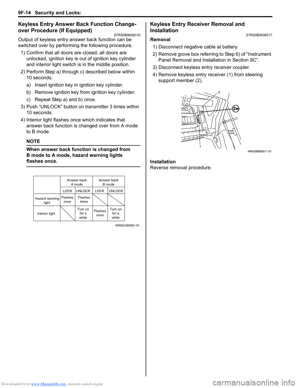
Keyless Entry Answer Back Function Change-
over Procedure (If Equipped)
S7RS0B9606016
Output of keyless entry answer back function can be
switched over by performing the following procedure.
1) Confirm that all doors are closed, all doors are unlocked, ignition key is out of ignition key cylinder
and interior light switch is in the middle position.
2) Perform Step a) through c) described below within 10 seconds.
a) Insert ignition key in ignition key cylinder.
b) Remove ignition key from ignition key cylinder.
c) Repeat Step a) and b) once.
3) Push “UNLOCK” button on transmitter 3 times within 10 seconds.
4) Interior light flashes once which indicates that answer back function is changed over from A mode
to B mode.
NOTE
When answer back function is changed from
B mode to A mode, hazard warning lights
flashes once.
Keyless Entry Receiver Removal and
Installation
S7RS0B9606017
Removal
1) Disconnect negative cable at battery.
2) Remove grove box referring to Step 6) of “Instrument Panel Removal and Installation in Section 9C”.
3) Disconnect keyless entry receiver coupler.
4) Remove keyless entry receiver (1) from steering support member (2).
Installation
Reverse removal procedure.
Hazard warning light
LOCK LOCK
UNLOCK UNLOCK
Interior lightFlashes
once Flashes
twice
Flashesonce
Turn on
for a
while Turn on
for a
while
Answer back
A mode Answer back
B mode
I5RS0C960001-01
1 2I4RS0B960011-01
Page 1361 of 1496
Downloaded from www.Manualslib.com manuals search engine Security and Locks: 9F-15
Keyless Entry Receiver and Its Circuit InspectionS7RS0B9606018
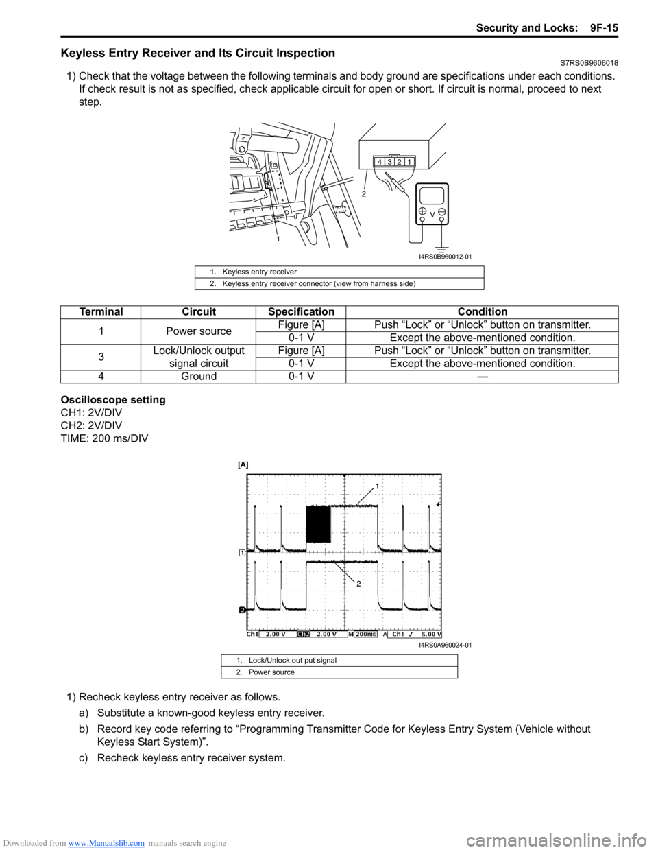
1) Check that the voltage between the following terminals and body ground are specifications under each conditions.
If check result is not as specified, ch eck applicable circuit for open or short. If circuit is normal, proceed to next
step.
Oscilloscope setting
CH1: 2V/DIV
CH2: 2V/DIV
TIME: 200 ms/DIV 1) Recheck keyless entry receiver as follows.
a) Substitute a known-good keyless entry receiver.
b) Record key code referring to “Programming Transmit ter Code for Keyless Entry System (Vehicle without
Keyless Start System)”.
c) Recheck keyless entry receiver system.
1. Keyless entry receiver
2. Keyless entry receiver connector (view from harness side)
1234
V
1 2
I4RS0B960012-01
Terminal
Circuit Specification Condition
1 Power source Figure [A] Push “Lock” or “Unlock” button on transmitter.
0-1 V Except the above-mentioned condition.
3 Lock/Unlock output
signal circuit Figure [A] Push “Lock” or “Unlock” button on transmitter.
0-1 V Except the above-mentioned condition.
4G ro un d0 -1 V —
1. Lock/Unlock out put signal
2. Power source
I4RS0A960024-01
Page 1362 of 1496
Downloaded from www.Manualslib.com manuals search engine 9F-16 Security and Locks:
Specifications
Tightening Torque SpecificationsS7RS0B9607001
NOTE
The specified tightening torque is also described in the following.
“Front Door Lock Assembly Components”
“Rear Door Lock Assembly Components”
“Rear End Door Lock Assembly Components”
Reference:
For the tightening torque of fastener not specified in this section, refer to “Fasteners Information in Section 0A”.
Special Tools and Equipment
Recommended Service MaterialS7RS0B9608001
NOTE
Required service material is also described in the following.
“Front Door Lock Assembly Components”
“Rear Door Lock Assembly Components”
Fastening part Tightening torque
Note
N ⋅mkgf-mlb-ft
Door latch screw 5.0 0.5 4.0 ) / )
Door latch striker screw 10 1.0 7.5 )
Rear end door latch bolt 10 1.0 7.5 )
Rear end door striker screw 23 2.3 17.0 )
MaterialSUZUKI recommended product or Specification Note
Grease SUZUKI Super Grease A P/No.: 99000–25010)
Page 1366 of 1496
Downloaded from www.Manualslib.com manuals search engine 9G-4 Seats:
Rear Seat Removal and InstallationS7RS0B9706004
Removal1) Fold rear seat back forward.
2) Remove seat mounting bolts and nuts to remove seat assembly.
3) Disassemble and repair seat as necessary.
Installation
Reverse removal procedure to install rear seat.
• Tighten seat back striker mounting bolts according to “Rear Seat Components”.
• Torque to specifications in “Rear Seat Components”.
• When installing seat cushion, align seat cushion hook with center hinge bracket.
Specifications
Tightening Torque SpecificationsS7RS0B9707001
NOTE
The specified tightening torque is also described in the following.
“Front Seat Components”
“Rear Seat Components”
Reference:
For the tightening torque of fastener not specified in this section, refer to “Fasteners Information in Section 0A”.
Special Tools and Equipment
Recommended Service MaterialS7RS0B9708001
NOTE
Required service material is also described in the following.
“Front Seat Components”
Material SUZUKI recommended product or Specification Note
Thread lock cement Thread Lock Cement Super 1303B P/No.: 99000–32030 )
Thread Lock Cement 1305 P/No.: 99000–32100 )
Page 1367 of 1496
Downloaded from www.Manualslib.com manuals search engine Interior Trim: 9H-1
Body, Cab and Accessories
Interior Trim
Repair Instructions
Floor Carpet Removal and InstallationS7RS0B9806001
WARNING!
Refer to “Air Bag Warning in Section 00”
before starting service work.
Removal1) Remove front seats and rear seats referring to “Front Seat Removal and Installa tion in Section 9G” and
“Rear Seat Removal and Installation in Section 9G”.
2) Remove seat belt lower anchor bolt.
3) Remove dash side trims, fr ont side sill scuffs, center
pillar inner lower trims, qu arter inner front trims and
rear side sill scuffs.
4) Remove console box.
5) Remove floor carpet.
Installation
Reverse removal sequence to install floor carpet, noting
the following instruction.
• For tightening torque of rear seat mounting bolt, refer to “Rear Seat Components in Section 9G”.
• For tightening torque of front seat mounting bolt, refer to “Front Seat Components in Section 9G”.
Head Lining Removal and InstallationS7RS0B9806002
WARNING!
Refer to “Air Bag Warning in Section 00”
before starting service work.
Removal
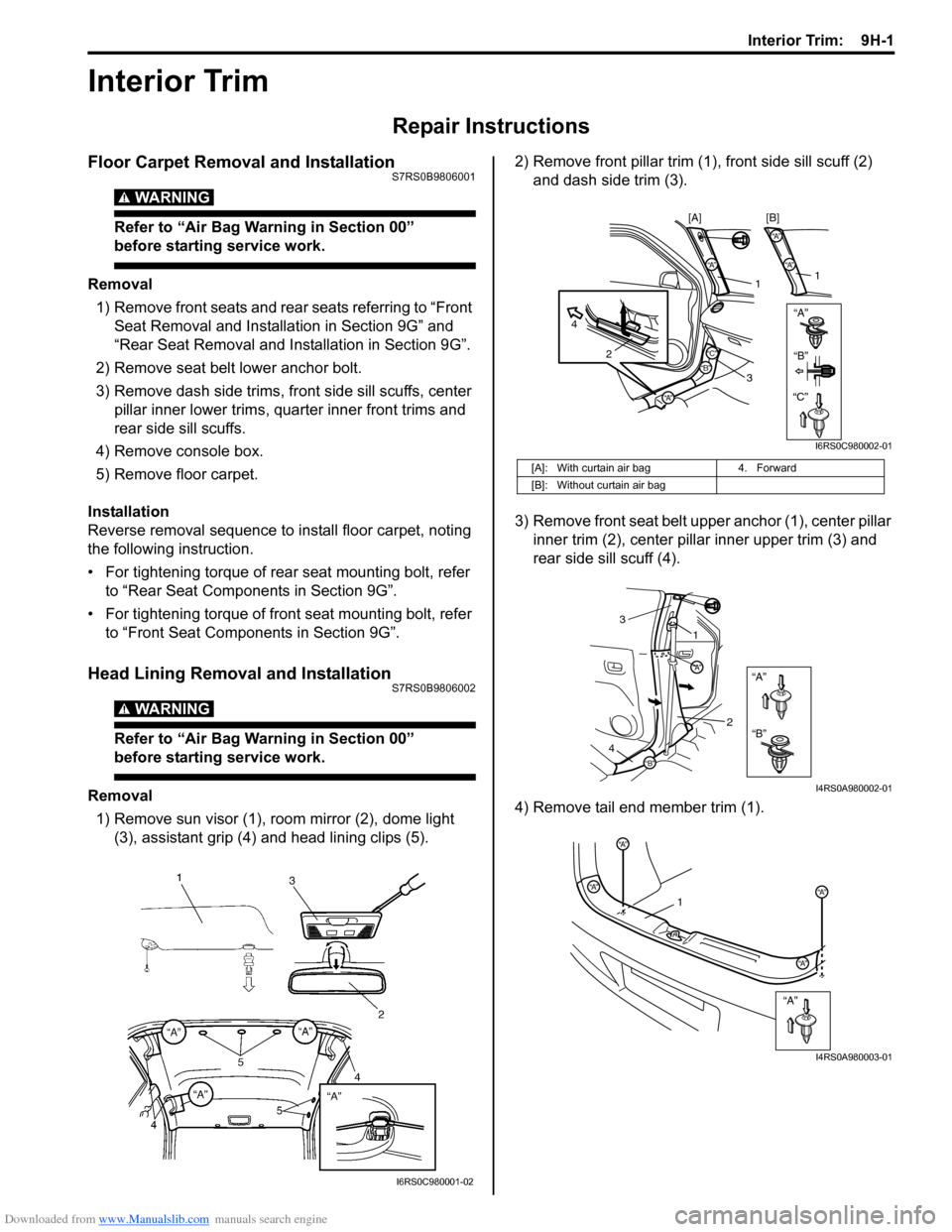
1) Remove sun visor (1), room mirror (2), dome light (3), assistant grip (4) and head lining clips (5). 2) Remove front pillar trim (1
), front side sill scuff (2)
and dash side trim (3).
3) Remove front seat belt u pper anchor (1), center pillar
inner trim (2), center pillar inner upper trim (3) and
rear side sill scuff (4).
4) Remove tail end member trim (1).
I6RS0C980001-02
[A]: With curtain air bag 4. Forward
[B]: Without curtain air bag
“A”“A”
“A”
2
4
1
3
“A”
“A”
1
[B]
[A]
“B”“B”
“C”“C”
I6RS0C980002-01
“A”
“B”
“A”
“B”
1
3
2
4
I4RS0A980002-01
“A”
“A”
“A”
“A”“A”1
I4RS0A980003-01
Page 1368 of 1496

Downloaded from www.Manualslib.com manuals search engine 9H-2 Interior Trim:
5) Remove quarter inner rear upper trim (1), quarter inner rear lower trim (2), quarter inner front trim (3)
and quarter inner upper trim (4).
6) Remove head lining. Installation
Reverse removal procedure noting the following.
• Apply adhesive (1) to head lining (2) as shown in the
figure, and then install head lining (2).
• Tighten sun visor scre w to specified torque.
Tightening torque
Sun visor screw (a): 4 N·m (0.4 kgf-m, 3.0 lb-ft)
Console Box ComponentsS7RS0B9806003
AA
A
A
A
A
DD
B
BB
CC
D
C
A
B
1
2
3
4
A
I7RS0A980001-01
1 1
2
I6RS0C980004-01
I4RS0A980007-01
“B”
“A”
“A”
“A”
“A”“A”
“A”
“A”“A”
“A”
“B”
“B”
1 2
3
4
“C”
“C”
“C”
I4RS0A980008-01
1. Front console box
2. Rear console box 3. Front console box garnish4. Console side cover
Page 1370 of 1496
Downloaded from www.Manualslib.com manuals search engine 9J-1 Hood / Fenders / Doors:
Body, Cab and Accessories
Hood / Fenders / Doors
Repair Instructions
Hood Removal and InstallationS7RS0B9A06001
Removal
CAUTION!
Place cloth to prevent body from any
damage.
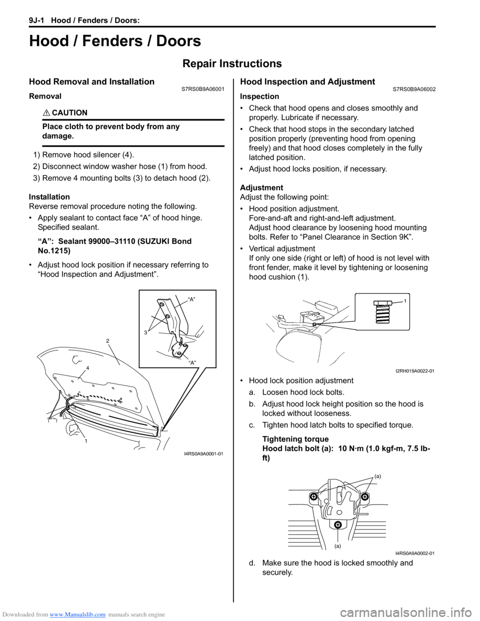
1) Remove hood silencer (4).
2) Disconnect window washer hose (1) from hood.
3) Remove 4 mounting bolts (3) to detach hood (2).
Installation
Reverse removal procedure noting the following.
• Apply sealant to contact face “A” of hood hinge. Specified sealant.
“A”: Sealant 99000–31110 (SUZUKI Bond
No.1215)
• Adjust hood lock position if necessary referring to “Hood Inspection and Adjustment”.
Hood Inspection and AdjustmentS7RS0B9A06002
Inspection
• Check that hood opens and closes smoothly and properly. Lubricate if necessary.
• Check that hood stops in the secondary latched position properly (preventing hood from opening
freely) and that hood closes completely in the fully
latched position.
• Adjust hood locks position, if necessary.
Adjustment
Adjust the following point:
• Hood position adjustment. Fore-and-aft and right-and-left adjustment.
Adjust hood clearance by loosening hood mounting
bolts. Refer to “Panel Clearance in Section 9K”.
• Vertical adjustment If only one side (right or left) of hood is not level with
front fender, make it level by tightening or loosening
hood cushion (1).
• Hood lock position adjustment a. Loosen hood lock bolts.
b. Adjust hood lock height position so the hood is locked without looseness.
c. Tighten hood latch bolts to specified torque.
Tightening torque
Hood latch bolt (a): 10 N·m (1.0 kgf-m, 7.5 lb-
ft)
d. Make sure the hood is locked smoothly and securely.
“A”
“A”
3
2
4
1
I4RS0A9A0001-01
I2RH019A0022-01
(a)
(a)I4RS0A9A0002-01
Page 1371 of 1496
Downloaded from www.Manualslib.com manuals search engine Hood / Fenders / Doors: 9J-2
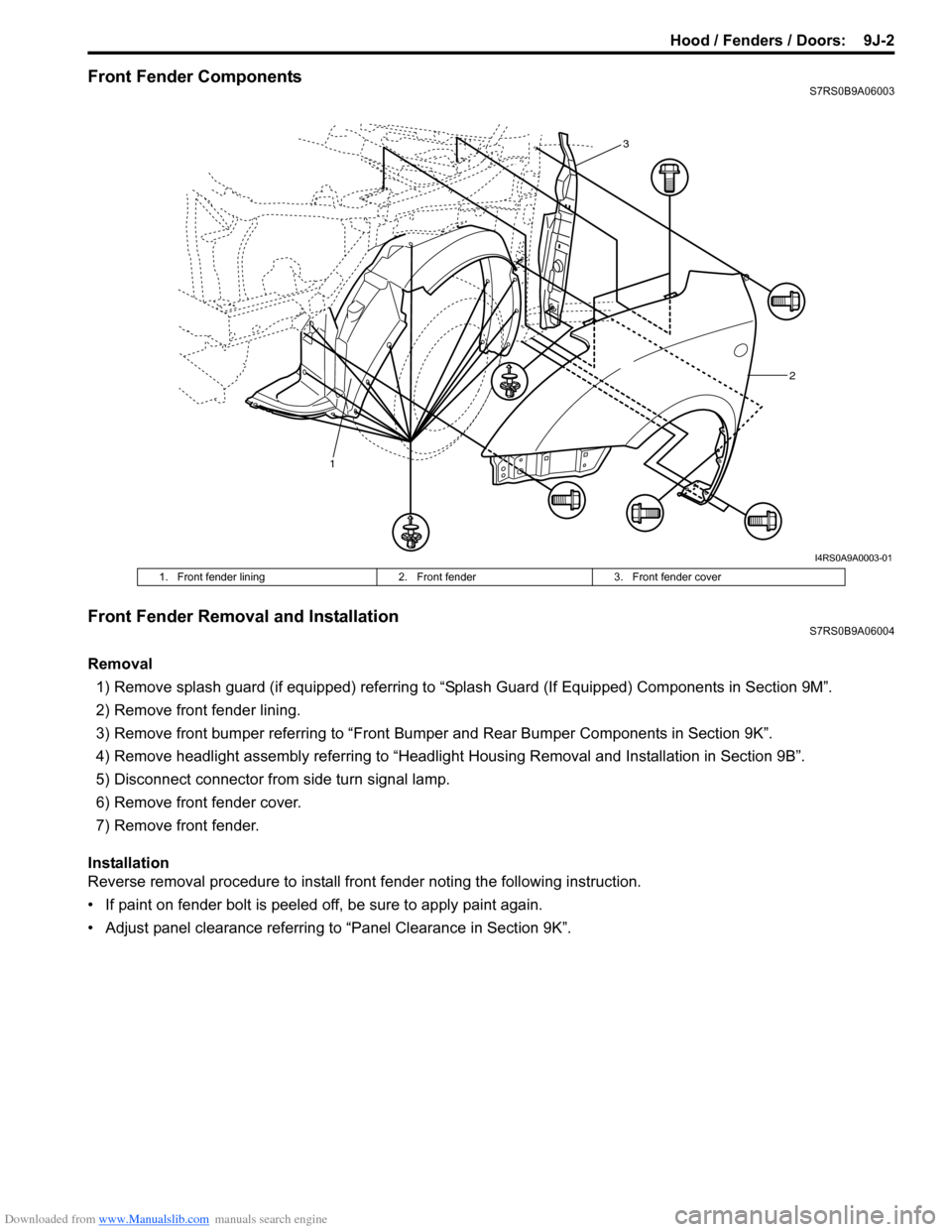
Front Fender ComponentsS7RS0B9A06003
Front Fender Removal and InstallationS7RS0B9A06004
Removal1) Remove splash guard (if equipped) referring to “Splash Guard (If Equipped) Components in Section 9M”.
2) Remove front fender lining.
3) Remove front bumper referring to “Front Bumper and Rear Bumper Components in Section 9K”.
4) Remove headlight assembly referring to “Headlig ht Housing Removal and Installation in Section 9B”.
5) Disconnect connector from side turn signal lamp.
6) Remove front fender cover.
7) Remove front fender.
Installation
Reverse removal procedure to install fron t fender noting the following instruction.
• If paint on fender bolt is peeled off, be sure to apply paint again.
• Adjust panel clearance referring to “Panel Clearance in Section 9K”.
1 2
3
I4RS0A9A0003-01
1. Front fender lining
2. Front fender3. Front fender cover
Page 1373 of 1496
Downloaded from www.Manualslib.com manuals search engine Hood / Fenders / Doors: 9J-4
Installation
Reverse removal procedure to install door assembly
noting the following instructions.
• When replacing door, coat replacement door inside with wax for proper anti-cor rosion treatment. Refer to
“Sealant Application Areas in Section 9L”.
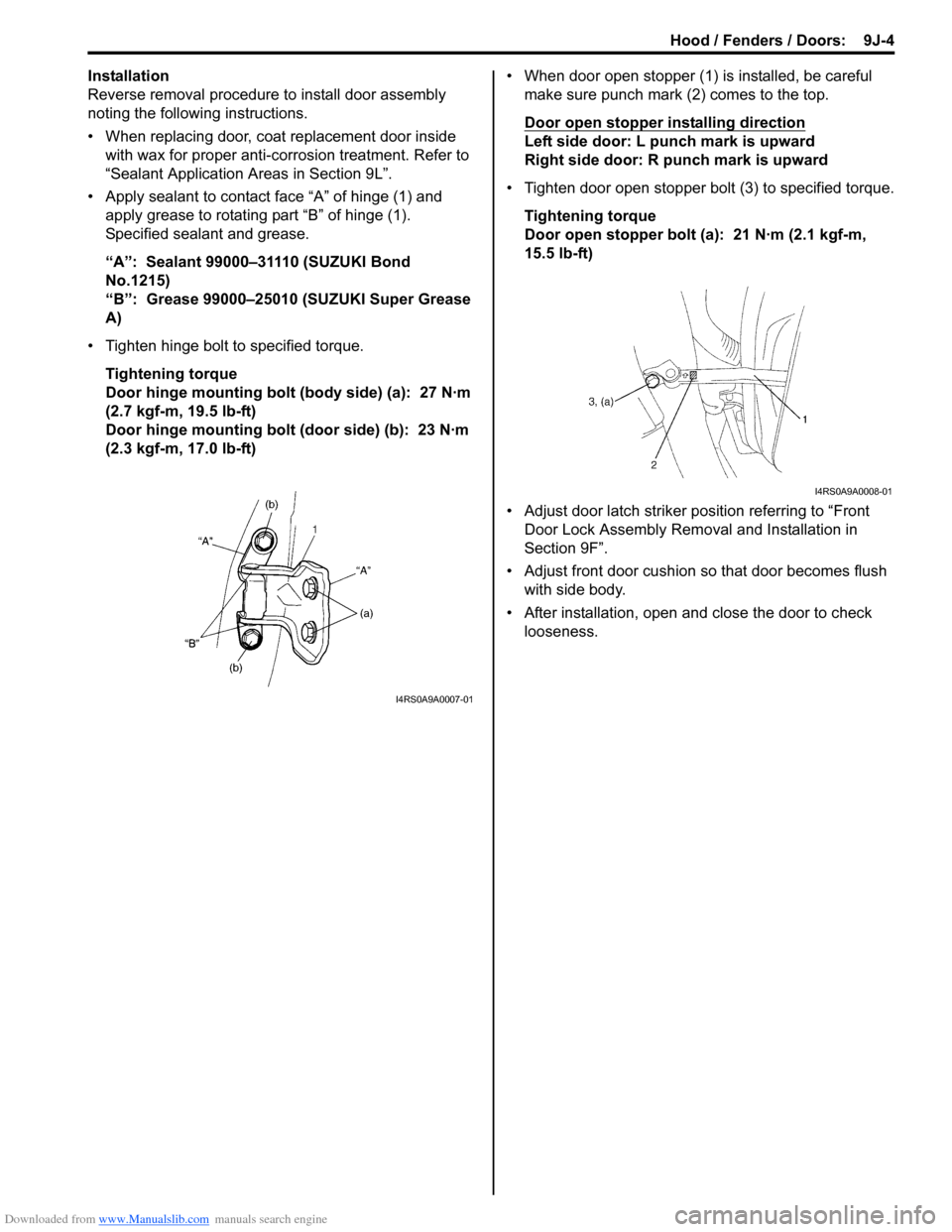
• Apply sealant to contact face “A” of hinge (1) and apply grease to rotating part “B” of hinge (1).
Specified sealant and grease.
“A”: Sealant 99000–31110 (SUZUKI Bond
No.1215)
“B”: Grease 99000–25010 (SUZUKI Super Grease
A)
• Tighten hinge bolt to specified torque. Tightening torque
Door hinge mounting bolt (body side) (a): 27 N·m
(2.7 kgf-m, 19.5 lb-ft)
Door hinge mounting bolt (door side) (b): 23 N·m
(2.3 kgf-m, 17.0 lb-ft) • When door open stopper (1) is installed, be careful
make sure punch mark (2) comes to the top.
Door open stopper installing direction
Left side door: L punch mark is upward
Right side door: R punch mark is upward
• Tighten door open stopper bolt (3) to specified torque. Tightening torque
Door open stopper bolt (a): 21 N·m (2.1 kgf-m,
15.5 lb-ft)
• Adjust door latch striker position referring to “Front Door Lock Assembly Removal and Installation in
Section 9F”.
• Adjust front door cushion so that door becomes flush with side body.
• After installation, open and close the door to check looseness.
I4RS0A9A0007-01
I4RS0A9A0008-01
Page 1374 of 1496
Downloaded from www.Manualslib.com manuals search engine 9J-5 Hood / Fenders / Doors:
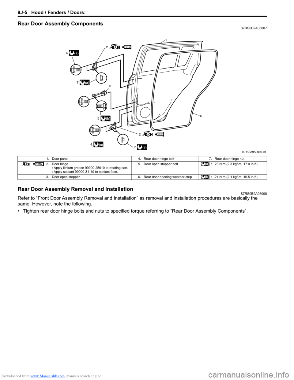
Rear Door Assembly ComponentsS7RS0B9A06007
Rear Door Assembly Removal and InstallationS7RS0B9A06008
Refer to “Front Door Assembly Removal and Installation” as removal and installation procedures are basically the
same. However, note the following.
• Tighten rear door hinge bolts and nuts to specified torque referring to “Rear Door Assembly Components”.
2
2
(a)4
(a)4
(a)7
(a)7
(b)53
6
1
I4RS0A9A0009-01
1. Door panel 4. Rear door hinge bolt7. Rear door hinge nut
2. Door hinge : Apply lithium grease 99000-25010 to rotating part.
: Apply sealant 99000-31110 to contact face. 5. Door open stopper bolt
: 23 N⋅m (2.3 kgf-m, 17.0 lb-ft)
3. Door open stopper 6. Rear door opening weather-strip: 21 N⋅m (2.1 kgf-m, 15.5 lb-ft)