low SUZUKI SWIFT 2007 2.G Service Workshop Manual
[x] Cancel search | Manufacturer: SUZUKI, Model Year: 2007, Model line: SWIFT, Model: SUZUKI SWIFT 2007 2.GPages: 1496, PDF Size: 34.44 MB
Page 1467 of 1496
Downloaded from www.Manualslib.com manuals search engine Keyless Start System: 10E-5
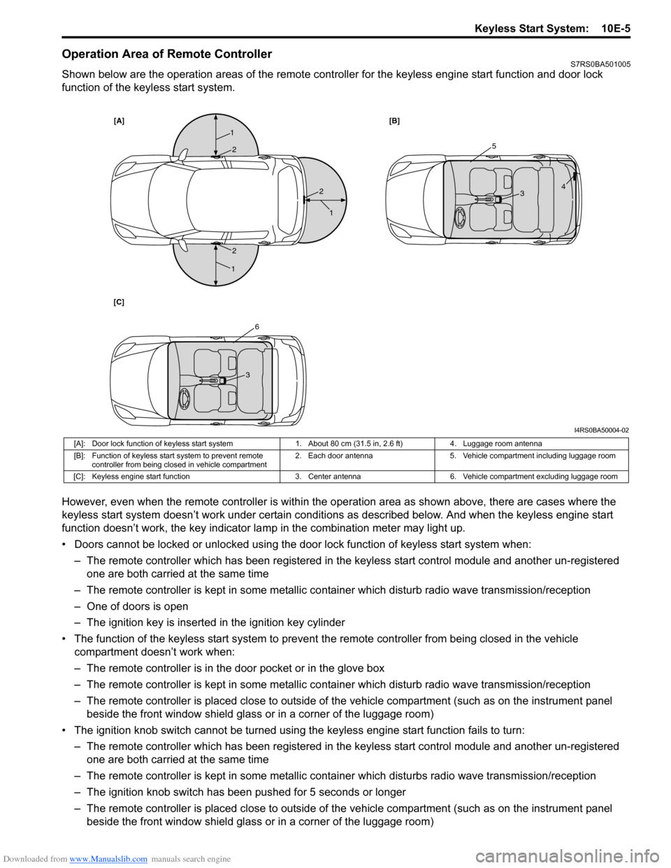
Operation Area of Remote ControllerS7RS0BA501005
Shown below are the operation areas of the remote controller for the keyless engine start function and door lock
function of the keyless start system.
However, even when the remote controller is within the operation area as shown above, there are cases where the
keyless start system doesn’t work under certain conditi ons as described below. And when the keyless engine start
function doesn’t work, the key indicator la mp in the combination meter may light up.
• Doors cannot be locked or unlocked using the doo r lock function of keyless start system when:
– The remote controller which has been registered in the keyless start control module and another un-registered one are both carried at the same time
– The remote controller is kept in some metallic co ntainer which disturb radio wave transmission/reception
– One of doors is open
– The ignition key is inserted in the ignition key cylinder
• The function of the keyless start system to prevent the remote controller from being closed in the vehicle
compartment doesn’t work when:
– The remote controller is in the door pocket or in the glove box
– The remote controller is kept in some metallic co ntainer which disturb radio wave transmission/reception
– The remote controller is placed close to outside of the vehicle compartment (such as on the instrument panel beside the front window shield glass or in a corner of the luggage room)
• The ignition knob switch cannot be turned usin g the keyless engine start function fails to turn:
– The remote controller which has been registered in the keyless start control module and another un-registered one are both carried at the same time
– The remote controller is kept in some metallic cont ainer which disturbs radio wave transmission/reception
– The ignition knob switch has been pushed for 5 seconds or longer
– The remote controller is placed close to outside of the vehicle compartment (such as on the instrument panel beside the front window shield glass or in a corner of the luggage room)
[A] [B]
[C]
1
1
1
25
6
3
3 4
2
2
I4RS0BA50004-02
[A]: Door lock function of keyless start system 1. About 80 cm (31.5 in, 2.6 ft)4. Luggage room antenna
[B]: Function of keyless start system to prevent remote controller from being closed in vehicle compartment 2. Each door antenna
5. Vehicle compartment including luggage room
[C]: Keyless engine start function 3. Center antenna6. Vehicle compartment excluding luggage room
Page 1468 of 1496
Downloaded from www.Manualslib.com manuals search engine 10E-6 Keyless Start System:
Alarm FunctionS7RS0BA501006
Under conditions as described in the table below, the keyless start control module makes the key indicator lamp flash
in red and the buzzer sound to call the driver’s attention.
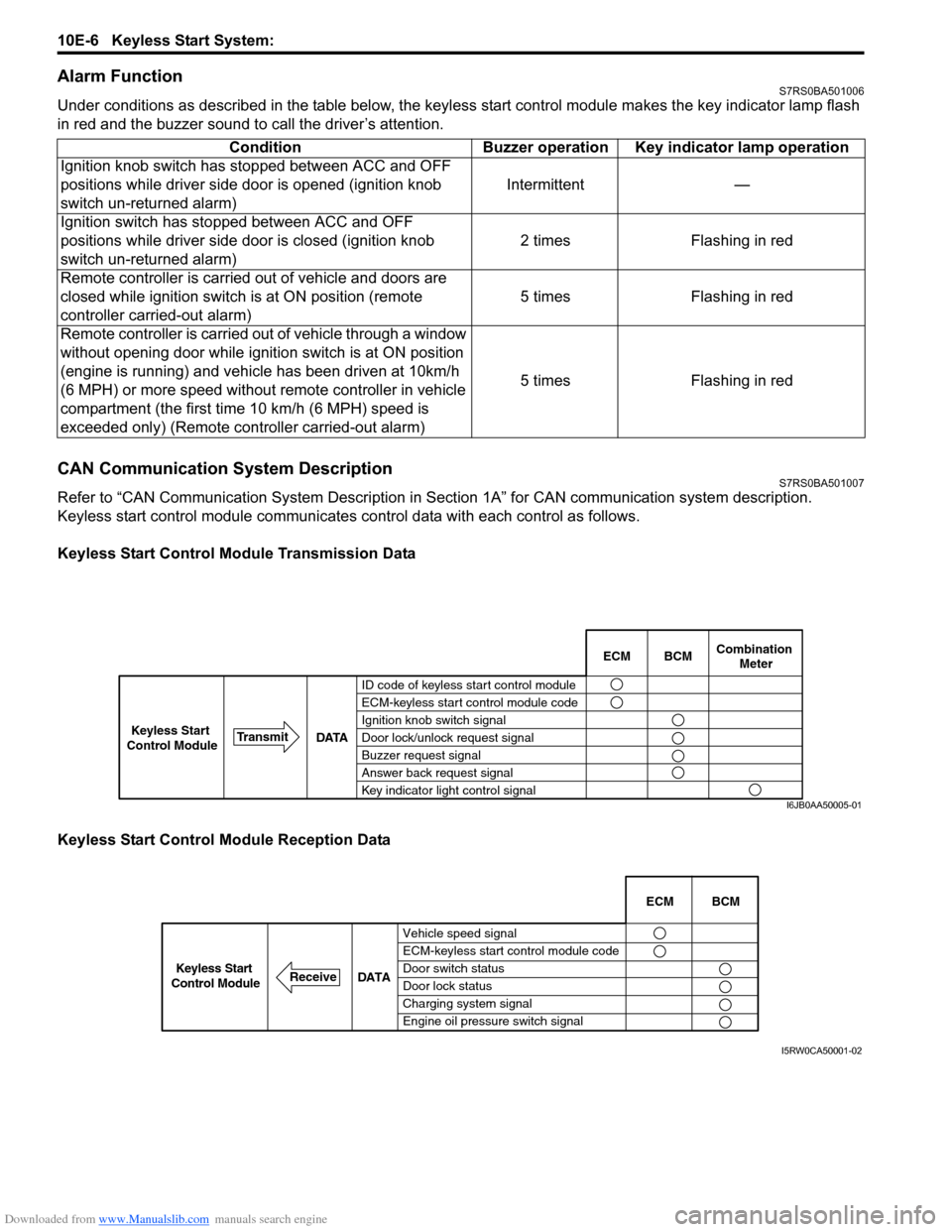
CAN Communication System DescriptionS7RS0BA501007
Refer to “CAN Communication System Description in Section 1A” for CAN communication system description.
Keyless start control module communicates control data wit h each control as follows.
Keyless Start Control Module Transmission Data
Keyless Start Control Module Reception Data Condition Buzzer operation Key indicator lamp operation
Ignition knob switch has stopped between ACC and OFF
positions while driver side door is opened (ignition knob
switch un-returned alarm) Intermittent —
Ignition switch has stopped between ACC and OFF
positions while driver side door is closed (ignition knob
switch un-returned alarm) 2 times Flashing in red
Remote controller is carried out of vehicle and doors are
closed while ignition switch is at ON position (remote
controller carried-out alarm) 5 times Flashing in red
Remote controller is carried out of vehicle through a window
without opening door while ignition switch is at ON position
(engine is running) and vehicle has been driven at 10km/h
(6 MPH) or more speed without remote controller in vehicle
compartment (the first time 10 km/h (6 MPH) speed is
exceeded only) (Remote cont roller carried-out alarm) 5 times Flashing in red
BCM
ECM Combination
Meter
ID code of keyless start control module
ECM-keyless start control module code
Ignition knob switch signal
Door lock/unlock request signal
Buzzer request signal
Answer back request signal
Key indicator light control signal
DATA
Transmit
Keyless Start
Control Module
I6JB0AA50005-01
Vehicle speed signal
ECM-keyless start control module code
Door switch status
Door lock status
Charging system signal
Engine oil pressure switch signal ECM BCM
DATA
ReceiveKeyless Start
Control Module
I5RW0CA50001-02
Page 1470 of 1496
Downloaded from www.Manualslib.com manuals search engine 10E-8 Keyless Start System:
Diagnostic Information and Procedures
Precautions in Diagnosing TroublesS7RS0BA504001
• The keyless start system executes data transmission/reception by means of th e radio wave. Therefore,
proper operation may not be obtained if use of the
door lock function and engine start function of the
keyless start system is attempted near the place
where strong radio wave is emitted (TV and radio
broadcasting stations, etc.).
• Diagnostic information stored in keyless start control
module memory can be checked only by key indicator
lamp.
• Be sure to use the trouble diagnosis procedure as described in “Keyless Start System Check”. Failure to
follow it may result in incorrect diagnosis. (Some other
DTC may be stored by mistake in the memory of
keyless start control module during inspection.)
• Be sure to read “Precautions for Electrical Circuit Service in Section 00” befo re inspection and observe
what is written there.
• Communication of ECM, BCM, TCM (A/T model), ABS control module, keyless start control module and
combination meter is estab lished by CAN (Controller
Area Network). (For detail of CAN communication for
keyless start control module, refer to “CAN
Communication System Description”). Therefore,
handle CAN communication line with care referring to
“Precaution for CAN Communication System in
Section 00”. • Replacement of the keyless start control module
When keyless start control module is replaced with
new one, make sure that r egister remote controller ID
code to keyless start co ntrol module correctly
according to “Registration Procedure for Remote
Controller ID Code”.
• Keyless start control module substitution When the keyless start control module used in
another vehicle was installed in the vehicle, register
the ID code of the remote controller in the keyless
start control module as well as the ignition key
transponder code fo r the immobilizer control system in
ECM. For the registration procedure of the ignition key
transponder code, refer to “Registration of the Ignition
Key in Section 10C”.
Self-Diagnosis FunctionS7RS0BA504002
The keyless start control module has self-diagnosis
function to monitor the system components and circuits
while the keyless start system is at work. When the
keyless start control module detects an abnormality in
the system, it saves the ar ea where such abnormality
has occurred as a DTC in its memory. The DTC stored in
memory of the keyless start control module is indicated
by the key indicator lamp in the combination meter
flashing in a specific pattern. For DTC indication, refer to
“DTC Check” and for the clearing procedure, to “DTC
Clearance”.
Keyless Start System Diagnosis IntroductionS7RS0BA504003
To ensure that the trouble diagnosis is done accurately
and smoothly, observe “Precautions in Diagnosing
Troubles” and follow “Keyless Start System Check”.
Keyless Start System CheckS7RS0BA504004
Step Action YesNo
1 1) Record details of the problem. For your record, use of a questionnaire form will facilit ate collecting information for
proper analysis and diagnosis.
2) Check if the problem described in “Customer Questionnaire (Example)” actually occurs in the vehicle.
(This step should be performed with the customer if
possible.)
Perform “Keyless Start System Operation Inspection”
procedure to check if the symptom which has occurred is
abnormal or not.
3) Check for DTC referring to “DTC Check”, and then record DTC(s).
4) Clear DTC referring to “DTC Clearance” if any DTC exists, and then recheck for DTC.
Is any DTC still detected? Go to Step 2.
Go to Step 3.
2 1) Check and repair referring to applicable “DTC Table”. Are check and repair complete? Go to Step 5.
Check and repair
malfunction part(s), and
go to Step 5.
Page 1472 of 1496
Downloaded from www.Manualslib.com manuals search engine 10E-10 Keyless Start System:
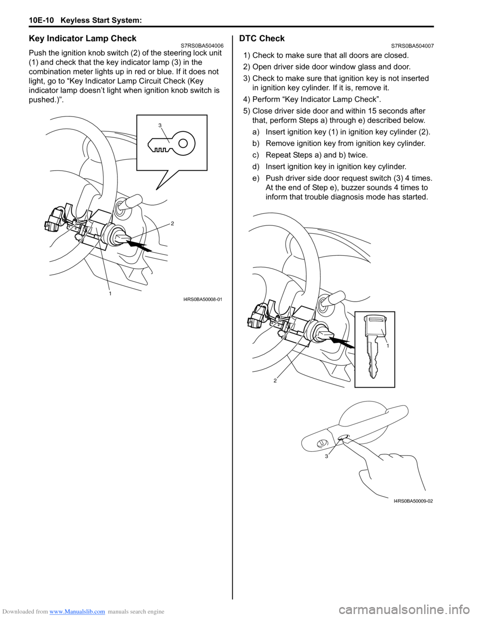
Key Indicator Lamp CheckS7RS0BA504006
Push the ignition knob switch (2) of the steering lock unit
(1) and check that the key indicator lamp (3) in the
combination meter lights up in red or blue. If it does not
light, go to “Key Indicator Lamp Circuit Check (Key
indicator lamp doesn’t light when ignition knob switch is
pushed.)”.
DTC CheckS7RS0BA504007
1) Check to make sure that all doors are closed.
2) Open driver side door window glass and door.
3) Check to make sure that ignition key is not inserted in ignition key cylinder. If it is, remove it.
4) Perform “Key Indicator Lamp Check”.
5) Close driver side door and within 15 seconds after that, perform Steps a) through e) described below.
a) Insert ignition key (1) in ignition key cylinder (2).
b) Remove ignition key from ignition key cylinder.
c) Repeat Steps a) and b) twice.
d) Insert ignition key in ignition key cylinder.
e) Push driver side door request switch (3) 4 times. At the end of Step e), buzzer sounds 4 times to
inform that trouble diagnosis mode has started.
3
1
2
I4RS0BA50008-01
2
1
3
I4RS0BA50009-02
Page 1473 of 1496
Downloaded from www.Manualslib.com manuals search engine Keyless Start System: 10E-11
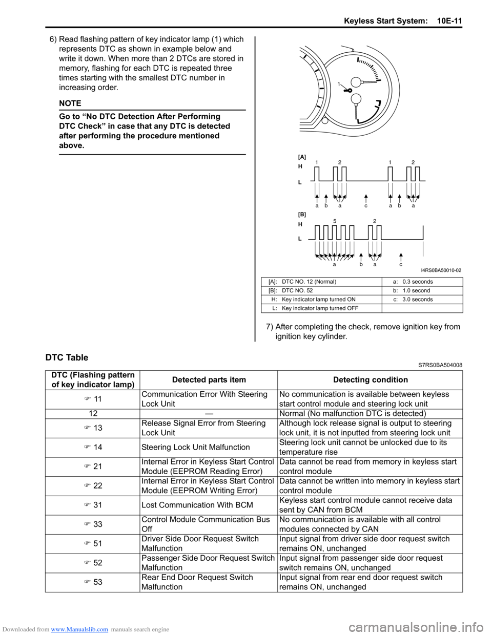
6) Read flashing pattern of key indicator lamp (1) which represents DTC as shown in example below and
write it down. When more than 2 DTCs are stored in
memory, flashing for each DTC is repeated three
times starting with the smallest DTC number in
increasing order.
NOTE
Go to “No DTC Detect ion After Performing
DTC Check” in case that any DTC is detected
after performing the procedure mentioned
above.
7) After completing the check, remove ignition key from ignition key cylinder.
DTC TableS7RS0BA504008
[A]: DTC NO. 12 (Normal)
a: 0.3 seconds
[B]: DTC NO. 52 b: 1.0 second
H: Key indicator lamp tu rned ONc: 3.0 seconds
L: Key indicator lamp turned OFF
bc
a
a
[A]
H
L
H
L [B]
52
bac
a
2
11baa 2
1
I4RS0BA50010-02
DTC (Flashing pattern
of key indicator lamp) Detected parts item Detecting condition
) 11 Communication Error With Steering
Lock Unit No communication is available between keyless
start control module and steering lock unit
12 — Normal (No malfunct ion DTC is detected)
) 13 Release Signal Error from Steering
Lock Unit Although lock release signal is output to steering
lock unit, it is not inputt
ed from steering lock unit
) 14 Steering Lock Unit Malfunction Steering lock unit cannot be unlocked due to its
temperature rise
) 21 Internal Error in Ke
yless Start Control
Module (EEPROM Reading Error) Data cannot be read from memory in keyless start
control module
) 22 Internal Error in Ke
yless Start Control
Module (EEPROM Writing Error) Data cannot be written into memory in keyless start
control module
) 31 Lost Communication With BCM Keyless start control module cannot receive data
sent by CAN from BCM
) 33 Control Module Communication Bus
Off No communication is available with all control
modules connected by CAN
) 51 Driver Side Door Request Switch
Malfunction Input signal from driver side door request switch
remains ON, unchanged
) 52 Passenger Side Door Request Switch
Malfunction Input signal from passenger side door request
switch remains ON, unchanged
) 53 Rear End Door Request Switch
Malfunction Input signal from rear end door request switch
remains ON, unchanged
Page 1474 of 1496
Downloaded from www.Manualslib.com manuals search engine 10E-12 Keyless Start System:
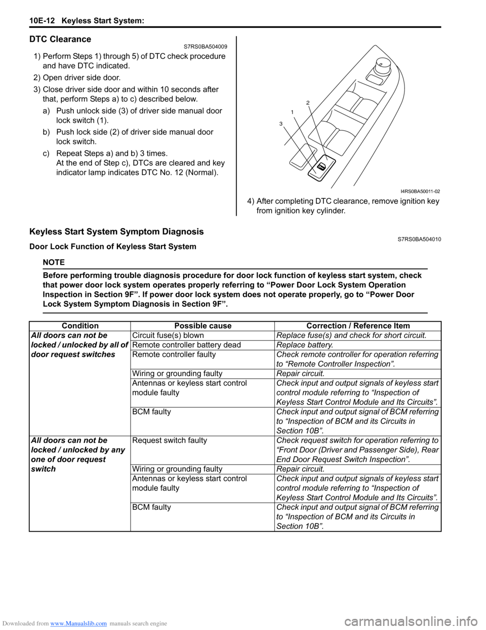
DTC ClearanceS7RS0BA504009
1) Perform Steps 1) through 5) of DTC check procedure and have DTC indicated.
2) Open driver side door.
3) Close driver side door and within 10 seconds after that, perform Steps a) to c) described below.
a) Push unlock side (3) of driver side manual door lock switch (1).
b) Push lock side (2) of driver side manual door lock switch.
c) Repeat Steps a) and b) 3 times. At the end of Step c), DTCs are cleared and key
indicator lamp indicates DTC No. 12 (Normal).
4) After completing DTC clearance, remove ignition key from ignition key cylinder.
Keyless Start System Symptom DiagnosisS7RS0BA504010
Door Lock Function of Keyless Start System
NOTE
Before performing trouble diagnosis procedure for door lock function of keyless start system, check
that power door lock system operates properly referring to “Power Door Lock System Operation
Inspection in Section 9F”. If power door lock system does not operate properly, go to “Power Door
Lock System Symptom Diagnosis in Section 9F”.
1
3 2
I4RS0BA50011-02
Condition
Possible cause Correction / Reference Item
All doors can not be
locked / unlocked by all of
door request switches Circuit fuse(s) blown
Replace fuse(s) and check for short circuit.
Remote controller battery dead Replace battery.
Remote controller faulty Check remote controller for operation referring
to “Remote Controller Inspection”.
Wiring or grounding faulty Repair circuit.
Antennas or keyless start control
module faulty Check input and output signals of keyless start
control module referring to “Inspection of
Keyless Start Control Mo
dule and Its Circuits”.
BCM faulty Check input and output signal of BCM referring
to “Inspection of BCM and its Circuits in
Section 10B”.
All doors can not be
locked / unlocked by any
one of door request
switch Request switch faulty
Check request switch for operation referring to
“Front Door (Driver and Passenger Side), Rear
End Door Request Switch Inspection”.
Wiring or grounding faulty Repair circuit.
Antennas or keyless start control
module faulty Check input and output signals of keyless start
control module referring to “Inspection of
Keyless Start Control Mo
dule and Its Circuits”.
BCM faulty Check input and output signal of BCM referring
to “Inspection of BCM and its Circuits in
Section 10B”.
Page 1475 of 1496
Downloaded from www.Manualslib.com manuals search engine Keyless Start System: 10E-13
Keyless Engine Start Function
NOTE
Before performing symptom diagnosis procedure for keyless engine start system, check that engine
starts by using ignition key. If it cannot be started by using ignition key, go to “Engine Symptom
Diagnosis in Section 1A”.
Keyless Start System Operation InspectionS7RS0BA504011
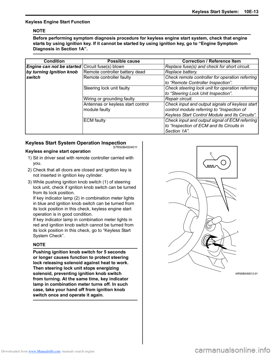
Keyless engine start operation
1) Sit in driver seat with re mote controller carried with
you.
2) Check that all doors are closed and ignition key is not inserted in ignition key cylinder.
3) While pushing ignition knob switch (1) of steering lock unit, check if ignition knob switch can be turned
from its lock position.
If key indicator lamp (2) in combination meter lights
in blue and ignition knob switch can be turned from
its lock position in this check, keyless engine start
operation is in good condition.
If key indicator lamp in combination meter lights in
red and ignition knob switch cannot be turned from
its lock position in this check, go to “Keyless Start
System Check”.
NOTE
Pushing ignition knob switch for 5 seconds
or longer causes function to protect steering
lock releasing solenoid against heat to work.
Then steering lock unit stops energizing
solenoid, preventing ignition knob switch
from turning. At the same time, key indicator
lamp in combination mete r turns off. In such
case, take your hand off from ignition knob
switch once and operate it again.
Condition Possible cause Correction / Reference Item
Engine can not be started
by turning Ignition knob
switch Circuit fuse(s) blown
Replace fuse(s) and check for short circuit.
Remote controller battery dead Replace battery.
Remote controller faulty Check remote controller for operation referring
to “Remote Controller Inspection”.
Steering lock unit faulty Check steering lock unit for operation referring
to “Steering Lock Unit Inspection”.
Wiring or grounding faulty Repair circuit.
Antennas or keyless start control
module faulty Check input and output signals of keyless start
control module referring to “Inspection of
Keyless Start Control Mo
dule and Its Circuits”.
ECM faulty Check input and output signal of ECM referring
to “Inspection of ECM and Its Circuits in
Section 1A”.
1
2
I4RS0BA50012-01
Page 1477 of 1496
Downloaded from www.Manualslib.com manuals search engine Keyless Start System: 10E-15
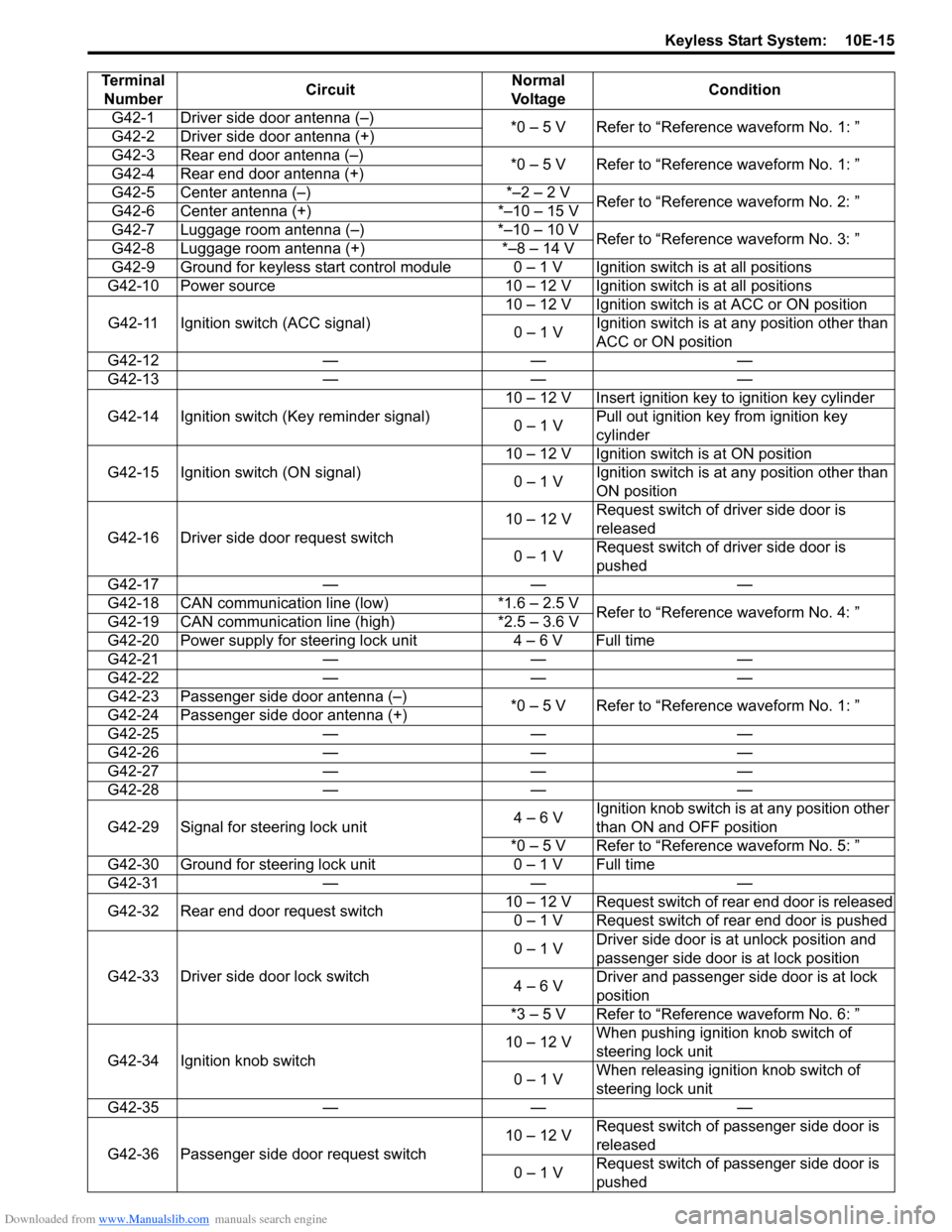
Terminal Number Circuit Normal
Vo l ta g e Condition
G42-1 Driver side door antenna (–) *0 – 5 V Refer to “Reference waveform No. 1: ”
G42-2 Driver side door antenna (+)
G42-3 Rear end door antenna (–) *0 – 5 V Refer to “Reference waveform No. 1: ”
G42-4 Rear end door antenna (+)
G42-5 Center antenna (–) *–2 – 2 V Refer to “Reference waveform No. 2: ”
G42-6 Center antenna (+) *–10 – 15 V
G42-7 Luggage room antenna (–) *–10 – 10 V Refer to “Reference waveform No. 3: ”
G42-8 Luggage room antenna (+) *–8 – 14 V
G42-9 Ground for keyless start control module 0 – 1 V Ignition switch is at all positions
G42-10 Power source 10 – 12 V Ignition switch is at all positions
G42-11 Ignition switch (ACC signal) 10 – 12 V Ignition switch is at ACC or ON position
0 – 1 V Ignition switch is at any position other than
ACC or ON position
G42-12 — — —
G42-13 — — —
G42-14 Ignition switch (Key reminder signal) 10 – 12 V Insert ignition key to ignition key cylinder
0 – 1 V Pull out ignition key from ignition key
cylinder
G42-15 Ignition switch (ON signal) 10 – 12 V Ignition switch is at ON position
0 – 1 V Ignition switch is at any position other than
ON position
G42-16 Driver side door request switch 10 – 12 V
Request switch of driver side door is
released
0 – 1 V Request switch of driver side door is
pushed
G42-17 — — —
G42-18 CAN communication line (low) *1.6 – 2.5 V Refer to “Reference waveform No. 4: ”
G42-19 CAN communication line (high) *2.5 – 3.6 V
G42-20 Power supply for steering lock unit 4 – 6 V Full time
G42-21 — — —
G42-22 — — —
G42-23 Passenger side door antenna (–) *0 – 5 V Refer to “Reference waveform No. 1: ”
G42-24 Passenger side door antenna (+)
G42-25 — — —
G42-26 — — —
G42-27 — — —
G42-28 — — —
G42-29 Signal for steering lock unit 4 – 6 VIgnition knob switch is at any position other
than ON and OFF position
*0 – 5 V Refer to “Reference waveform No. 5: ”
G42-30 Ground for steering lock unit 0 – 1 V Full time
G42-31 — — —
G42-32 Rear end door request switch 10 – 12 V Request switch of rear end door is released
0 – 1 V Request switch of rear end door is pushed
G42-33 Driver side door lock switch 0 – 1 V
Driver side door is at unlock position and
passenger side door is at lock position
4 – 6 V Driver and passenger side door is at lock
position
*3 – 5 V Refer to “Reference waveform No. 6: ”
G42-34 Ignition knob switch 10 – 12 V
When pushing ignition knob switch of
steering lock unit
0 – 1 V When releasing ignition knob switch of
steering lock unit
G42-35 — — —
G42-36 Passenger side door request switch 10 – 12 V
Request switch of passenger side door is
released
0 – 1 V Request switch of passenger side door is
pushed
Page 1479 of 1496
Downloaded from www.Manualslib.com manuals search engine Keyless Start System: 10E-17
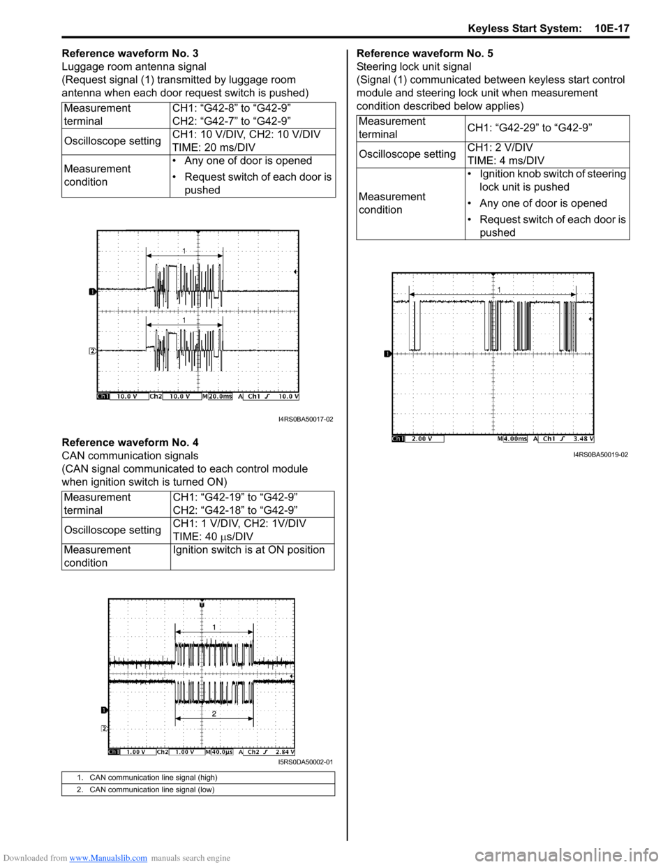
Reference waveform No. 3
Luggage room antenna signal
(Request signal (1) transmitted by luggage room
antenna when each door request switch is pushed)
Reference waveform No. 4
CAN communication signals
(CAN signal communicated to each control module
when ignition switch is turned ON)Reference waveform No. 5
Steering lock unit signal
(Signal (1) communicated between keyless start control
module and steering lock unit when measurement
condition described below applies)
Measurement
terminal CH1: “G42-8” to “G42-9”
CH2: “G42-7” to “G42-9”
Oscilloscope setting CH1: 10 V/DIV, CH2: 10 V/DIV
TIME: 20 ms/DIV
Measurement
condition • Any one of door is opened
• Request switch of each door is
pushed
Measurement
terminal CH1: “G42-19” to “G42-9”
CH2: “G42-18” to “G42-9”
Oscilloscope setting CH1: 1 V/DIV, CH2: 1V/DIV
TIME: 40
µs/DIV
Measurement
condition Ignition switch is at ON position
1. CAN communication line signal (high)
2. CAN communication line signal (low)
I4RS0BA50017-02
I5RS0DA50002-01
Measurement
terminal
CH1: “G42-29” to “G42-9”
Oscilloscope setting CH1: 2 V/DIV
TIME: 4 ms/DIV
Measurement
condition • Ignition knob switch of steering
lock unit is pushed
• Any one of door is opened
• Request switch of each door is pushed
I4RS0BA50019-02
Page 1484 of 1496
Downloaded from www.Manualslib.com manuals search engine 10E-22 Keyless Start System:
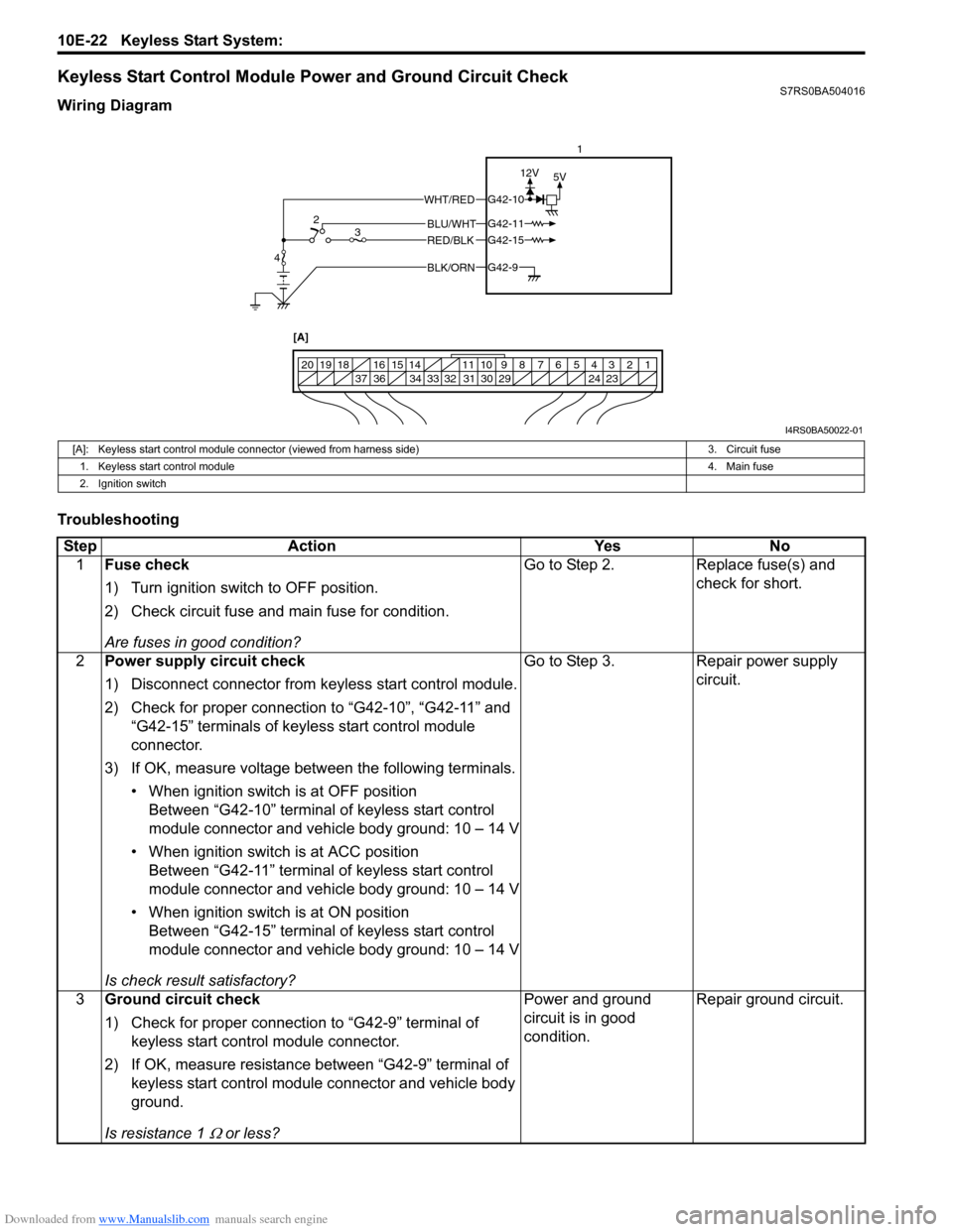
Keyless Start Control Module Power and Ground Circuit CheckS7RS0BA504016
Wiring Diagram
Troubleshooting
BLK/ORNG42-9
G42-15
G42-10
G42-11BLU/WHT
WHT/RED
RED/BLK
5V
12V
1234567891011
141516
36 34 33 32 31 30 29 24 23
37
181920
[A]
4 2
3 1
I4RS0BA50022-01
[A]: Keyless start control module connector (viewed from harness side)
3. Circuit fuse
1. Keyless start control module 4. Main fuse
2. Ignition switch
Step Action YesNo
1 Fuse check
1) Turn ignition switch to OFF position.
2) Check circuit fuse and main fuse for condition.
Are fuses in good condition? Go to Step 2.
Replace fuse(s) and
check for short.
2 Power supply circuit check
1) Disconnect connector from keyless start control module.
2) Check for proper connection to “G42-10”, “G42-11” and
“G42-15” terminals of keyless start control module
connector.
3) If OK, measure voltage between the following terminals. • When ignition switch is at OFF positionBetween “G42-10” terminal of keyless start control
module connector and vehicle body ground: 10 – 14 V
• When ignition switch is at ACC position Between “G42-11” terminal of keyless start control
module connector and vehicle body ground: 10 – 14 V
• When ignition switch is at ON position Between “G42-15” terminal of keyless start control
module connector and vehicle body ground: 10 – 14 V
Is check result satisfactory? Go to Step 3.
Repair power supply
circuit.
3 Ground circuit check
1) Check for proper connection to “G42-9” terminal of
keyless start control module connector.
2) If OK, measure resistance between “G42-9” terminal of keyless start control module connector and vehicle body
ground.
Is resistance 1
Ω or less? Power and ground
circuit is in good
condition.
Repair ground circuit.