low SUZUKI SWIFT 2007 2.G Service Workshop Manual
[x] Cancel search | Manufacturer: SUZUKI, Model Year: 2007, Model line: SWIFT, Model: SUZUKI SWIFT 2007 2.GPages: 1496, PDF Size: 34.44 MB
Page 1440 of 1496
Downloaded from www.Manualslib.com manuals search engine 10B-37 Body Electrical Control System:
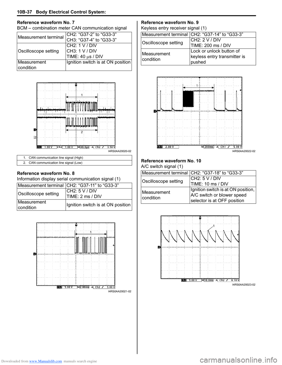
Reference waveform No. 7
BCM – combination meter CAN communication signal
Reference waveform No. 8
Information display serial communication signal (1)Reference waveform No. 9
Keyless entry receiver signal (1)
Reference waveform No. 10
A/C switch signal (1)
Measurement terminal
CH2: “G37-2” to “G33-3”
CH3: “G37-4” to “G33-3”
Oscilloscope setting CH2: 1 V / DIV
CH3: 1 V / DIV
TIME: 40
µs / DIV
Measurement
condition Ignition switch is at ON position
1. CAN communication line signal (High)
2. CAN communication line signal (Low)
Measurement terminal CH2: “G37-11” to “G33-3”
Oscilloscope setting
CH2: 5 V / DIV
TIME: 2 ms / DIV
Measurement
condition Ignition switch is at ON position
I4RS0AA20020-02
I4RS0AA20021-02
Measurement terminal CH2: “G37-14” to “G33-3”
Oscilloscope settingCH2: 2 V / DIV
TIME: 200 ms / DIV
Measurement
condition Lock or unlock button of
keyless entry transmitter is
pushed
Measurement terminal CH2: “G37-18” to “G33-3”
Oscilloscope setting CH2: 5 V / DIV
TIME: 10 ms / DIV
Measurement
condition Ignition switch is at ON position,
A/C switch or blower speed
selector is at OFF position
I4RS0AA20022-02
I4RS0AA20023-02
Page 1441 of 1496
Downloaded from www.Manualslib.com manuals search engine Body Electrical Control System: 10B-38
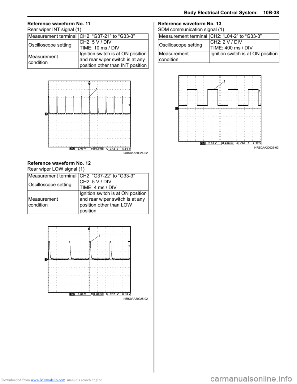
Reference waveform No. 11
Rear wiper INT signal (1)
Reference waveform No. 12
Rear wiper LOW signal (1)Reference waveform No. 13
SDM communication signal (1)
Measurement terminal CH2: “G37-21” to “G33-3”
Oscilloscope setting CH2: 5 V / DIV
TIME: 10 ms / DIV
Measurement
condition Ignition switch is at ON position
and rear wiper switch is at any
position other than INT position
Measurement terminal CH2: “G37-22” to “G33-3”
Oscilloscope setting CH2: 5 V / DIV
TIME: 4 ms / DIV
Measurement
condition Ignition switch is at ON position
and rear wiper switch is at any
position other than LOW
position
I4RS0AA20024-02
I4RS0AA20025-02
Measurement terminal CH2: “L04-2” to “G33-3”
Oscilloscope setting
CH2: 2 V / DIV
TIME: 400 ms / DIV
Measurement
condition Ignition switch is at ON position
I4RS0AA20026-02
Page 1442 of 1496

Downloaded from www.Manualslib.com manuals search engine 10B-39 Body Electrical Control System:
Repair Instructions
BCM (Included in Junction Block Assembly)
Removal and Installation
S7RS0BA206001
CAUTION!
Do not attempt removal of BCM from junction
block assembly as it may cause contact
failure.
If there is faulty condition in BCM, replace
junction block assembly.
Removal
1) Disconnect negative (–) cable from battery.
2) Disable air bag system referring to “Disabling Air Bag System in Section 8B”.
3) Remove dash side trim (1) and steering column hole cover (2).
4) Remove junction block assembly mounting nuts (3).
5) Disconnect connectors from BCM and junction block assembly.
6) Detach wiring harness clamp from junction block assembly.
Installation
Reverse removal procedure for installation, noting
following points.
• Connect connectors securely.
• Enable air bag system referring to “Enabling Air Bag System in Section 8B”.
Outside Air Temperature Sensor Removal and
Installation
S7RS0BA206002
For removal and installation, refer to “Outside Air
Temperature Sensor Removal and Installation (If
Equipped) in Section 9C”.
Outside Air Temperature Sensor InspectionS7RS0BA206003
For inspection, refer to “Outside Air Temperature Sensor
Inspection (If Equipped) in Section 9C”.
Security Alarm Mode Selection Procedure (If
Equipped)
S7RS0BA206004
Security alarm mode can be selected by performing the
following procedure.
1) Confirm that all doors are closed, all doors are unlocked and ignition key is inserted in ignition key
cylinder.
2) Remove ignition key from ignition key cylinder.
3) Perform Step a) through e) described below within 15 seconds.
a) Insert ignition key (1) in ignition key cylinder (2).
b) Remove ignition key from ignition key cylinder.
c) Repeat Step a) and b) twice.
d) Insert ignition key in ignition key cylinder.
e) Push lock side (3) of driver side manual lock switch (4) 3 times.
4) When Step 3) is completed, the mode changes to the next one automatically. The warning buzzer
(located in BCM) sounds by the number of specified
for each mode as follows.
• Changed from A mode to B mode: Buzzer sounds 4 times
• Changed from B mode to A mode: Buzzer sounds once
4. BCM 5. Junction block assembly
I4RS0BA20010-01
4
3
1
2
I5RS0DA20007-01
Page 1443 of 1496
Downloaded from www.Manualslib.com manuals search engine Body Electrical Control System: 10B-40
Special Tools and Equipment
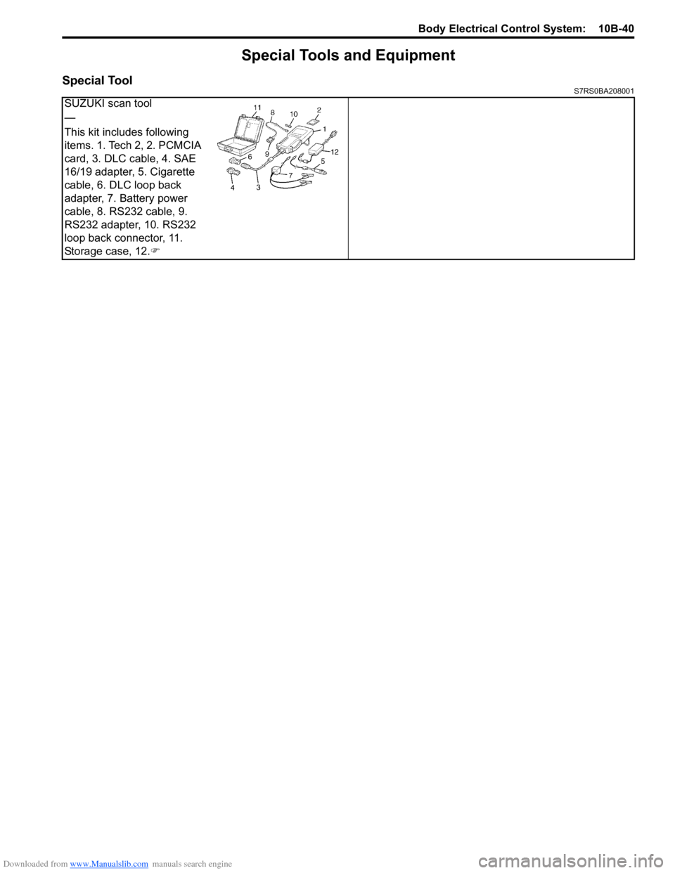
Special ToolS7RS0BA208001
SUZUKI scan tool
—
This kit includes following
items. 1. Tech 2, 2. PCMCIA
card, 3. DLC cable, 4. SAE
16/19 adapter, 5. Cigarette
cable, 6. DLC loop back
adapter, 7. Battery power
cable, 8. RS232 cable, 9.
RS232 adapter, 10. RS232
loop back connector, 11.
Storage case, 12.)
Page 1445 of 1496
Downloaded from www.Manualslib.com manuals search engine Immobilizer Control System: 10C-2
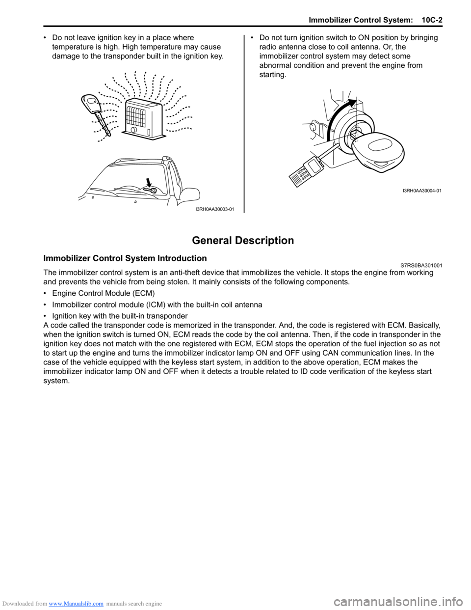
• Do not leave ignition key in a place where
temperature is high. High temperature may cause
damage to the transponder built in the ignition key. • Do not turn ignition switch to ON position by bringing
radio antenna close to coil antenna. Or, the
immobilizer control syst em may detect some
abnormal condition and prevent the engine from
starting.
General Description
Immobilizer Control System IntroductionS7RS0BA301001
The immobilizer control system is an anti-theft device that immobilizes the vehicle. It stops the engine from working
and prevents the vehicle from being stolen. It mainly consists of the following components.
• Engine Control Module (ECM)
• Immobilizer control module (ICM) with the built-in coil antenna
• Ignition key with the built-in transponder
A code called the transponder code is memorized in the tran sponder. And, the code is registered with ECM. Basically,
when the ignition switch is turned ON, ECM reads the code by the coil antenna. Then, if the code in transponder in the
ignition key does not match with the one registered with ECM, ECM stops the operati on of the fuel injection so as not
to start up the engine and turns the immobilizer indi cator lamp ON and OFF using CA N communication lines. In the
case of the vehicle equipped with the keyless start system , in addition to the above operation, ECM makes the
immobilizer indicator lamp ON and OFF when it detects a trouble related to ID code verification of the keyless start
system.
I3RH0AA30003-01
I3RH0AA30004-01
Page 1448 of 1496
Downloaded from www.Manualslib.com manuals search engine 10C-5 Immobilizer Control System:
Diagnostic Information and Procedures
Immobilizer Control System CheckS7RS0BA304001
Diagnostic Trouble Code (DTC) CheckS7RS0BA304002
NOTE
To know how to use SUZUKI scan tool in
detail, refer to its operator’s manual.
Using Scan Tool
1) Turn the ignition switch to OFF position.
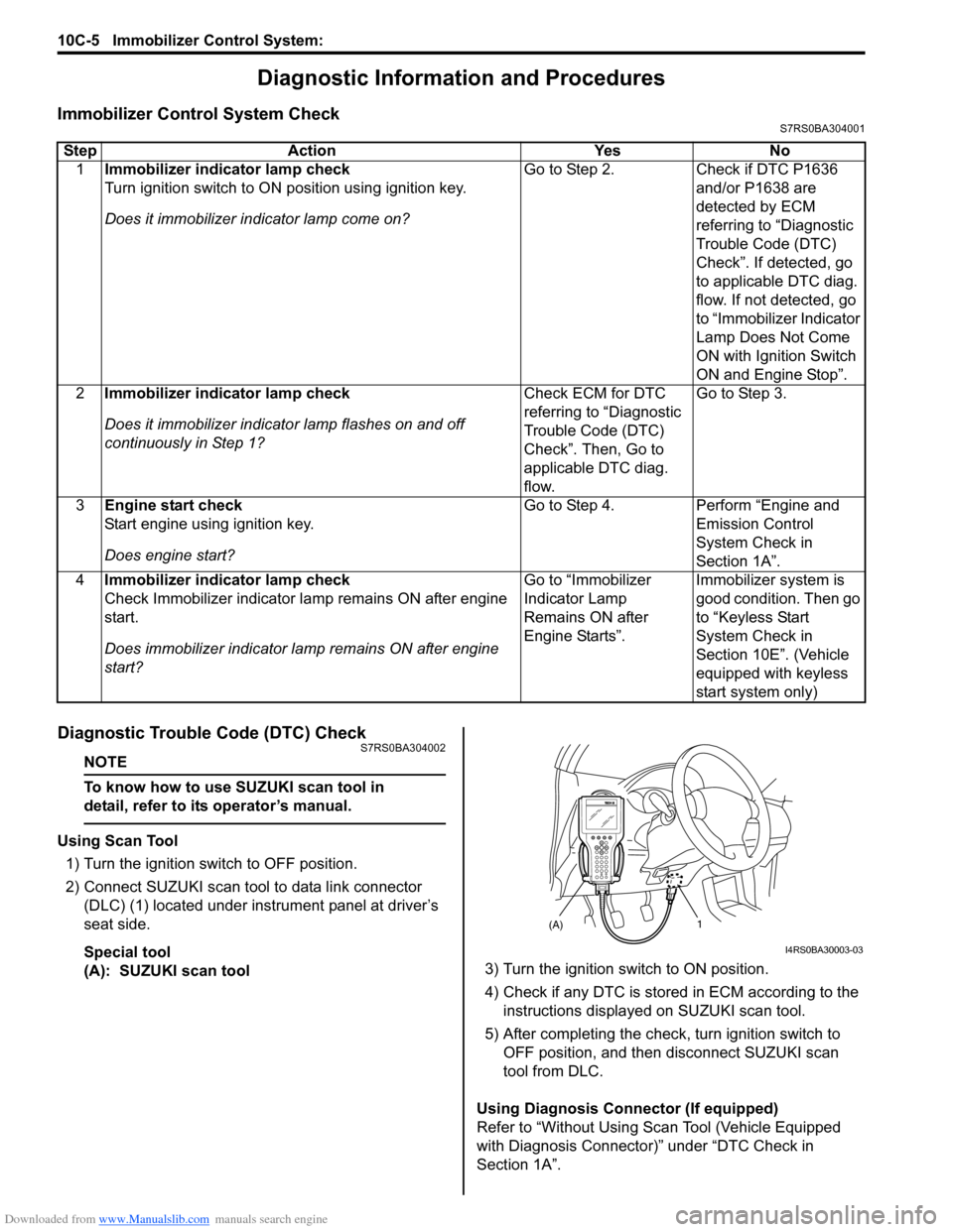
2) Connect SUZUKI scan tool to data link connector (DLC) (1) located under instrument panel at driver’s
seat side.
Special tool
(A): SUZUKI scan tool 3) Turn the ignition switch to ON position.
4) Check if any DTC is stored
in ECM according to the
instructions displayed on SUZUKI scan tool.
5) After completing the check, turn ignition switch to
OFF position, and then di sconnect SUZUKI scan
tool from DLC.
Using Diagnosis Connector (If equipped)
Refer to “Without Using Scan Tool (Vehicle Equipped
with Diagnosis Connector)” under “DTC Check in
Section 1A”.
Step Action Yes No
1 Immobilizer indicator lamp check
Turn ignition switch to ON position using ignition key.
Does it immobilizer in dicator lamp come on? Go to Step 2.
Check if DTC P1636
and/or P1638 are
detected by ECM
referring to “Diagnostic
Trouble Code (DTC)
Check”. If detected, go
to applicable DTC diag.
flow. If not detected, go
to “Immobilizer Indicator
Lamp Does Not Come
ON with Ignition Switch
ON and Engine Stop”.
2 Immobilizer indicator lamp check
Does it immobilizer indicato r lamp flashes on and off
continuously in Step 1? Check ECM for DTC
referring to “Diagnostic
Trouble Code (DTC)
Check”. Then, Go to
applicable DTC diag.
flow.Go to Step 3.
3 Engine start check
Start engine using ignition key.
Does engine start? Go to Step 4.
Perform “Engine and
Emission Control
System Check in
Section 1A”.
4 Immobilizer indicator lamp check
Check Immobilizer indicator la mp remains ON after engine
start.
Does immobilizer indicator la mp remains ON after engine
start? Go to “Immobilizer
Indicator Lamp
Remains ON after
Engine Starts”.
Immobilizer system is
good condition. Then go
to “Keyless Start
System Check in
Section 10E”. (Vehicle
equipped with keyless
start system only)
(A)1
I4RS0BA30003-03
Page 1450 of 1496
Downloaded from www.Manualslib.com manuals search engine 10C-7 Immobilizer Control System:
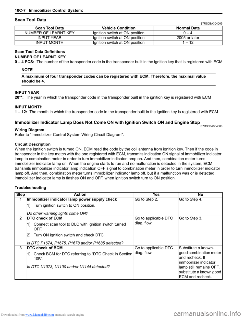
Scan Tool DataS7RS0BA304005
Scan Tool Data Definitions
NUMBER OF LEARNT KEY
0 – 4 PCS: The number of the transponder code in the transponder built in the ignition key that is registered with ECM
NOTE
A maximum of four transponder codes can be registered with ECM. Therefore, the maximal value
should be 4.
INPUT YEAR
20**: The year in which the transponder code in the transpon der built in the ignition key is registered with ECM
INPUT MONTH
1 – 12: The month in which the transponder code in the transpond er built in the ignition key is registered with ECM
Immobilizer Indicator Lamp Does Not Come ON with Ignition Switch ON and Engine StopS7RS0BA304006
Wiring Diagram
Refer to “Immobilizer Control System Wiring Circuit Diagram”.
Circuit Description
When the ignition switch is turned ON, ECM read the code by the coil antenna from ignition key. Then if the code in
transponder in the key match with the one registered with ECM, transmits indication ON signal of immobilizer indicator
lamp to combination meter in order to turn immobilizer indicator lamp on. And then, combination meter turns
immobilizer indicator lamp on. When th e engine starts to run and no malfunction is detected in the system, ECM
transmits immobilizer indi cator lamp indication OFF signal to combination meter in order to turn immobilizer indicator
lamp off. And then, comb ination meter turns immobilizer indicator lamp off, but if a malfunction was or is detected,
immobilizer indicator lamp is flashes ON and OF F, when ignition switch turn to ON position.
Troubleshooting Scan Tool Data Vehicl
e Condition Normal Data
NUMBER OF LEARNT KEY Ignition switch at ON position 0 – 4 INPUT YEAR Ignition switch at ON position 2005 or later
INPUT MONTH Ignition switch at ON position 1 – 12
Step Action YesNo
1 Immobilizer indicator lamp power supply check
1) Turn ignition switch to ON position.
Do other warning lights come ON? Go to Step 2.
Go to Step 4.
2 DTC check of ECM
1) Connect scan tool to DLC with ignition switch turned
OFF.
2) Turn ON ignition switch and check DTC.
Is DTC P1674, P1675, P1678 and/or P1685 detected? Go to applicable DTC
diag. flow.
Go to Step 3.
3 DTC check of BCM
1) Check BCM for DTC referring to “DTC Check in Section
10B”.
Is DTC U1073, U1100 and/or U1144 detected? Go to applicable DTC
diag. flow.
Substitute a known-
good combination meter
and recheck. If
immobilizer indicator
lamp still remains OFF,
substitute a known good
ECM and recheck.
Page 1451 of 1496
Downloaded from www.Manualslib.com manuals search engine Immobilizer Control System: 10C-8
Immobilizer Indicator Lamp Remains ON after Engine StartsS7RS0BA304007
Wiring Diagram
Refer to “Immobilizer Control S ystem Wiring Circuit Diagram”.
Circuit Description
When the ignition switch is turned ON, ECM read the code by the coil antenna from ignition key. Then if the code in
transponder in the key match with the one registered with ECM, transmits indication ON signal of immobilizer indicator
lamp to combination meter in order to turn immobilizer indicator lamp on. And then, combination meter turns
immobilizer indicator lamp on. When th e engine starts to run and no malfunction is detected in the system, ECM
transmits immobilizer indicator lamp indication O FF signal to combination meter in order to turn immobilizer indicator
lamp off. And then, comb ination meter turns immobilizer indicator lamp off, but if a malfunction was or is detected,
immobilizer indicator lamp is flashes ON and OF F, when ignition switch turn to ON position.
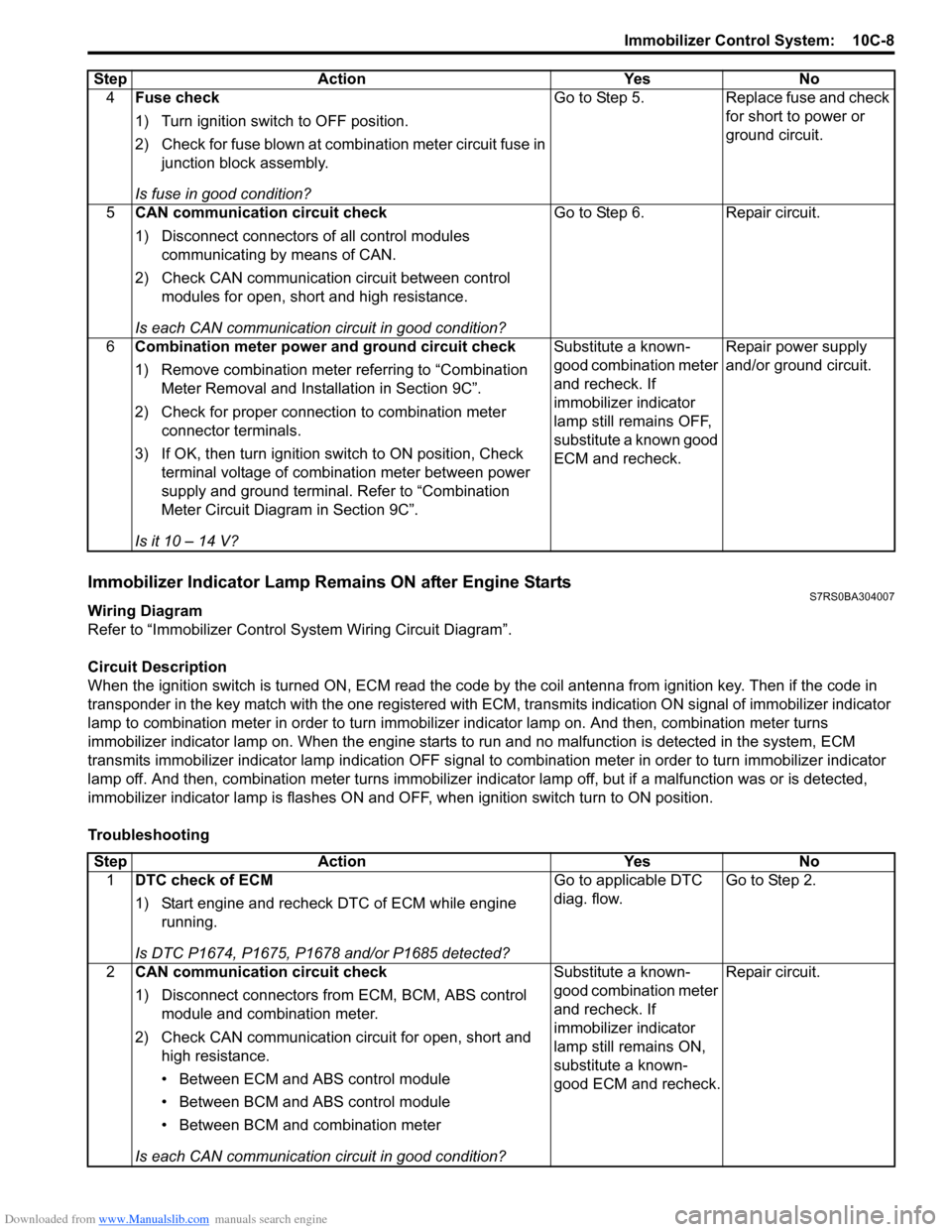
Troubleshooting 4
Fuse check
1) Turn ignition switch to OFF position.
2) Check for fuse blown at combination meter circuit fuse in
junction block assembly.
Is fuse in good condition? Go to Step 5. Replace fuse and check
for short to power or
ground circuit.
5 CAN communication circuit check
1) Disconnect connectors of all control modules
communicating by means of CAN.
2) Check CAN communication circuit between control modules for open, short and high resistance.
Is each CAN communication circuit in good condition? Go to Step 6. Repair circuit.
6 Combination meter power and ground circuit check
1) Remove combination meter referring to “Combination
Meter Removal and Installation in Section 9C”.
2) Check for proper connection to combination meter connector terminals.
3) If OK, then turn ignition switch to ON position, Check terminal voltage of combination meter between power
supply and ground terminal. Refer to “Combination
Meter Circuit Diagram in Section 9C”.
Is it 10 – 14 V? Substitute a known-
good combination meter
and recheck. If
immobilizer indicator
lamp still remains OFF,
substitute a known good
ECM and recheck.
Repair power supply
and/or ground circuit.
Step Action Yes No
Step
Action YesNo
1 DTC check of ECM
1) Start engine and recheck DTC of ECM while engine
running.
Is DTC P1674, P1675, P1678 and/or P1685 detected? Go to applicable DTC
diag. flow.
Go to Step 2.
2 CAN communication circuit check
1) Disconnect connectors from ECM, BCM, ABS control
module and combination meter.
2) Check CAN communication circuit for open, short and high resistance.
• Between ECM and ABS control module
• Between BCM and ABS control module
• Between BCM and combination meter
Is each CAN communication circuit in good condition? Substitute a known-
good combination meter
and recheck. If
immobilizer indicator
lamp still remains ON,
substitute a known-
good ECM and recheck.
Repair circuit.
Page 1452 of 1496
Downloaded from www.Manualslib.com manuals search engine 10C-9 Immobilizer Control System:
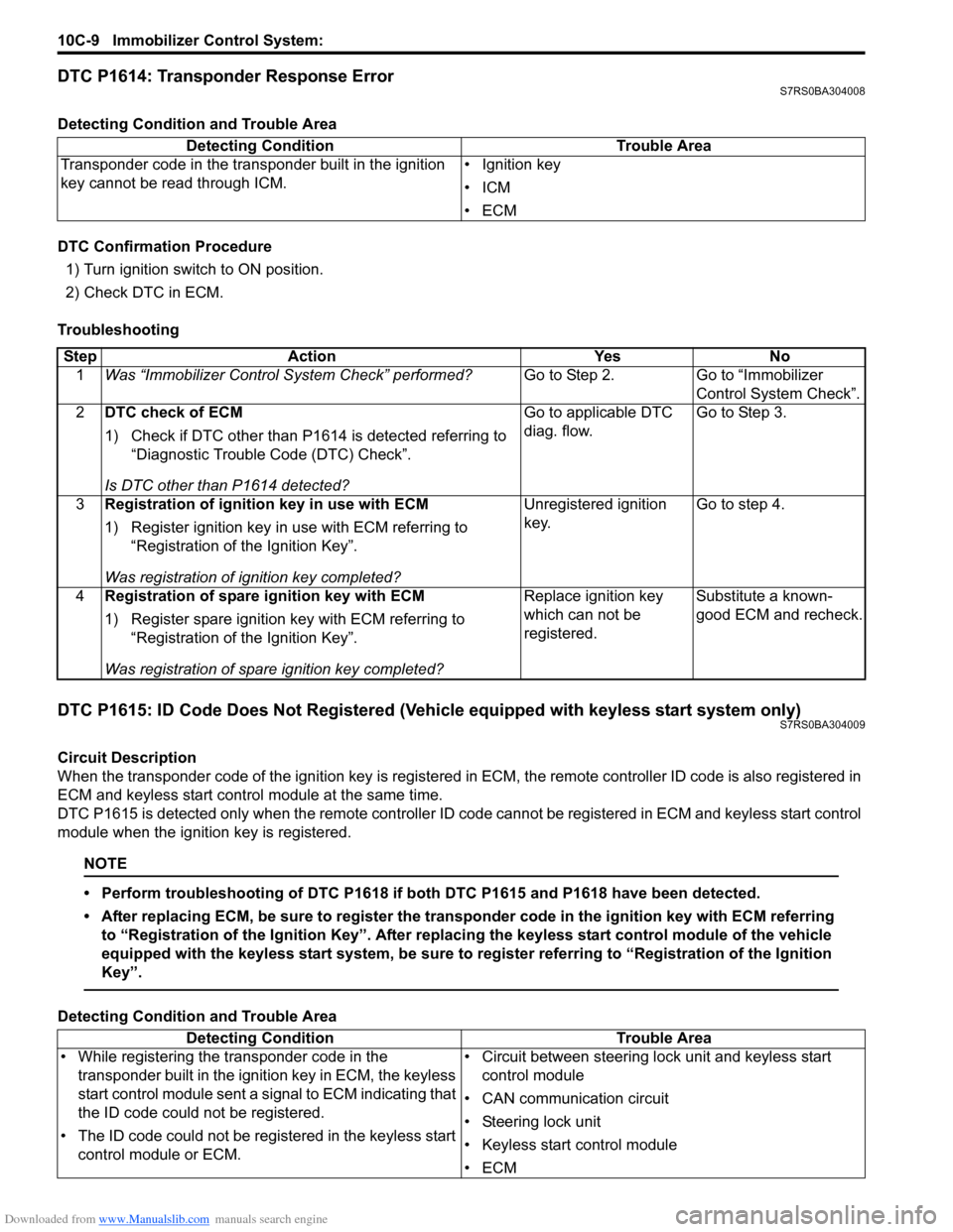
DTC P1614: Transponder Response ErrorS7RS0BA304008
Detecting Condition and Trouble Area
DTC Confirmation Procedure
1) Turn ignition switch to ON position.
2) Check DTC in ECM.
Troubleshooting
DTC P1615: ID Code Does Not Registered (Vehicle equipped with keyless start system only)S7RS0BA304009
Circuit Description
When the transponder code of the ignition key is registered in ECM, the remote controller ID code is also registered in
ECM and keyless start contro l module at the same time.
DTC P1615 is detected only when the remote controller ID code cannot be registered in ECM and keyless start control
module when the ignition key is registered.
NOTE
• Perform troubleshooting of DTC P1618 if both DTC P1615 and P1618 have been detected.
• After replacing ECM, be sure to register the tran sponder code in the ignition key with ECM referring
to “Registration of the Ignition Key”. After replac ing the keyless start control module of the vehicle
equipped with the keyless start system, be sure to register referring to “Registration of the Ignition
Key”.
Detecting Condition and Trouble Area Detecting Condition Trouble Area
Transponder code in the transponder built in the ignition
key cannot be read through ICM. • Ignition key
•ICM
•ECM
Step
Action YesNo
1 Was “Immobilizer Control S ystem Check” performed? Go to Step 2.Go to “Immobilizer
Control System Check”.
2 DTC check of ECM
1) Check if DTC other than P1614 is detected referring to
“Diagnostic Trouble Code (DTC) Check”.
Is DTC other than P1614 detected? Go to applicable DTC
diag. flow.
Go to Step 3.
3 Registration of ignition key in use with ECM
1) Register ignition key in use with ECM referring to
“Registration of the Ignition Key”.
Was registration of ignition key completed? Unregistered ignition
key.
Go to step 4.
4 Registration of spare ignition key with ECM
1) Register spare ignition key with ECM referring to
“Registration of the Ignition Key”.
Was registration of spare ignition key completed? Replace ignition key
which can not be
registered.
Substitute a known-
good ECM and recheck.
Detecting Condition
Trouble Area
• While registering the transponder code in the transponder built in the ignition key in ECM, the keyless
start control module sent a signal to ECM indicating that
the ID code could not be registered.
• The ID code could not be registered in the keyless start control module or ECM. • Circuit between steering lo
ck unit and keyless start
control module
• CAN communication circuit
• Steering lock unit
• Keyless start control module
•ECM
Page 1453 of 1496
Downloaded from www.Manualslib.com manuals search engine Immobilizer Control System: 10C-10
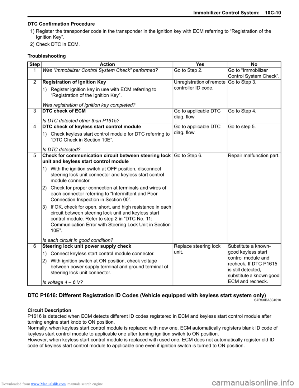
DTC Confirmation Procedure1) Register the transponder code in the transponder in the ignition key with ECM referring to “Registration of the
Ignition Key”.
2) Check DTC in ECM.
Troubleshooting
DTC P1616: Different Registration ID Codes (Vehicle equipped with keyless start system only)S7RS0BA304010
Circuit Description
P1616 is detected when ECM detects different ID codes registered in ECM and keyless start control module after
turning engine start knob to ON position.
Normally, when keyless start control module is replaced with new one, ECM automatically registers blank ID code of
keyless start control module to applicable one after turning ignition switch to ON position.
However, when keyless start control module is replaced wit h used one, ECM does not automatically register old ID
code of keyless start control module to applicable one ev en if ignition switch is turned to ON position.
Step Action Yes No
1 Was “Immobilizer Control S ystem Check” performed? Go to Step 2. Go to “Immobilizer
Control System Check”.
2 Registration of Ignition Key
1) Register ignition key in use with ECM referring to
“Registration of the Ignition Key”.
Was registration of ignition key completed? Unregistration of remote
controller ID code.
Go to Step 3.
3 DTC check of ECM
Is DTC detected other than P1615? Go to applicable DTC
diag. flow.
Go to Step 4.
4 DTC check of keyless start control module
1) Check keyless start control module for DTC referring to
“DTC Check in Section 10E”.
Is DTC detected? Go to applicable DTC
diag. flow.
Go to step 5.
5 Check for communication circuit between steering lock
unit and keyless start control module
1) With the ignition switch at OFF position, disconnect
steering lock unit connector and keyless start control
module connector.
2) Check for proper connection at terminals and wires of
each connector referring to “Intermittent and Poor
Connection Inspection in Section 00”.
3) If OK, check for open, short, and high resistance in each circuit between steering lock unit and keyless start
control module. Refer to step 2 in “DTC No. 11:
Communication Error with Steeri ng Lock Unit in Section
10E”.
Is each circuit in good condition? Go to Step 6. Repair malfunction part.
6 Steering lock unit power supply check
1) Connect keyless start control module connector.
2) With ignition switch at ON position, check voltage
between power supply terminal and ground terminal of
steering lock unit connector.
Is voltage 4 – 6 V? Replace steering lock
unit.
Substitute a known-
good keyless start
control module and
recheck. If DTC P1615
is still detected,
substitute a known good
ECM and recheck.