ECM wiring diagram SUZUKI SWIFT 2008 2.G Service Owners Manual
[x] Cancel search | Manufacturer: SUZUKI, Model Year: 2008, Model line: SWIFT, Model: SUZUKI SWIFT 2008 2.GPages: 1496, PDF Size: 34.44 MB
Page 934 of 1496

Downloaded from www.Manualslib.com manuals search engine 7-ii Table of Contents
Recommended Service Material ....................... 7B-33
Special Tool ...................................................... 7B-33
Automatic Type .................... .................................7B-34
Precautions.........................................................7B-34 A/C System Caution .......................................... 7B-34
Precautions in Diagnosing Trouble ................... 7B-34
Precautions on Servicing A/C System .............. 7B-34
General Description .......... .................................7B-34
Auto A/C System Descript ion ............................ 7B-34
HVAC Control Module Operation Description ... 7B-36
Refrigerant Type Identifica tion .......................... 7B-36
Sub-Cool A/C System Description .................... 7B-36
A/C Operation Description ................................ 7B-36
On-Board Diagnostic System Description ......... 7B-37
Schematic and Routing Diagram ......................7B-37 Major Components of A/C System .................... 7B-37
A/C System Wiring Diagra m ............................. 7B-38
Diagnostic Information and Procedures ..........7B-39 A/C System Symptom Diagnosis ...................... 7B-39
Abnormal Noise Sympto m Diagnosis of A/C
System ............................................................ 7B-42
DTC Check........................................................ 7B-42
DTC Clearance ................................................. 7B-43
DTC Table ......................................................... 7B-44
Fail-Safe Table ................. ................................. 7B-45
Scan Tool Data ................................................. 7B-46
Air Conditioning System Check......................... 7B-47
Visual Inspection ............................................... 7B-49
DTC B1502: Inside Air Temperature Sensor and/or Its Circuit Malfunction .......................... 7B-49
DTC B1503: A/C Evaporator Air Temperature Sensor and/or Its Circuit Malfunction .............. 7B-50
DTC B1504: Sunload Sensor and/or Its Circuit Malfunction ......... ................................. 7B-52
DTC B1511: Temperature Control Actuator (Position Sensor) and/or Its Circuit
Malfunction ...................................................... 7B-53
DTC B1512: Air flow Control Actuator (Position Sensor) and/or Its Circuit
Malfunction ...................................................... 7B-55
DTC B1513: Temperature Control Actuator and/or Its Circuit Malfunction .......................... 7B-57
DTC B1514: Air Flow Co ntrol Actuator and/or
Its Circuit Malfunction ...................................... 7B-60
DTC B1541: HVAC Control Module Back-Up Power Supply Malfunction .............................. 7B-62
DTC B1546: A/C Refrigerant Pressure Malfunction ...................................................... 7B-63
DTC B1551: Serial Communication Circuit Malfunction ...................................................... 7B-63
DTC B1552: Serial Communication Signal Malfunction ...................................................... 7B-64
DTC B1553: CAN Communication Signal Malfunction ...................................................... 7B-65
DTC B1557: Vehicle Speed Sensor Signal Malfunction ...................................................... 7B-65
DTC B1561: Engine Coolant Temperature Sensor Signal Malfunctio n .............................. 7B-66 DTC B1562: Outside Air Temperature Sensor
Signal Malfunction ........................................... 7B-66
DTC B1563: A/C Refr igerant Pressure
Sensor Signal Malfunction .............................. 7B-66
Inspection of HVAC Control Module and Its Circuit .............................................................. 7B-67
A/C System Performance Inspection ................ 7B-70
A/C System Inspection at ECM ......................... 7B-70
Repair Instructions ............ ................................7B-71
Operation Procedure for Refrigerant Charge .... 7B-71
HVAC Unit Components ................................... 7B-72
HVAC Unit Removal and In stallation ................ 7B-73
Temperature Control Actuator Removal and Installation ....................................................... 7B-73
Temperature Control Actuat or Inspection ......... 7B-73
Air Flow Control Actuator Removal and Installation ....................................................... 7B-74
Air Flow Control Actuator Inspection ................. 7B-74
Air Intake Control Actuator Removal and Installation ....................................................... 7B-75
Air Intake Control Actuator Inspection............... 7B-75
Actuator Linkage Inspection .............................. 7B-76
Blower Motor Controller Removal and Installation ....................................................... 7B-76
Blower Motor Controller Inspection ................... 7B-76
HVAC Control Module Removal and Installation ....................................................... 7B-77
Sunload Sensor Removal and Installation ........ 7B-77
Sunload Sensor Inspection ............................... 7B-77
Outside Air Temperature Sensor Removal and Installation ................................................ 7B-77
Outside Air Temperature Sensor Inspection ..... 7B-77
Inside Air Temperature Sensor Removal and Installation ....................................................... 7B-78
Inside Air Temperature Sens or Inspection ........ 7B-78
Condenser Assembly On-Vehicle Inspection .... 7B-78
Condenser Assembly Removal and Installation ....................................................... 7B-78
Receiver/Dryer Removal and Installation .......... 7B-78
Evaporator Inspection ....................................... 7B-78
Evaporator Temperature Sensor Removal and Installation ................................................ 7B-78
Evaporator Temperature Se nsor Inspection ..... 7B-78
Expansion Valve Removal an d Installation ....... 7B-78
Expansion Valve Inspection .............................. 7B-78
A/C Refrigerant Pressure Sensor and Its Circuit Inspection............................................. 7B-78
A/C Refrigerant Pressu re Sensor Removal
and Installation ................................................ 7B-78
Compressor Relay Inspection .
.......................... 7B-78
Compressor Drive Belt Inspection and Adjustment ...................................................... 7B-78
Compressor Drive Belt Removal and Installation ....................................................... 7B-79
Compressor Assembly Removal and Installation ....................................................... 7B-79
Compressor Assembly Components................. 7B-79
Magnet Clutch Removal and Installation........... 7B-79
Magnet Clutch Inspection.................................. 7B-79
Relief Valve Inspection...................................... 7B-79
Page 938 of 1496
Downloaded from www.Manualslib.com manuals search engine 7A-2 Heater and Ventilation:
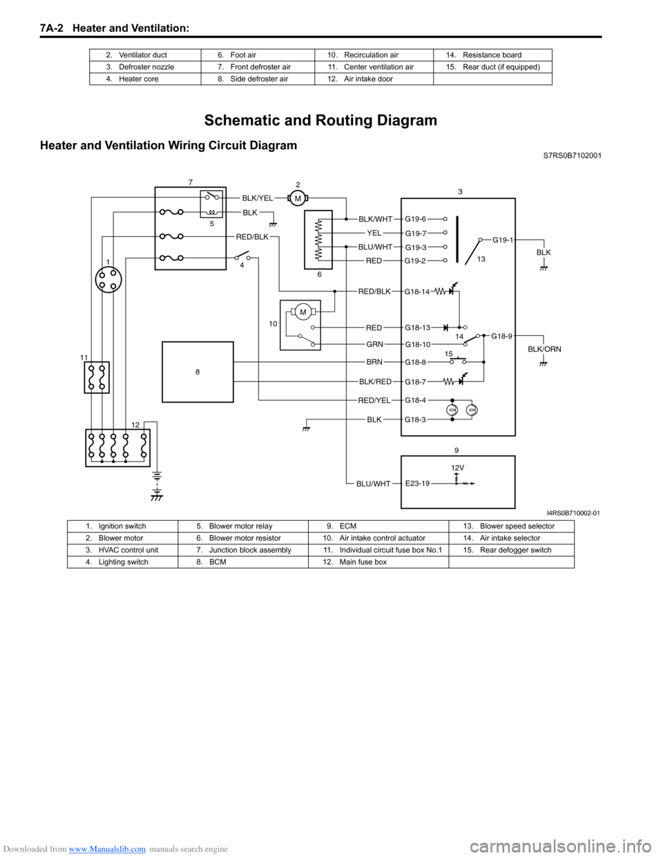
Schematic and Routing Diagram
Heater and Ventilation Wiring Circuit DiagramS7RS0B7102001
2. Ventilator duct 6. Foot air 10. Recirculation air 14. Resistance board
3. Defroster nozzle 7. Front defroster air 11. Center ventilation air 15. Rear duct (if equipped)
4. Heater core 8. Side defroster air 12. Air intake door
BLK
RED/BLK
3
5
7
BLK
2
M
12V
BLU/WHTE23-19
G18-3
G18-4
G18-7
G18-8
G18-10
G18-13
G19-2
G19-3
G19-7
G19-6
G19-1
G18-9
G18-14
BLK/WHT
YEL
BLU/WHT
RED
RED/BLK
RED
GRN
BRN
BLK/RED
RED/YEL
BLK
BLK/YEL
BLK/ORN
4
6
10
8
9
M1
12
11 13
14
15
I4RS0B710002-01
1. Ignition switch 5. Blower motor relay 9. ECM 13. Blower speed selector
2. Blower motor 6. Blower motor resistor 10. Air intake control actuator 14. Air intake selector
3. HVAC control unit 7. Junction block assembly 11. Ind ividual circuit fuse box No.1 15. Rear defogger switch
4. Lighting switch 8. BCM 12. Main fuse box
Page 954 of 1496
Downloaded from www.Manualslib.com manuals search engine 7B-6 Air Conditioning System: Manual Type
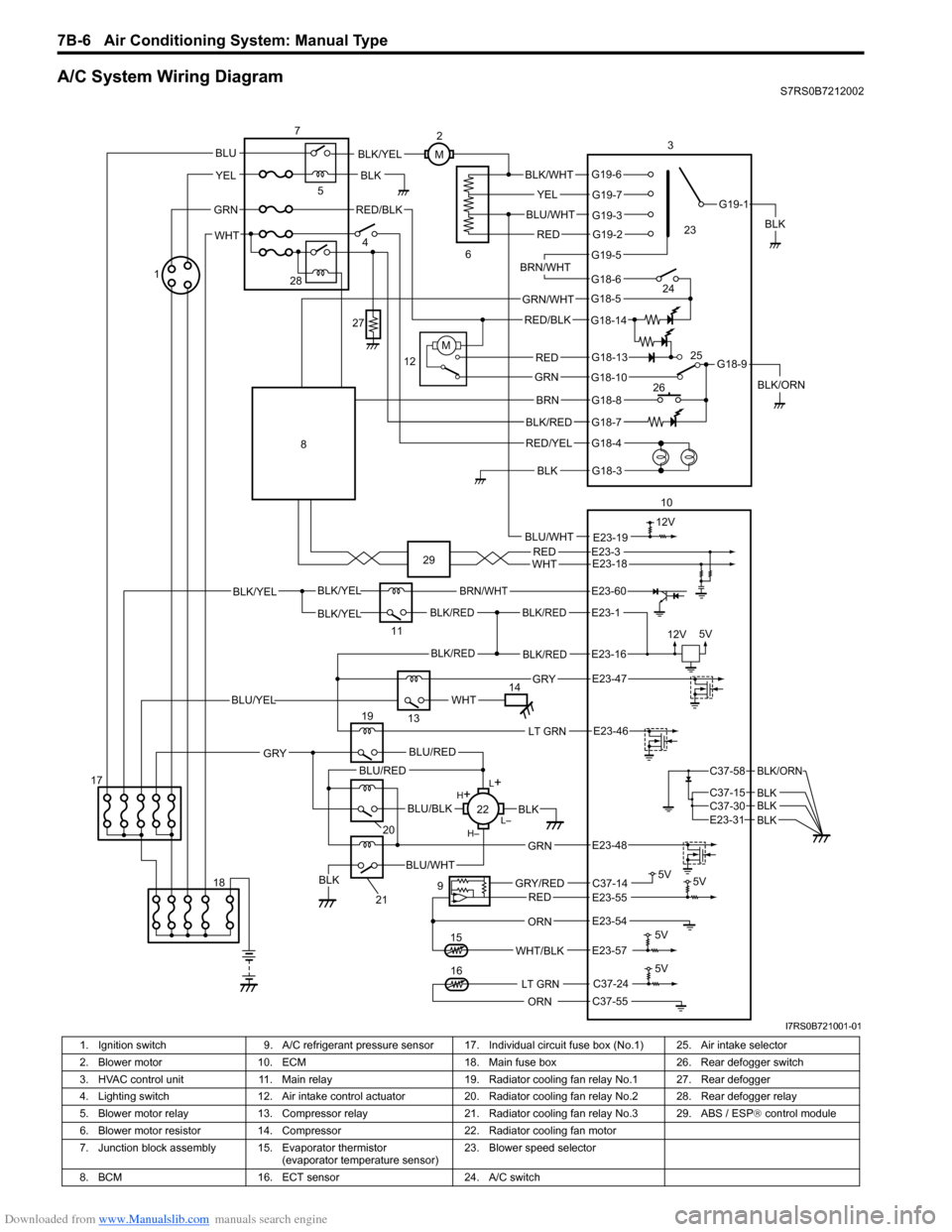
A/C System Wiring DiagramS7RS0B7212002
BLK/REDBLK/RED
BLK/YELBLK/YEL
BLK/YEL
BRN/WHT
12V5V
5V 5V
5V11
E23-1
E23-60
BLK/REDBLK/REDE23-16
E23-57WHT/BLK
9
13
E23-55C37-14GRY/REDRED
BLK
ORN
E23-47 GRY
WHTBLU/YEL
RED/BLK
14 3
1
15
5
7
BLK
2
M
12VBLU/WHTE23-19
C37-24
C37-55ORN
5V
LT GRN16
G18-3
G18-4
G18-7
G18-8
G18-10
G18-13
G18-5
G18-6
G19-5
G19-2
G19-3
G19-7
G19-6
G19-1
G18-9
G18-14
BLK/WHT
YEL
BLU/WHT
RED
BRN/WHT
GRN/WHT
RED/BLK
RED
GRN
BRN
BLK/RED
RED/YEL
BLK
BLK/YEL
BLK/ORN
4
6
12
10
M
E23-54
REDWHTE23-3E23-18
17 18
LT GRNE23-46
L+
L–
H–
H
+
BLU/RED
BLK
BLU/WHTBLK
BLU/BLK
20
GRN
GRY
E23-48
19
21
22
BLU/REDC37-58
C37-15 C37-30
BLK/ORN
BLKBLKE23-31 BLK
BLU
YEL
GRN
WHT
23
24
26 25
28
27
8
29
I7RS0B721001-01
1. Ignition switch
9. A/C refrigerant pressure sensor 17. I ndividual circuit fuse box (No.1) 25. Air intake selector
2. Blower motor 10. ECM 18. Main fuse box 26. Rear defogger switch
3. HVAC control unit 11. Main relay 19. Radiator cooling fan relay No.1 27. Rear defogger
4. Lighting switch 12. Air intake control actuator 20. Radiator cooling fan relay No.2 28. Rear defogger relay
5. Blower motor relay 13. Compressor relay 21. Radiator cooling fan relay No.3 29. ABS / ESP ® control module
6. Blower motor resistor 14. Compressor 22. Radiator cooling fan motor
7. Junction block assembly 15. Evaporator thermistor (evaporator temperature sensor)23. Blower speed selector
8. BCM 16. ECT sensor 24. A/C switch
Page 1217 of 1496
Downloaded from www.Manualslib.com manuals search engine Wiring Systems: 9A-46
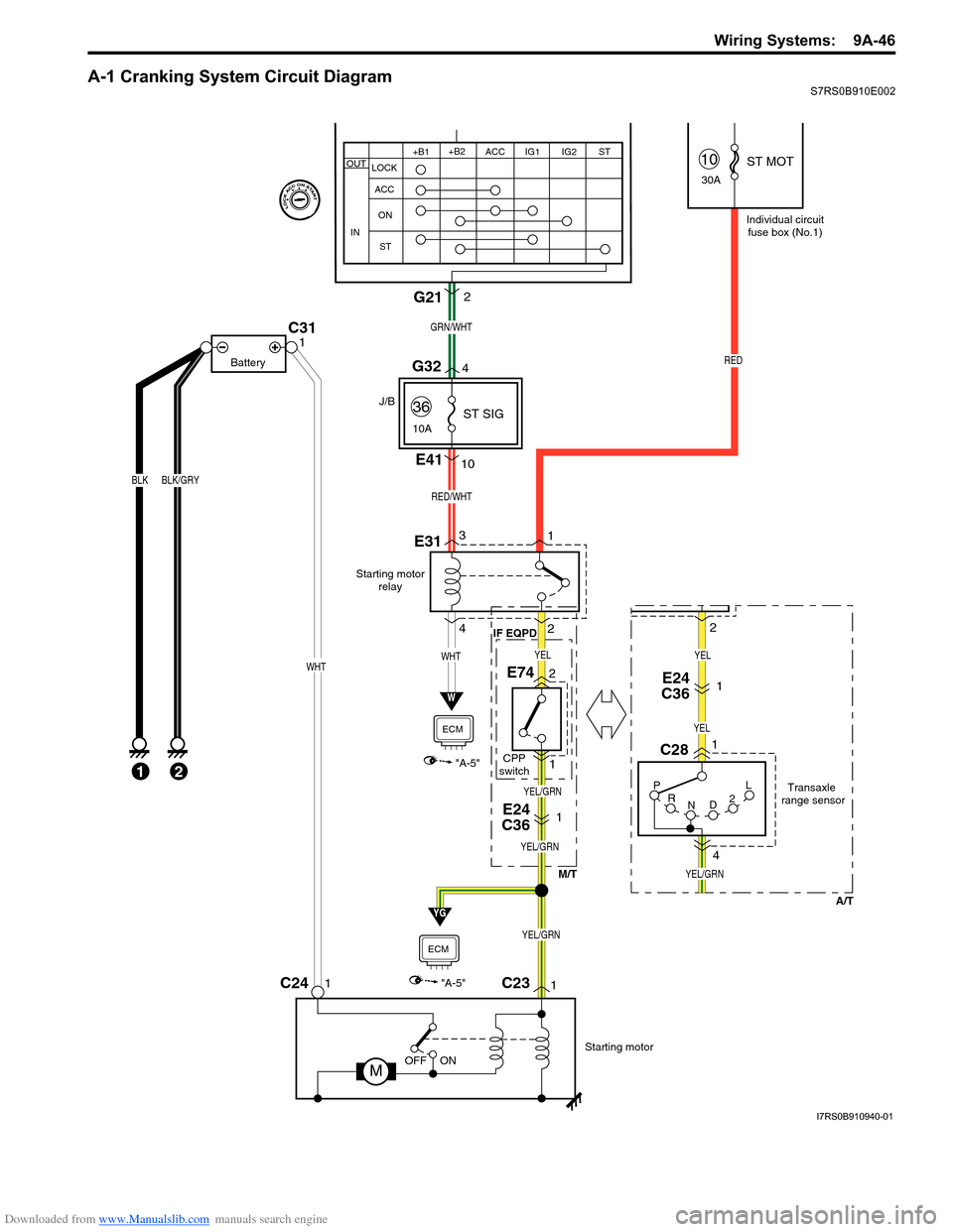
A-1 Cranking System Circuit DiagramS7RS0B910E002
Starting motorrelay
W
"A-5"
ECM
P
R N D2LTransaxle
range sensor
C28
E741
4
E31
C231C241
Starting motor
MOFF ON
BLK
1
BLK/GRY
C311
Battery
E24
C361
RED
Individual circuit
fuse box (No.1)
10
30A
36
10A
WHTWHT
M/T
IF EQPD
E24
C361
J/B
A/T
E4110
13
2
4
RED/WHT
2 ST MOT
ST SIG
YEL/GRN
YG
"A-5"
ECM
GRN/WHT
G212
YEL/GRN
YEL/GRN
YEL
YEL/GRN
YEL
YEL
G324
+B1
LOCK
ACC
ON
ST ACC IG1 IG2
STOUT
IN
+B2
21CPP
switch
2
I7RS0B910940-01
Page 1218 of 1496
Downloaded from www.Manualslib.com manuals search engine 9A-47 Wiring Systems:
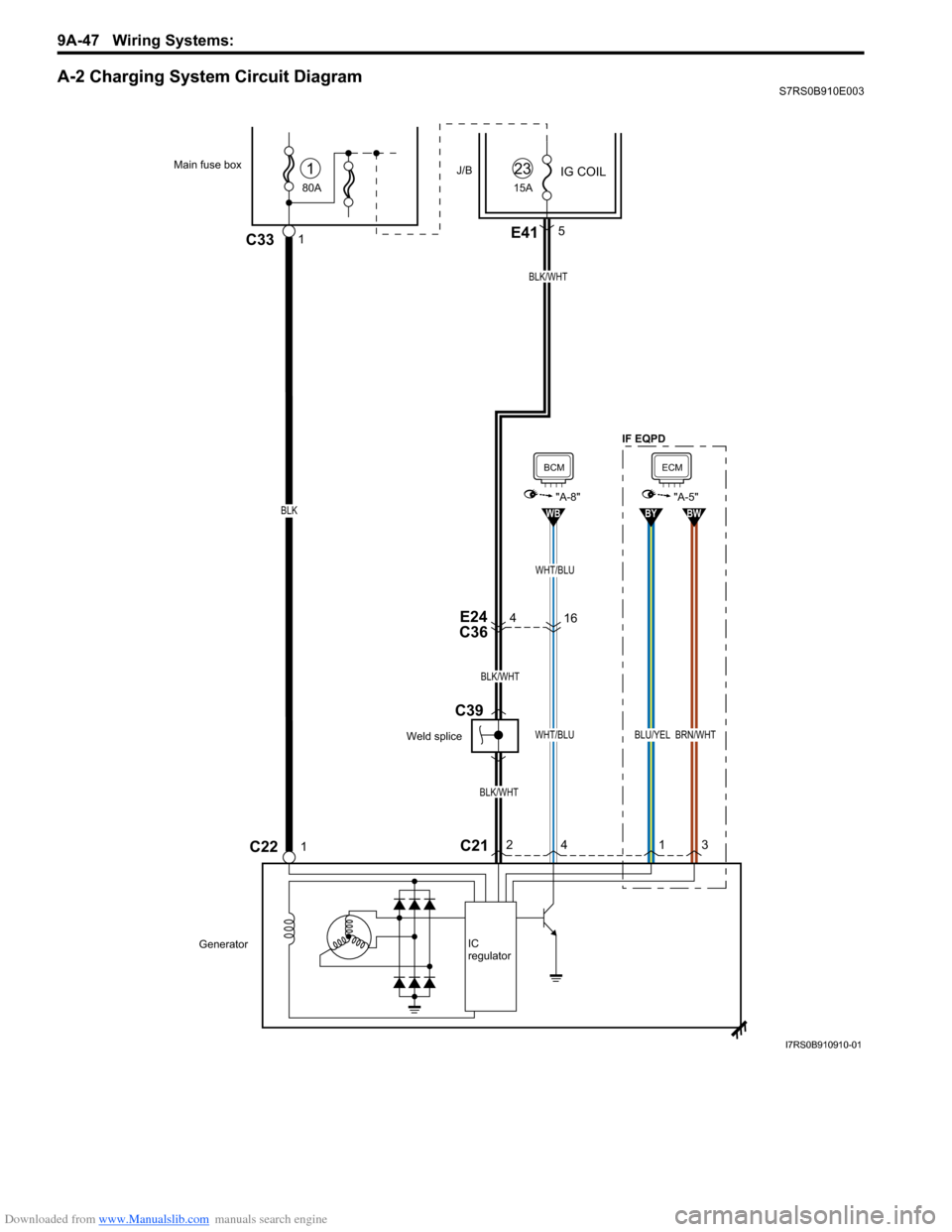
A-2 Charging System Circuit DiagramS7RS0B910E003
4E24
C36
BLK/WHT
BLK/WHT
BLK/WHT
80A
Main fuse box
C22
J/B
1C33
IG COIL1
15A
23
GeneratorIC
regulator
1
E415
C212
4
WHT/BLU
WB
BCM
"A-8"
1
BLU/YEL
BY
3
BRN/WHT
BW
ECM
"A-5"
16
WHT/BLU
BLK
Weld splice
C39
IF EQPD
I7RS0B910910-01
Page 1219 of 1496
Downloaded from www.Manualslib.com manuals search engine Wiring Systems: 9A-48
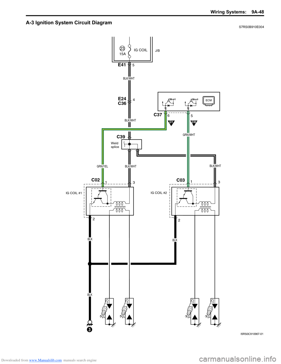
A-3 Ignition System Circuit DiagramS7RS0B910E004
15A
4E24
C36
2
C021 3
IG COIL #1
C03
BLK
BLK/WHTGRN/YEL
BLK/WHT
J/B
ECM
GYGW
23IG COIL
BLK
BLK
IG COIL #2
E415
3
GRN/WHT
1
3
2
C375
6
Weld
splice
C39
BLK/WHT
BLK/WHT
I5RS0C910967-01
Page 1220 of 1496

Downloaded from www.Manualslib.com manuals search engine 9A-49 Wiring Systems:
A-4 Cooling System Circuit DiagramS7RS0B910E005
E17
M
21
2
1
7
"A-5"
LT GRN
"A-5"
Lg
BRN/WHT
BW
BLK/YELBLK/YEL
BR
Relay #1
E283
5
BLU/RED
Relay #2
E29
3
2
1
Relay #3
E305 312
4 3
GRY
GRN
BLU/RED
BLU/WHT
BLU/REDBLU/REDBLU/BLK
GRN
GRY
30ARDTR
FAN
14
E324
3
15A FI
5
2
1
5
Main relay
BLK
BLK
Weld
splice
E55
BLK/RED
BLK/RED
ECM
ECM
Individual circuit fuse box (No.1)
G
I7RS0B910911-01
Page 1221 of 1496
Downloaded from www.Manualslib.com manuals search engine Wiring Systems: 9A-50
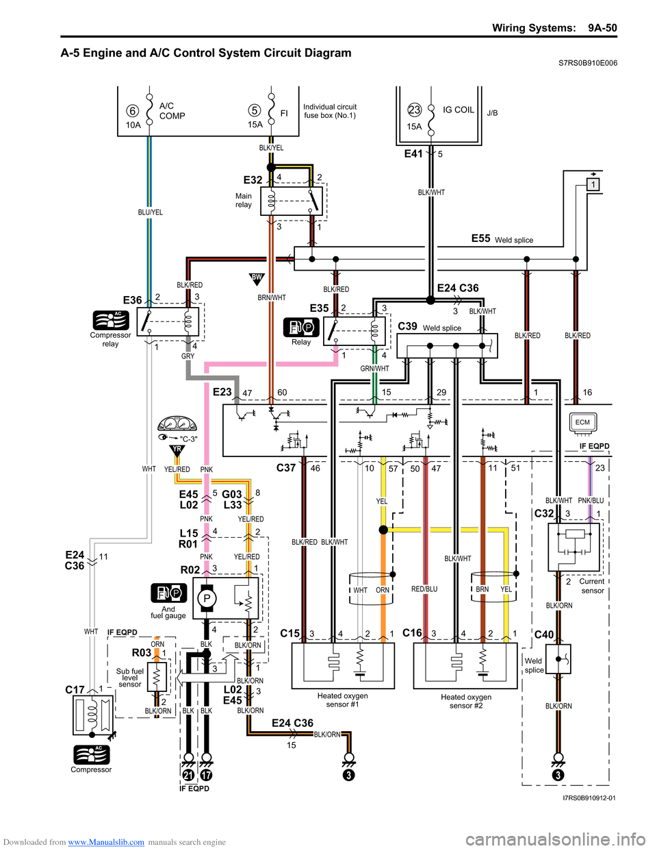
A-5 Engine and A/C Control System Circuit DiagramS7RS0B910E006
YEL/RED
E45L02 G03
L33
L02
E4558
L15
R0142
PNKYEL/RED
P
PNKYEL/RED
31
3
3 1
E24 C36
BLK/ORN
BLK/ORN
BLK/ORN
BLK/ORN
3
15
BLK
42
R02
1
2
R03
And
fuel gauge
Sub fuel level
sensor
Main
relay
1BLK/WHT
BLK/WHT
C39Weld splice Weld splice
E55
GRN/WHT
IG COILJ/B5
15A
FI
BLK/YEL
E324
32
1 15A
23
BRN/WHT
BW
YR
6
10A
A/C
COMP
Compressor
relay
E36
Relay
BLU/YEL
Compressor
C171
E415
E24 C36
3
E24
C3611
BLK/WHT
C15 C16
Heated oxygen
sensor #1
BLK/RED
WHT
Heated oxygensensor #2
BRN
BLK/WHT
RED/BLU
C37
34213421
4610574711
YEL
5123PNK
ECM
41 3
2
WHT
WHT
BLK/REDBLK/RED
BLK/RED
E23476015291
GRY
E3523
1
4
ORN
BLKBLKBLK/ORN
ORN
YEL
50
BLK/RED
16
17213
Individual circuit
fuse box (No.1)
BLK/ORN
BLK/ORN
BLK/WHTPNK/BLU
IF EQPD
IF EQPD IF EQPD
Weld
splice
C40 C32
Current
sensor
3
2 1
"C-3"
I7RS0B910912-01
Page 1228 of 1496
Downloaded from www.Manualslib.com manuals search engine 9A-57 Wiring Systems:
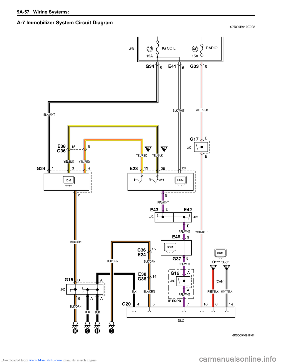
A-7 Immobilizer System Circuit DiagramS7RS0B910E008
ECMICM
DLC
G204
10
J/C
G15
5
5
7
113
IG COIL
G346
J/B
29
15A
23
BLK/WHT
13 28
YEL/BLK
YBYR
E38
G3614
C36 E2415
BLK/ORN
BLK/ORN
BLK/ORN
BLK
J/C
E43
J/C
G16
BCM
G375
E469
16
WHT/RED
E233G241 4
BLK/ORN
2
E38
G36515
G335
15A RADIO
40
E415
YEL/REDYEL/BLK
WHT/REDBLK/WHT
J/C
G17
PPL/WHT
PPL/WHT
PPL/WHT
D
E
PPL/WHT
A
A B
B
A A
B
B
YEL/RED
9
A
BLK/ORN
BLKBLK
WHT/BLKRED/BLK
RBWB"A-8"
14
6
BCM
E42
J/C
IF EQPD (CAN)
I6RS0C910917-01
Page 1229 of 1496
Downloaded from www.Manualslib.com manuals search engine Wiring Systems: 9A-58
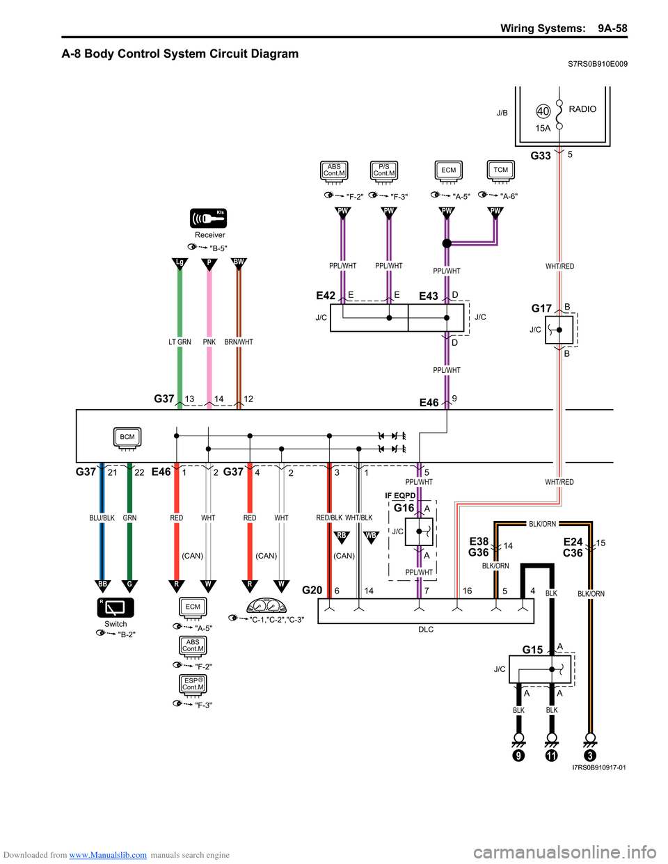
A-8 Body Control System Circuit DiagramS7RS0B910E009
1E462
WHTRED
4G372
WHTRED
3
G20
1
6 14
WHT/BLKRED/BLK
PNKLT GRN
G37
DLC
4
11
BLK
BLK
A
A
J/C
G15
13 1412
Receiver
5PPL/WHTWHT/RED
PPL/WHT
A
A
J/C
G16
"A-5""F-2""F-3"
9E46
PPL/WHT
ECM
E
D
J/C
EDE43
PPL/WHTPPL/WHT
P/S
Cont.MABS
Cont.M
E42
RW
PW
PPL/WHT
PWPWPW
"A-6"
TCM
E38
G3614E24
C3615
BLK/ORN
5
3
J/B
15A RADIO
40
G335
WHT/RED
BLK/ORN
716
B
B
J/C
G17
BLK/ORN
"C-1,"C-2","C-3"
"B-2"
Switch
21G3722
GRNBLU/BLK
BBG
BWPLg
"B-5"
RW
"A-5"
J/C
9
BLK
A
RBWB
ECM
"F-2"
ABS
Cont.M
"F-3"
ESP
Cont.M
BCM
BRN/WHT
IF EQPD
(CAN) (CAN) (CAN)
R
I7RS0B910917-01