Hose SUZUKI SWIFT 2008 2.G Service Workshop Manual
[x] Cancel search | Manufacturer: SUZUKI, Model Year: 2008, Model line: SWIFT, Model: SUZUKI SWIFT 2008 2.GPages: 1496, PDF Size: 34.44 MB
Page 516 of 1496
Downloaded from www.Manualslib.com manuals search engine 4A-18 Brake Control System and Diagnosis:
10) Check pedal height and play referring to “Brake Pedal Free Height Inspection” and “Brake Pedal
Play Inspection”.
11) Check each installed part for fluid leakage and perform brake test.
12) Evacuate and charge refrigerant by referring to “Evacuating of A/C Syst em” and “Procedure of
Charging” under “Operation Procedure for
Refrigerant Charge in Section 7B” or “Operation
Procedure for Refrigerant Charge in Section 7B”.
Brake Booster Inspection and AdjustmentS7RS0B4106018
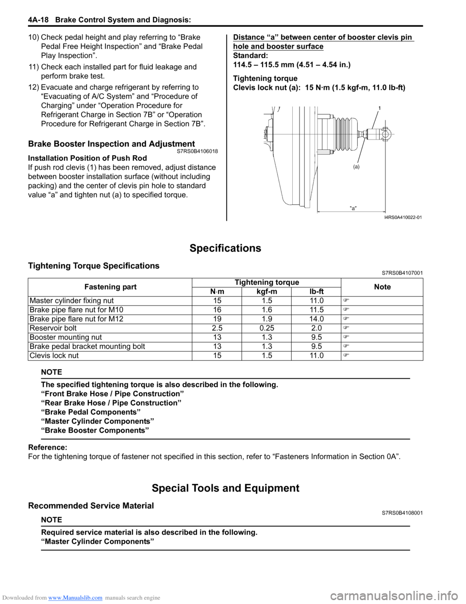
Installation Position of Push Rod
If push rod clevis (1) has b een removed, adjust distance
between booster installation surface (without including
packing) and the center of clevis pin hole to standard
value “a” and tighten nut (a) to specified torque. Distance “a” between center of booster clevis pin
hole and booster surface
Standard:
114.5 – 115.5 mm (4.51 – 4.54 in.)
Tightening torque
Clevis lock nut (a): 15 N·m (1.5 kgf-m, 11.0 lb-ft)
Specifications
Tightening Torque SpecificationsS7RS0B4107001
NOTE
The specified tightening torque is also described in the following.
“Front Brake Hose / Pipe Construction”
“Rear Brake Hose / Pipe Construction”
“Brake Pedal Components”
“Master Cylinder Components”
“Brake Booster Components”
Reference:
For the tightening torque of fastener not specified in this
section, refer to “Fasteners Information in Section 0A”.
Special Tools and Equipment
Recommended Service MaterialS7RS0B4108001
NOTE
Required service material is also described in the following.
“Master Cylinder Components”
I4RS0A410022-01
Fastening part Tightening torque
Note
N ⋅mkgf-mlb-ft
Master cylinder fixing nut 15 1.5 11.0 �)
Brake pipe flare nut for M10 16 1.6 11.5 �)
Brake pipe flare nut for M12 19 1.9 14.0 �)
Reservoir bolt 2.5 0.25 2.0 �)
Booster mounting nut 13 1.3 9.5 �)
Brake pedal bracket mounting bolt 13 1.3 9.5 �)
Clevis lock nut 15 1.5 11.0 �)
Page 517 of 1496
Downloaded from www.Manualslib.com manuals search engine Front Brakes: 4B-1
Brakes
Front Brakes
Repair Instructions
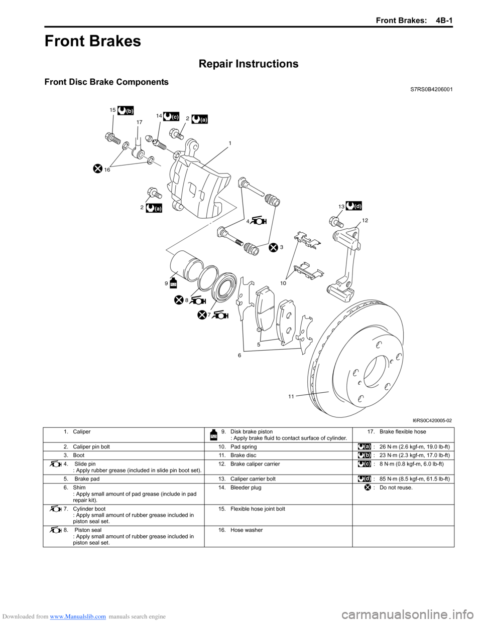
Front Disc Brake ComponentsS7RS0B4206001
11
5
6
10
4
1
16
17
12
8
7
3
2(a)
15
(b)
14(c)2(a)
13
(d)
9
FLD
I6RS0C420005-02
1. Caliper 9. Disk brake piston
: Apply brake fluid to contact surface of cylinder. 17. Brake flexible hose
2. Caliper pin bolt 10. Pad spring : 26 N⋅m (2.6 kgf-m, 19.0 lb-ft)
3. Boot 11. Brake disc: 23 N⋅m (2.3 kgf-m, 17.0 lb-ft)
4. Slide pin : Apply rubber grease (included in slide pin boot set). 12. Brake caliper carrier
: 8 N⋅m (0.8 kgf-m, 6.0 lb-ft)
5. Brake pad 13. Caliper carrier bolt : 85 N⋅m (8.5 kgf-m, 61.5 lb-ft)
6. Shim : Apply small amount of pad grease (include in pad
repair kit). 14. Bleeder plug
: Do not reuse.
7. Cylinder boot : Apply small amount of rubber grease included in
piston seal set. 15. Flexible hose joint bolt
8. Piston seal : Apply small amount of rubber grease included in
piston seal set. 16. Hose washer
Page 518 of 1496
Downloaded from www.Manualslib.com manuals search engine 4B-2 Front Brakes:
Front Disc Brake Pad On-Vehicle InspectionS7RS0B4206002
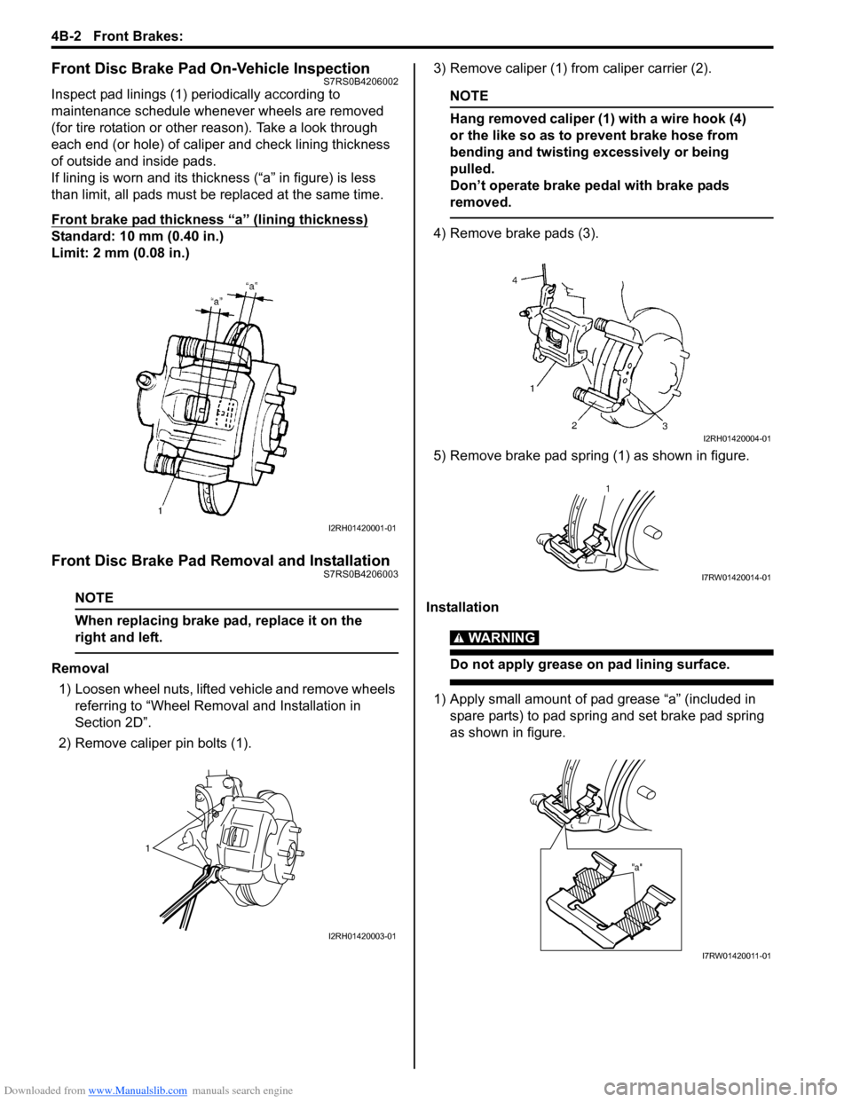
Inspect pad linings (1) periodically according to
maintenance schedule whenever wheels are removed
(for tire rotation or other reason). Take a look through
each end (or hole) of caliper and check lining thickness
of outside and inside pads.
If lining is worn and its thic kness (“a” in figure) is less
than limit, all pads must be replaced at the same time.
Front brake pad thickness “a” (lining thickness)
Standard: 10 mm (0.40 in.)
Limit: 2 mm (0.08 in.)
Front Disc Brake Pad Removal and InstallationS7RS0B4206003
NOTE
When replacing brake pad, replace it on the
right and left.
Removal
1) Loosen wheel nuts, lifted vehicle and remove wheels referring to “Wheel Remova l and Installation in
Section 2D”.
2) Remove caliper pin bolts (1). 3) Remove caliper (1) from caliper carrier (2).
NOTE
Hang removed caliper (1) with a wire hook (4)
or the like so as to prevent brake hose from
bending and twisting excessively or being
pulled.
Don’t operate brake pedal with brake pads
removed.
4) Remove brake pads (3).
5) Remove brake pad spring (1) as shown in figure.
Installation
WARNING!
Do not apply grease on pad lining surface.
1) Apply small amount of pad grease “a” (included in spare parts) to pad spring and set brake pad spring
as shown in figure.
I2RH01420001-01
1
I2RH01420003-01
I2RH01420004-01
1
I7RW01420014-01
"a"
I7RW01420011-01
Page 519 of 1496
Downloaded from www.Manualslib.com manuals search engine Front Brakes: 4B-3
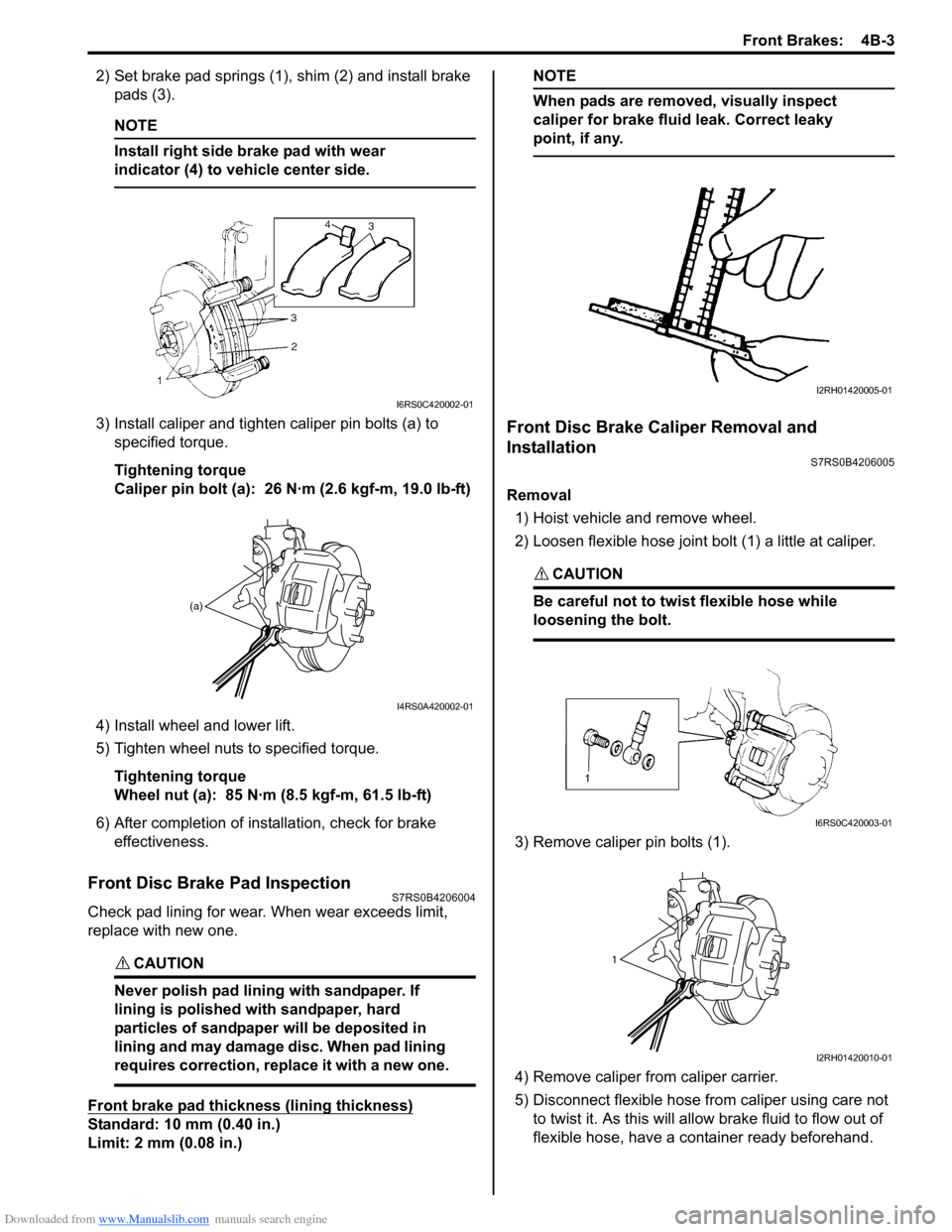
2) Set brake pad springs (1), shim (2) and install brake pads (3).
NOTE
Install right side brake pad with wear
indicator (4) to vehicle center side.
3) Install caliper and tighten caliper pin bolts (a) to specified torque.
Tightening torque
Caliper pin bolt (a): 26 N·m (2.6 kgf-m, 19.0 lb-ft)
4) Install wheel and lower lift.
5) Tighten wheel nuts to specified torque. Tightening torque
Wheel nut (a): 85 N·m (8.5 kgf-m, 61.5 lb-ft)
6) After completion of installation, check for brake effectiveness.
Front Disc Brake Pad InspectionS7RS0B4206004
Check pad lining for wear. When wear exceeds limit,
replace with new one.
CAUTION!
Never polish pad lining with sandpaper. If
lining is polished with sandpaper, hard
particles of sandpaper will be deposited in
lining and may damage disc. When pad lining
requires correction, replace it with a new one.
Front brake pad thickness (lining thickness)
Standard: 10 mm (0.40 in.)
Limit: 2 mm (0.08 in.)
NOTE
When pads are removed, visually inspect
caliper for brake fluid leak. Correct leaky
point, if any.
Front Disc Brake Caliper Removal and
Installation
S7RS0B4206005
Removal
1) Hoist vehicle and remove wheel.
2) Loosen flexible hose joint bolt (1) a little at caliper.
CAUTION!
Be careful not to twist flexible hose while
loosening the bolt.
3) Remove caliper pin bolts (1).
4) Remove caliper fr om caliper carrier.
5) Disconnect flexible hose fr om caliper using care not
to twist it. As this will allow brake fluid to flow out of
flexible hose, have a container ready beforehand.
I6RS0C420002-01
(a)
I4RS0A420002-01
I2RH01420005-01
I6RS0C420003-01
1
I2RH01420010-01
Page 520 of 1496
Downloaded from www.Manualslib.com manuals search engine 4B-4 Front Brakes:
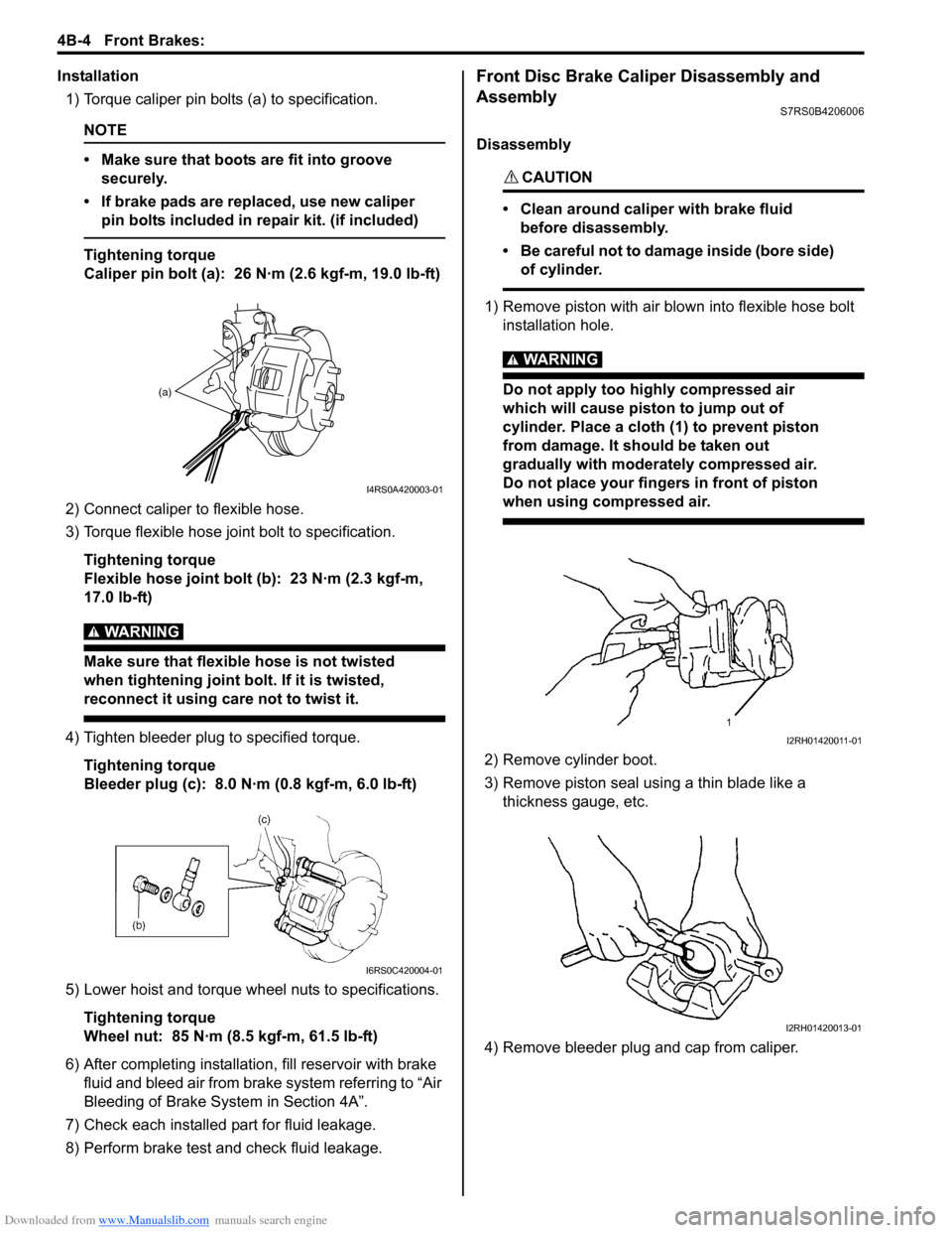
Installation1) Torque caliper pin bolts (a) to specification.
NOTE
• Make sure that boots are fit into groove securely.
• If brake pads are replaced, use new caliper pin bolts included in repair kit. (if included)
Tightening torque
Caliper pin bolt (a): 26 N·m (2.6 kgf-m, 19.0 lb-ft)
2) Connect caliper to flexible hose.
3) Torque flexible hose jo int bolt to specification.
Tightening torque
Flexible hose joint bolt (b): 23 N·m (2.3 kgf-m,
17.0 lb-ft)
WARNING!
Make sure that flexible hose is not twisted
when tightening joint bolt. If it is twisted,
reconnect it using care not to twist it.
4) Tighten bleeder plug to specified torque. Tightening torque
Bleeder plug (c): 8.0 N·m (0.8 kgf-m, 6.0 lb-ft)
5) Lower hoist and torque wheel nuts to specifications. Tightening torque
Wheel nut: 85 N·m (8.5 kgf-m, 61.5 lb-ft)
6) After completing installation, fill reservoir with brake
fluid and bleed air from brake system referring to “Air
Bleeding of Brake System in Section 4A”.
7) Check each installed part for fluid leakage.
8) Perform brake test and check fluid leakage.
Front Disc Brake Caliper Disassembly and
Assembly
S7RS0B4206006
Disassembly
CAUTION!
• Clean around caliper with brake fluid before disassembly.
• Be careful not to damage inside (bore side) of cylinder.
1) Remove piston with air blown into flexible hose bolt installation hole.
WARNING!
Do not apply too highly compressed air
which will cause piston to jump out of
cylinder. Place a cloth (1) to prevent piston
from damage. It should be taken out
gradually with moderately compressed air.
Do not place your fingers in front of piston
when using compressed air.
2) Remove cylinder boot.
3) Remove piston seal using a thin blade like a thickness gauge, etc.
4) Remove bleeder plug and cap from caliper.
(a)
I4RS0A420003-01
I6RS0C420004-01
I2RH01420011-01
I2RH01420013-01
Page 522 of 1496
Downloaded from www.Manualslib.com manuals search engine 4B-6 Front Brakes:
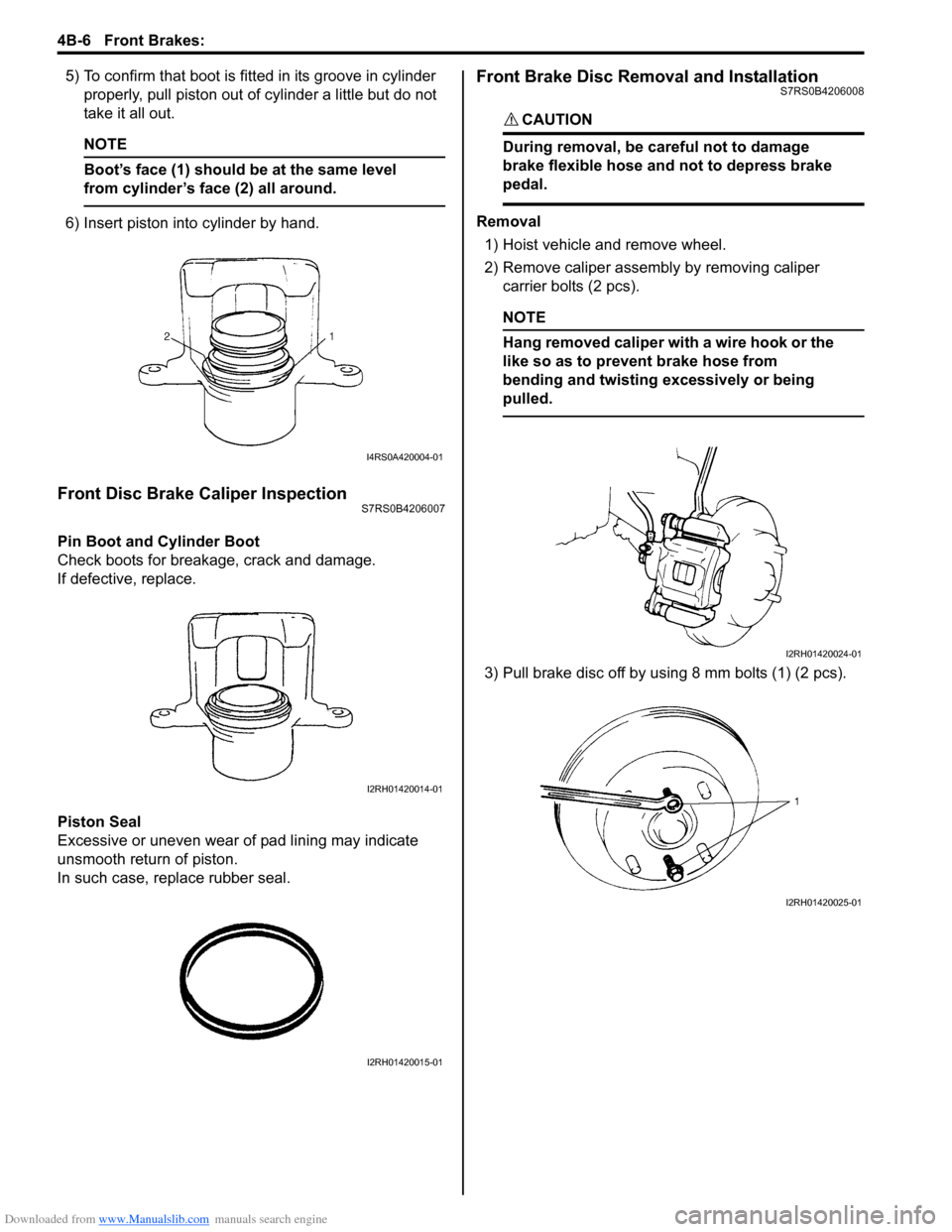
5) To confirm that boot is fitted in its groove in cylinder
properly, pull piston out of cylinder a little but do not
take it all out.
NOTE
Boot’s face (1) should be at the same level
from cylinder’s face (2) all around.
6) Insert piston into cylinder by hand.
Front Disc Brake Caliper InspectionS7RS0B4206007
Pin Boot and Cylinder Boot
Check boots for breakage, crack and damage.
If defective, replace.
Piston Seal
Excessive or uneven wear of pad lining may indicate
unsmooth return of piston.
In such case, replace rubber seal.
Front Brake Disc Removal and InstallationS7RS0B4206008
CAUTION!
During removal, be care ful not to damage
brake flexible hose and not to depress brake
pedal.
Removal
1) Hoist vehicle and remove wheel.
2) Remove caliper assembly by removing caliper carrier bolts (2 pcs).
NOTE
Hang removed caliper with a wire hook or the
like so as to prevent brake hose from
bending and twisting excessively or being
pulled.
3) Pull brake disc off by using 8 mm bolts (1) (2 pcs).
I4RS0A420004-01
I2RH01420014-01
I2RH01420015-01
I2RH01420024-01
I2RH01420025-01
Page 524 of 1496
Downloaded from www.Manualslib.com manuals search engine 4B-8 Front Brakes:
Specifications
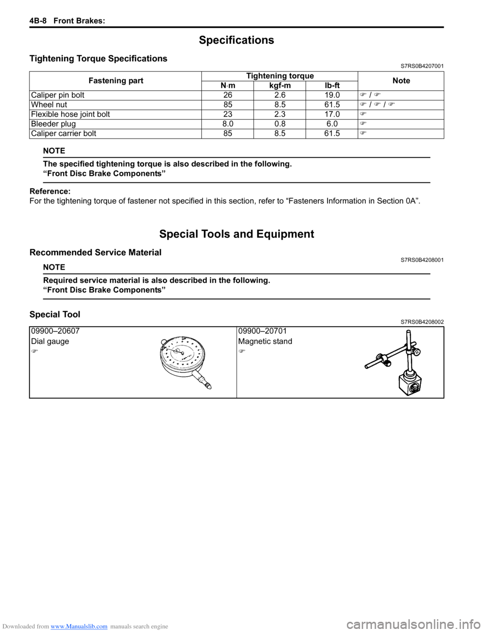
Tightening Torque SpecificationsS7RS0B4207001
NOTE
The specified tightening torque is also described in the following.
“Front Disc Brake Components”
Reference:
For the tightening torque of fastener not specified in this section, refer to “Fasteners Information in Section 0A”.
Special Tools and Equipment
Recommended Service MaterialS7RS0B4208001
NOTE
Required service material is also described in the following.
“Front Disc Brake Components”
Special ToolS7RS0B4208002
Fastening part Tightening torque
Note
N ⋅mkgf-mlb-ft
Caliper pin bolt 26 2.6 19.0 �) / �)
Wheel nut 85 8.5 61.5 �) / �) / �)
Flexible hose joint bolt 23 2.3 17.0 �)
Bleeder plug 8.0 0.8 6.0 �)
Caliper carrier bolt 85 8.5 61.5 �)
09900–2060709900–20701
Dial gauge Magnetic stand
�)�)
Page 525 of 1496
Downloaded from www.Manualslib.com manuals search engine Rear Brakes: 4C-1
Brakes
Rear Brakes
Repair Instructions
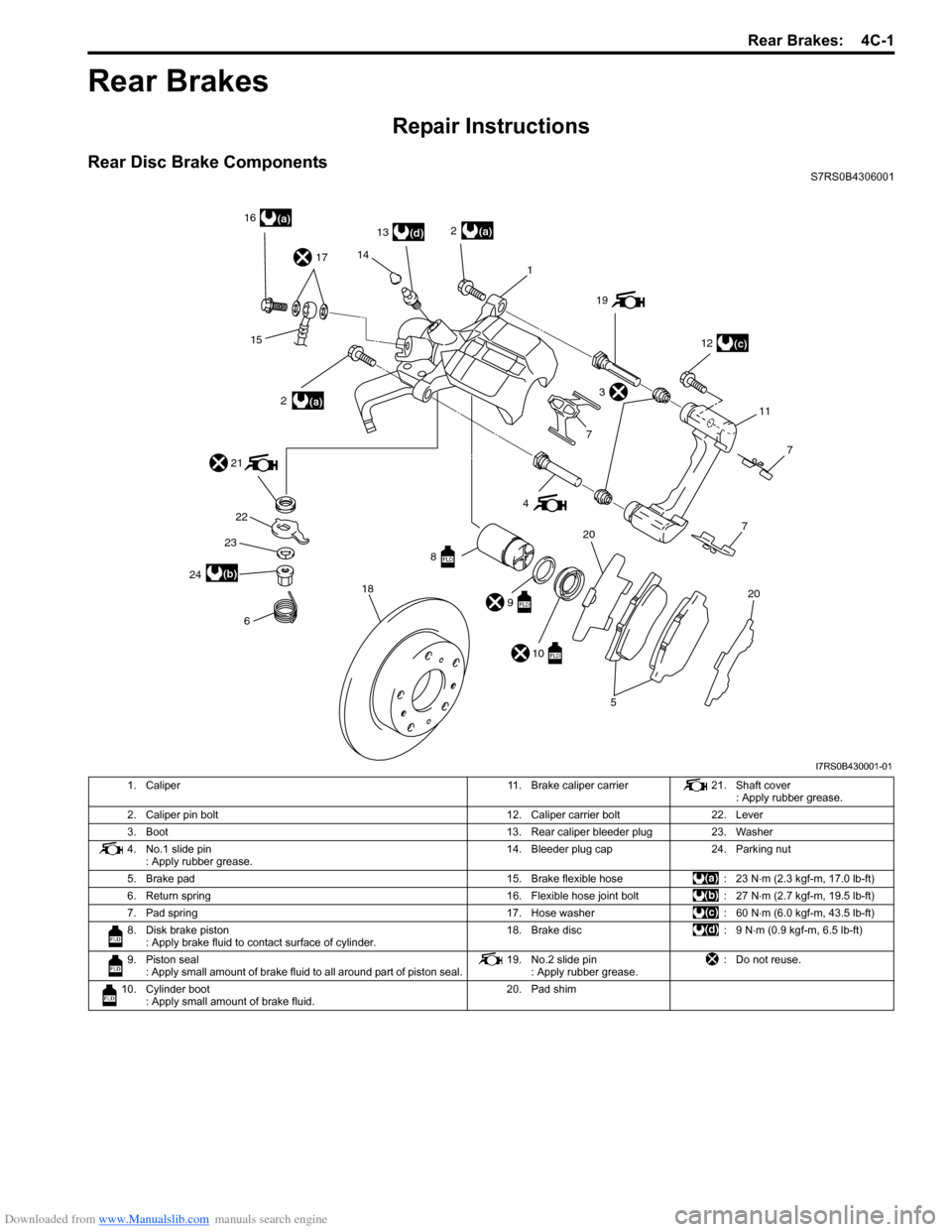
Rear Disc Brake ComponentsS7RS0B4306001
(d)
(c)
(a)
(a)
(a)16171413
2
1
15 2 19
12
117
7
3
7
4
20 20
5
10
9
8
(b)
18
6
24
23
22
21
I7RS0B430001-01
1. Caliper
11. Brake caliper carrier21. Shaft cover
: Apply rubber grease.
2. Caliper pin bolt 12. Caliper carrier bolt22. Lever
3. Boot 13. Rear caliper bleeder plug23. Washer
4. No.1 slide pin : Apply rubber grease. 14. Bleeder plug cap
24. Parking nut
5. Brake pad 15. Brake flexible hose: 23 N⋅m (2.3 kgf-m, 17.0 lb-ft)
6. Return spring 16. Flexible hose joint bolt: 27 N⋅m (2.7 kgf-m, 19.5 lb-ft)
7. Pad spring 17. Hose washer: 60 N⋅m (6.0 kgf-m, 43.5 lb-ft)
8. Disk brake piston : Apply brake fluid to contact surface of cylinder. 18. Brake disc
: 9 N⋅m (0.9 kgf-m, 6.5 lb-ft)
9. Piston seal : Apply small amount of brake fluid to all around part of piston seal. 19. No.2 slide pin
: Apply rubber grease. : Do not reuse.
10. Cylinder boot : Apply small amount of brake fluid. 20. Pad shim
Page 526 of 1496
Downloaded from www.Manualslib.com manuals search engine 4C-2 Rear Brakes:
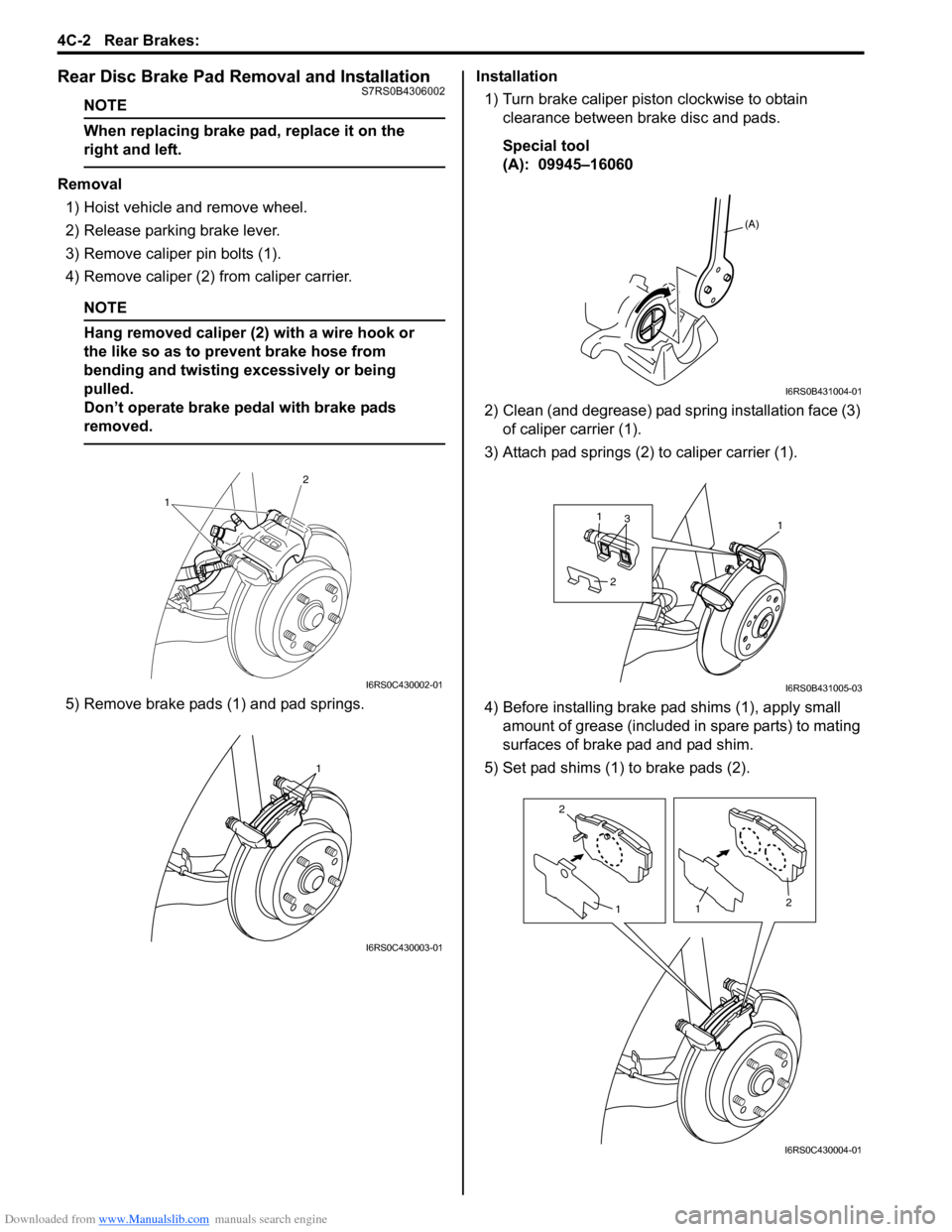
Rear Disc Brake Pad Removal and InstallationS7RS0B4306002
NOTE
When replacing brake pad, replace it on the
right and left.
Removal1) Hoist vehicle and remove wheel.
2) Release parking brake lever.
3) Remove caliper pin bolts (1).
4) Remove caliper (2) from caliper carrier.
NOTE
Hang removed caliper (2) with a wire hook or
the like so as to prevent brake hose from
bending and twisting excessively or being
pulled.
Don’t operate brake pedal with brake pads
removed.
5) Remove brake pads (1) and pad springs. Installation
1) Turn brake caliper piston clockwise to obtain clearance between brake disc and pads.
Special tool
(A): 09945–16060
2) Clean (and degrease) pad spring installation face (3) of caliper carrier (1).
3) Attach pad springs (2) to caliper carrier (1).
4) Before installing brake p ad shims (1), apply small
amount of grease (included in spare parts) to mating
surfaces of brake pad and pad shim.
5) Set pad shims (1) to brake pads (2).
1 2
I6RS0C430002-01
1
I6RS0C430003-01
(A)
I6RS0B431004-01
113
2
I6RS0B431005-03
2
1
1 2
I6RS0C430004-01
Page 527 of 1496
Downloaded from www.Manualslib.com manuals search engine Rear Brakes: 4C-3
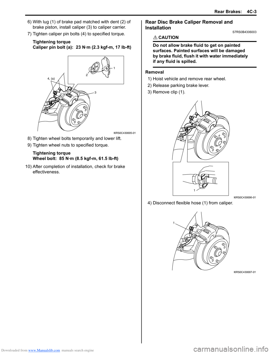
6) With lug (1) of brake pad matched with dent (2) of brake piston, install caliper (3) to caliper carrier.
7) Tighten caliper pin bolts (4) to specified torque.
Tightening torque
Caliper pin bolt (a): 23 N·m (2.3 kgf-m, 17 lb-ft)
8) Tighten wheel bolts temporarily and lower lift.
9) Tighten wheel nuts to specified torque. Tightening torque
Wheel bolt: 85 N·m (8.5 kgf-m, 61.5 lb-ft)
10) After completion of installation, check for brake effectiveness.Rear Disc Brake Caliper Removal and
Installation
S7RS0B4306003
CAUTION!
Do not allow brake fluid to get on painted
surfaces. Painted surfaces will be damaged
by brake fluid, flush it with water immediately
if any fluid is spilled.
Removal
1) Hoist vehicle and remove rear wheel.
2) Release parking brake lever.
3) Remove clip (1).
4) Disconnect flexible hose (1) from caliper.
4, (a) 21
3
I6RS0C430005-01
1
I6RS0C430006-01
1
I6RS0C430007-01