Lower SUZUKI SWIFT 2008 2.G Service Workshop Manual
[x] Cancel search | Manufacturer: SUZUKI, Model Year: 2008, Model line: SWIFT, Model: SUZUKI SWIFT 2008 2.GPages: 1496, PDF Size: 34.44 MB
Page 1095 of 1496
Downloaded from www.Manualslib.com manuals search engine Air Bag System: 8B-57
CAUTION!
• Be sure to perform “Air Bag Diagnostic System Check” before starting diagnosis according to flow.
• When measurement of resistance or voltage is required in this flow, use a tester along with a correct terminal adapter from special tool (Connector test adapter kit).
• When a check for proper connection is required, refer to “Inspection of Intermittent and Poor Connections”.
• If there is open circuit in the air bag wire harnes s, connector or terminal is found damaged, replace
the wire harness, connector and terminal as an assembly.
DTC Will Set when
The resistance of driver or passenger seat belt pretensioner initiator circuit is above a specified value for specified
time.
Flow Test Description
Step 1: Check if malfunction is in seat belt pretensioner.
Step 2: Check seat belt pretensioner initiator circuit.
DTC Troubleshooting
Step Action YesNo
1 1) With ignition switch OFF, re move center pillar lower trim
of driver or passenger side and disconnect seat belt
pretensioner connector “L10” or “L36” (1).
2) Check proper connection to seat belt pretensioner at terminals in “L10” or “L36” connector.
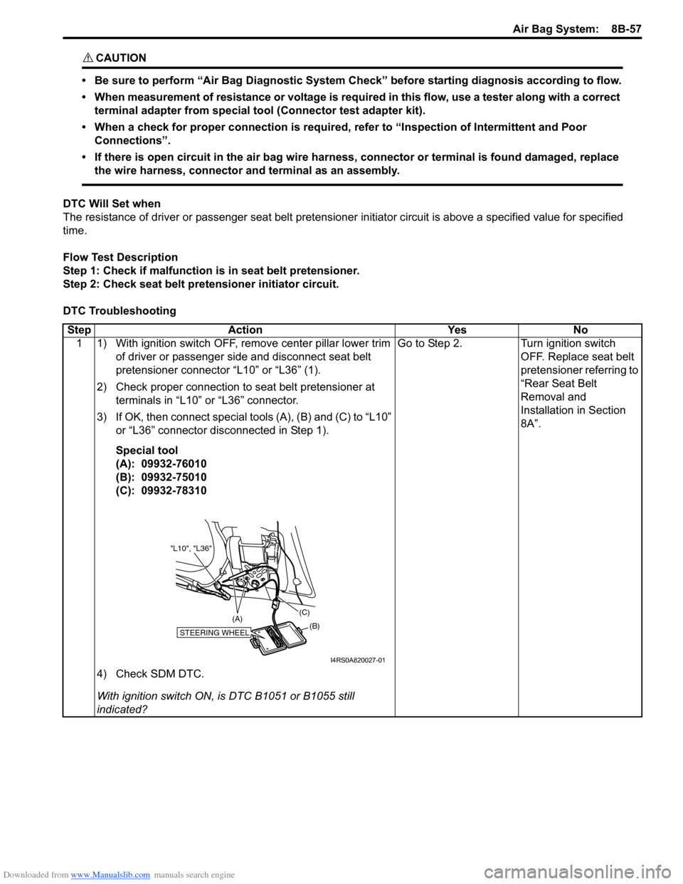
3) If OK, then connect special tools (A), (B) and (C) to “L10” or “L36” connector disconnected in Step 1).
Special tool
(A): 09932-76010
(B): 09932-75010
(C): 09932-78310
4) Check SDM DTC.
With ignition switch ON, is DTC B1051 or B1055 still
indicated? Go to Step 2.
Turn ignition switch
OFF. Replace seat belt
pretensioner referring to
“Rear Seat Belt
Removal and
Installation in Section
8A”.
STEERING WHEEL(B)
(C)
(A)
"L10", "L36"
I4RS0A820027-01
Page 1097 of 1496
Downloaded from www.Manualslib.com manuals search engine Air Bag System: 8B-59
CAUTION!
• Be sure to perform “Air Bag Diagnostic System Check” before starting diagnosis according to flow.
• When measurement of resistance or voltage is required in this flow, use a tester along with a correct terminal adapter from special tool (Connector test adapter kit).
• When a check for proper connection is required, refer to “Inspection of Intermittent and Poor Connections”.
• If there is open circuit in the air bag wire harnes s, connector or terminal is found damaged, replace
the wire harness, connector and terminal as an assembly.
DTC Will Set when
The resistance of driver or passenger seat belt pretensioner initiator circuit is below a specified value for specified
time.
Flow Test Description
Step 1: Check if malfunction is in seat belt pretensioner.
Step 2: Check seat belt pretensioner initiator circuit.
DTC Troubleshooting
Step Action YesNo
1 1) With ignition switch OFF, re move center pillar lower trim
of driver or passenger side and disconnect seat belt
pretensioner connector “L10” or “L36” (1).
2) Check proper connection to seat belt pretensioner at terminals in “L10” or “L36” connector.
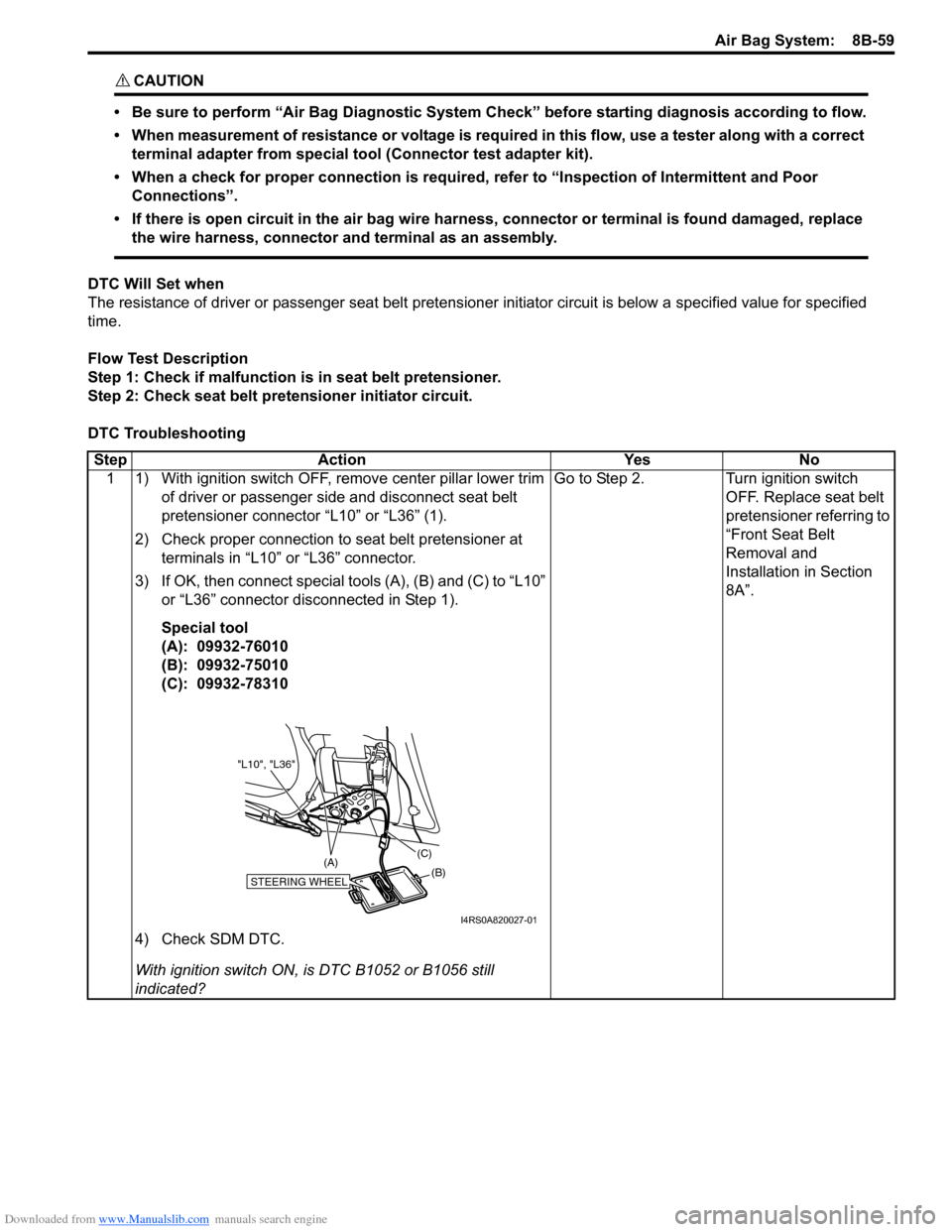
3) If OK, then connect special tools (A), (B) and (C) to “L10” or “L36” connector disconnected in Step 1).
Special tool
(A): 09932-76010
(B): 09932-75010
(C): 09932-78310
4) Check SDM DTC.
With ignition switch ON, is DTC B1052 or B1056 still
indicated? Go to Step 2.
Turn ignition switch
OFF. Replace seat belt
pretensioner referring to
“Front Seat Belt
Removal and
Installation in Section
8A”.
STEERING WHEEL(B)
(C)
(A)
"L10", "L36"
I4RS0A820027-01
Page 1099 of 1496
Downloaded from www.Manualslib.com manuals search engine Air Bag System: 8B-61
CAUTION!
• Be sure to perform “Air Bag Diagnostic System Check” before starting diagnosis according to flow.
• When measurement of resistance or voltage is required in this flow, use a tester along with a correct terminal adapter from special tool (Connector test adapter kit).
• When a check for proper connection is required, refer to “Inspection of Intermittent and Poor Connections”.
• If there is open circuit in the air bag wire harnes s, connector or terminal is found damaged, replace
the wire harness, connector and terminal as an assembly.
DTC Will Set when
The voltage measured at driver or passenger seat belt pr etensioner initiator circuit is below a specified value for
specified time.
Flow Test Description
Step 1: Check if malfunction is in seat belt pretensioner.
Step 2: Check seat belt pretensioner initiator circuit.
DTC Troubleshooting
Step Action YesNo
1 1) With ignition switch OFF, re move center pillar lower trim
of driver or passenger side and disconnect seat belt
pretensioner connector “L10” or “L36” (1).
2) Check proper connection to seat belt pretensioner at terminals in “L10” or “L36” connector.
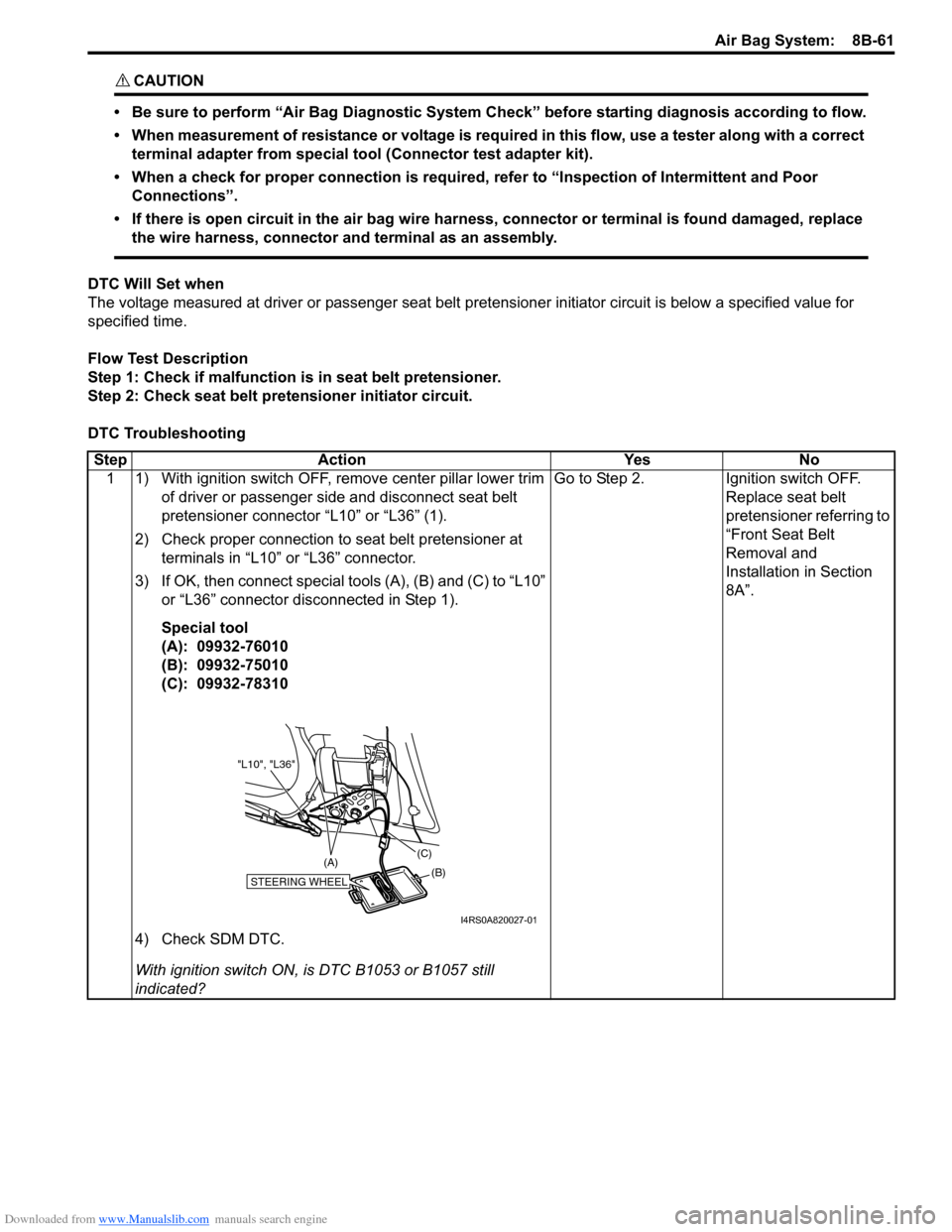
3) If OK, then connect special tools (A), (B) and (C) to “L10” or “L36” connector disconnected in Step 1).
Special tool
(A): 09932-76010
(B): 09932-75010
(C): 09932-78310
4) Check SDM DTC.
With ignition switch ON, is DTC B1053 or B1057 still
indicated? Go to Step 2.
Ignition switch OFF.
Replace seat belt
pretensioner referring to
“Front Seat Belt
Removal and
Installation in Section
8A”.
STEERING WHEEL(B)
(C)
(A)
"L10", "L36"
I4RS0A820027-01
Page 1101 of 1496
Downloaded from www.Manualslib.com manuals search engine Air Bag System: 8B-63
CAUTION!
• Be sure to perform “Air Bag Diagnostic System Check” before starting diagnosis according to flow.
• When measurement of resistance or voltage is required in this flow, use a tester along with a correct terminal adapter from special tool (Connector test adapter kit).
• When a check for proper connection is required, refer to “Inspection of Intermittent and Poor Connections”.
• If there is open circuit in the air bag wire harnes s, connector or terminal is found damaged, replace
the wire harness, connector and terminal as an assembly.
DTC Will Set when
The voltage measured at driver or passenger seat belt pr etensioner initiator circuit is above a specified value for
specified time.
Flow Test Description
Step 1: Check if malfunction is in seat belt pretensioner.
Step 2: Check seat belt pretensioner initiator circuit.
DTC Troubleshooting
Step Action YesNo
1 1) With ignition switch OFF, re move center pillar lower trim
of driver or passenger side and disconnect seat belt
pretensioner connector “L10” and “L36” (1).
2) Check proper connection to seat belt pretensioner at terminals in “L10” or “L36” connector.
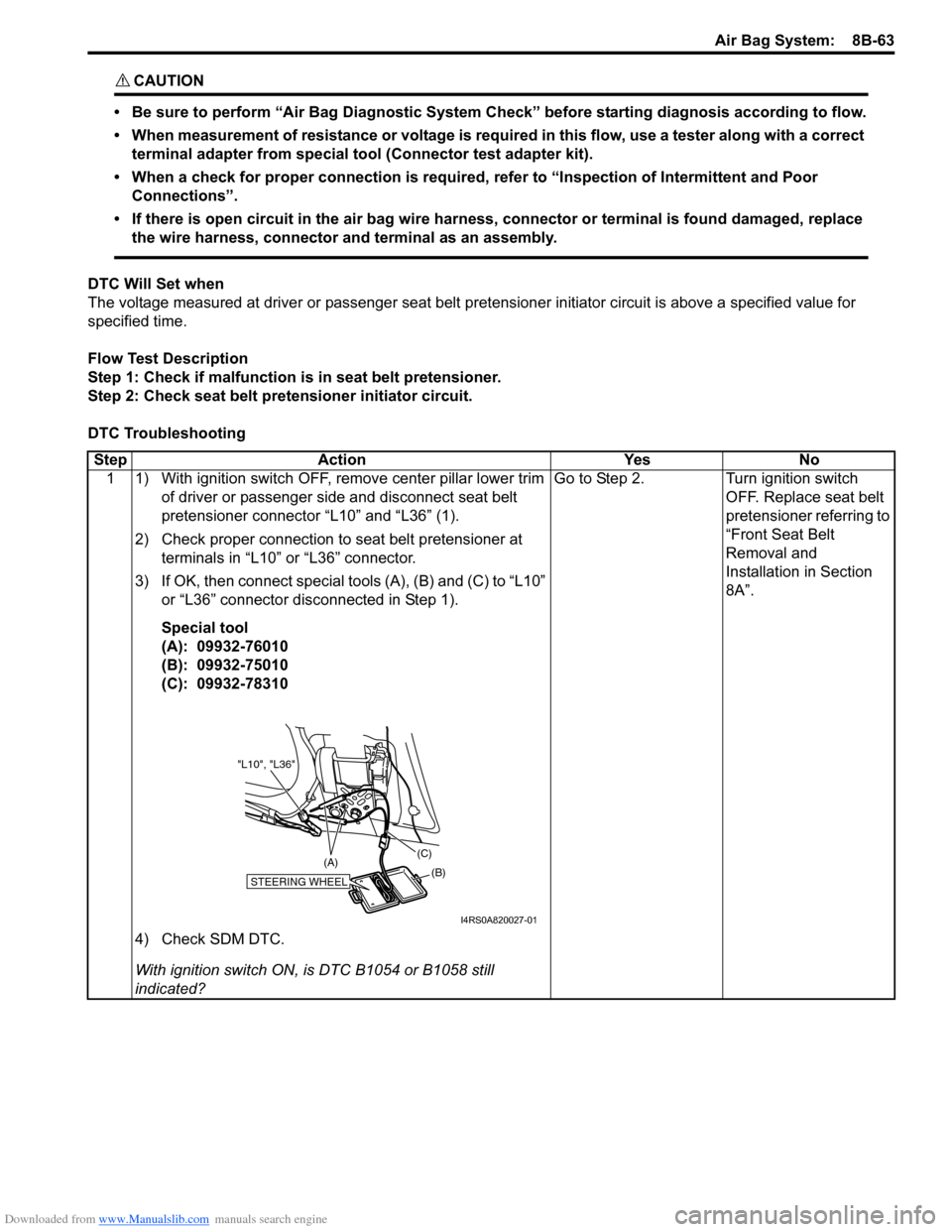
3) If OK, then connect special tools (A), (B) and (C) to “L10” or “L36” connector disconnected in Step 1).
Special tool
(A): 09932-76010
(B): 09932-75010
(C): 09932-78310
4) Check SDM DTC.
With ignition switch ON, is DTC B1054 or B1058 still
indicated? Go to Step 2.
Turn ignition switch
OFF. Replace seat belt
pretensioner referring to
“Front Seat Belt
Removal and
Installation in Section
8A”.
STEERING WHEEL(B)
(C)
(A)
"L10", "L36"
I4RS0A820027-01
Page 1142 of 1496
Downloaded from www.Manualslib.com manuals search engine 8B-104 Air Bag System:
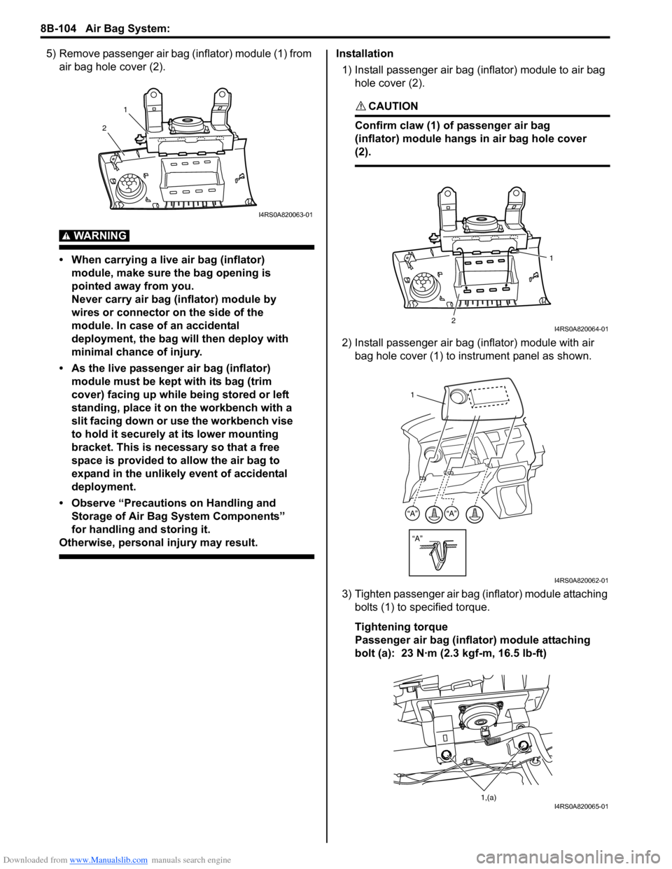
5) Remove passenger air bag (inflator) module (1) from air bag hole cover (2).
WARNING!
• When carrying a live air bag (inflator) module, make sure the bag opening is
pointed away from you.
Never carry air bag (inflator) module by
wires or connector on the side of the
module. In case of an accidental
deployment, the bag will then deploy with
minimal chance of injury.
• As the live passenger air bag (inflator) module must be kept with its bag (trim
cover) facing up while being stored or left
standing, place it on the workbench with a
slit facing down or use the workbench vise
to hold it securely at its lower mounting
bracket. This is necessary so that a free
space is provided to allow the air bag to
expand in the unlikely event of accidental
deployment.
• Observe “Precautions on Handling and Storage of Air Bag System Components”
for handling and storing it.
Otherwise, personal injury may result.
Installation
1) Install passenger air bag (inflator) module to air bag hole cover (2).
CAUTION!
Confirm claw (1) of passenger air bag
(inflator) module hangs in air bag hole cover
(2).
2) Install passenger air bag (inflator) module with air bag hole cover (1) to instrument panel as shown.
3) Tighten passenger air bag (inflator) module attaching bolts (1) to sp ecified torque.
Tightening torque
Passenger air bag (inflator) module attaching
bolt (a): 23 N·m (2.3 kgf-m, 16.5 lb-ft)
1
2
I4RS0A820063-01
2 1I4RS0A820064-01
“A”
“A”“A”
1
I4RS0A820062-01
1,(a)I4RS0A820065-01
Page 1152 of 1496
Downloaded from www.Manualslib.com manuals search engine 8B-114 Air Bag System:
Deployment / Activation Outside of Vehicle
When you intend to return the vehicle to service, deploy
the air bag (inflator) module(s) or activate seat belt
pretensioner(s) outside of the vehicle.1) Turn ignition switch to LOCK position and remove key.
2) Wear safety glasses during this deployment / activation procedure.
3) Check that there is no open, short or damage in special tools (deployment harness (A) and adapter
cable (B)). If any faulty is found, do not use it and be
sure to use new special tool.
Special tool
(A): 09932-75031
(B): 09932–76510
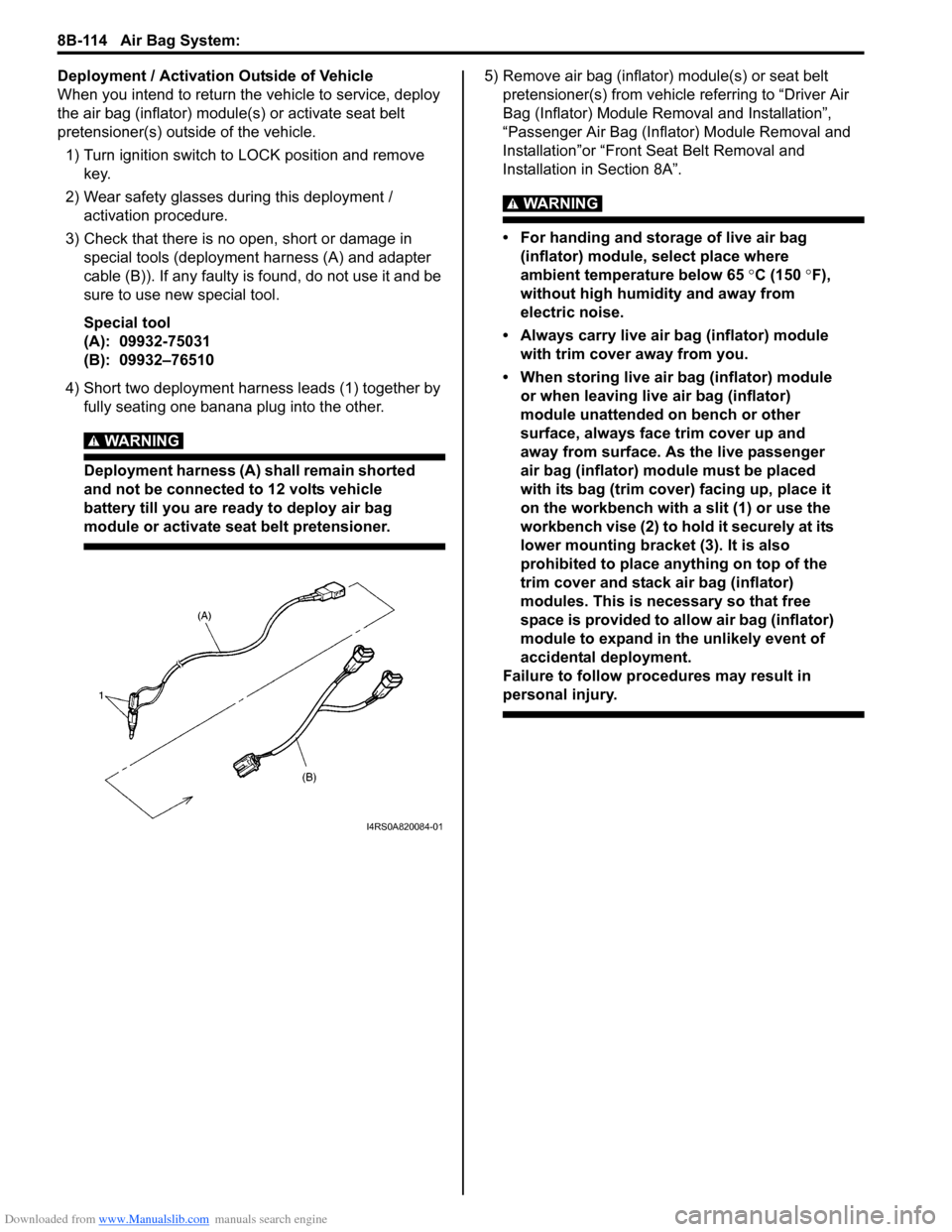
4) Short two deployment harness leads (1) together by fully seating one banana plug into the other.
WARNING!
Deployment harness (A) shall remain shorted
and not be connected to 12 volts vehicle
battery till you are ready to deploy air bag
module or activate seat belt pretensioner.
5) Remove air bag (inflator) module(s) or seat belt pretensioner(s) from vehicle referring to “Driver Air
Bag (Inflator) Module Re moval and Installation”,
“Passenger Air Bag (Inflator) Module Removal and
Installation”or “Front Seat Belt Removal and
Installation in Section 8A”.
WARNING!
• For handing and storage of live air bag (inflator) module, select place where
ambient temperature below 65 °C (150 °F),
without high humidity and away from
electric noise.
• Always carry live air bag (inflator) module with trim cover away from you.
• When storing live air bag (inflator) module or when leaving live air bag (inflator)
module unattended on bench or other
surface, always face trim cover up and
away from surface. As the live passenger
air bag (inflator) module must be placed
with its bag (trim cover) facing up, place it
on the workbench with a slit (1) or use the
workbench vise (2) to hold it securely at its
lower mounting bracket (3). It is also
prohibited to place anything on top of the
trim cover and stack air bag (inflator)
modules. This is necessary so that free
space is provided to allow air bag (inflator)
module to expand in the unlikely event of
accidental deployment.
Failure to follow procedures may result in
personal injury.
I4RS0A820084-01
Page 1153 of 1496
Downloaded from www.Manualslib.com manuals search engine Air Bag System: 8B-115
WARNING!
• For handling and storage of seat belt pretensioner, select place where ambient
temperature is below 65 °C (150 °F),
without high humidity and away from
electric noise.
• Never carry seat belt pretensioner by webbing.
• When placing seat belt pretensioner on workbench or other surface, be sure to lay
it with its exhaust hole (1) side facing up. It
is also prohibited to put something on seat
belt pretensioner.
Otherwise, personal injury may result.
6) Set air bag (inflator) module or seat belt pretensioner
as follows.
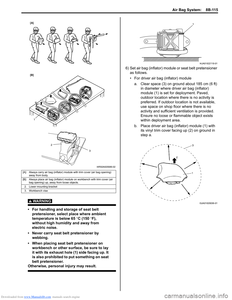
• For driver air bag (inflator) module
a. Clear space (3) on ground about 185 cm (6 ft) in diameter where driver air bag (inflator)
module (1) is set for deployment. Paved,
outdoor location where there is no activity is
preferred. If outdoor location is not available,
use space on shop floor where there is no
activity and sufficient ventilation is provided.
Ensure no loose or flammable object exists
within deployment area.
b. Place driver air bag (inflator) module (1) with its vinyl trim cover facing up (2) on ground in
step a.
[A]: Always carry air bag (inflator) module with trim cover (air bag opening) away from body.
[B]: Always place air bag (inflator) module on workbench with trim cover (air bag opening) up, away from loose objects.
2. Lower mounting bracket
3. Workbench vise
1
2
3
[A]
[B]
I4RS0A820086-02
1
I4JA01822118-01
I3JA01820036-01
Page 1159 of 1496
Downloaded from www.Manualslib.com manuals search engine Air Bag System: 8B-121
Deployment / Activation Inside of Vehicle
When the vehicle will be destroyed, or salvaged for
component parts, deploy the air bag modules and/or
activate seat belt pretensioners installed on vehicle.
NOTE
If equipped with the seat belt pretensioners,
activate both side of seat belt pretensioners
at the same time when using special tool (C).
1) Turn ignition switch to LOCK position, remove key
and put on safety glasses.
2) Remove all loose objects from front seats and instrument panel.
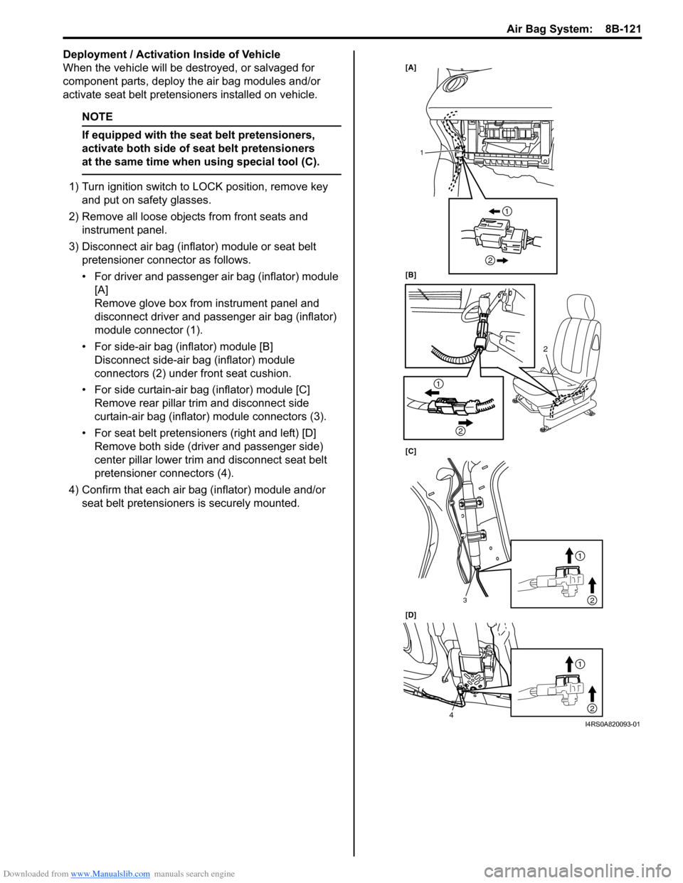
3) Disconnect air bag (inflator) module or seat belt pretensioner connector as follows.
• For driver and passenger air bag (inflator) module [A]
Remove glove box from instrument panel and
disconnect driver and passenger air bag (inflator)
module connector (1).
• For side-air bag (inflator) module [B] Disconnect side-air bag (inflator) module
connectors (2) under front seat cushion.
• For side curtain-air bag (inflator) module [C] Remove rear pillar trim and disconnect side
curtain-air bag (inflator) module connectors (3).
• For seat belt pretensioners (right and left) [D] Remove both side (driver and passenger side)
center pillar lower trim an d disconnect seat belt
pretensioner connectors (4).
4) Confirm that each air bag (inflator) module and/or seat belt pretensioners is securely mounted.
[A]
[B]
[C]
[D]
2
1
3
4
1
2
1
2
1
2
1
2
I4RS0A820093-01
Page 1189 of 1496
Downloaded from www.Manualslib.com manuals search engine Wiring Systems: 9A-18
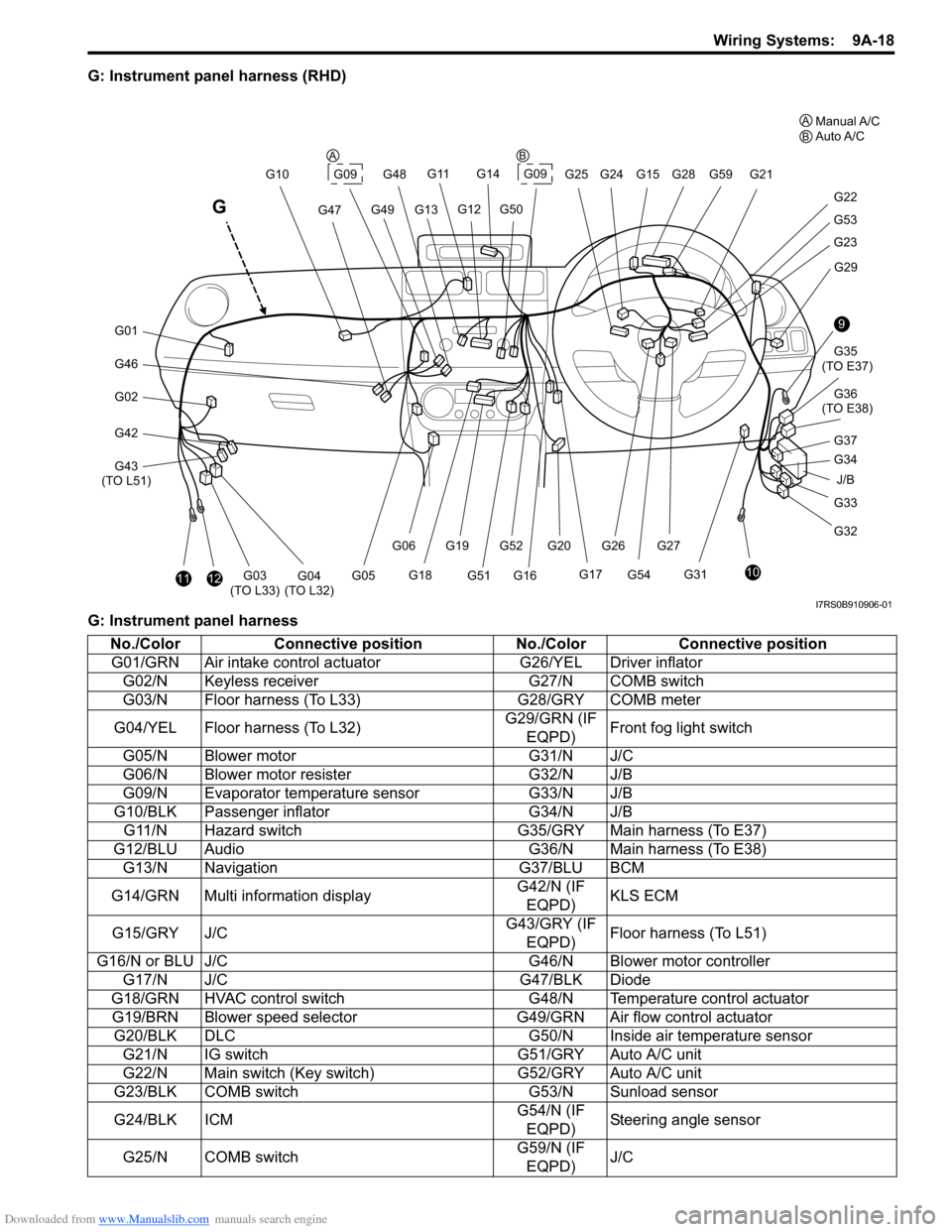
G: Instrument panel harness (RHD)
G: Instrument panel harness
J/B
9
10
G33
G32 G34 G35
(TO E37)
G36
(TO E38)
G31 G29
G23
G53
G22
G21
G28G59
G20G52G27
G54
G261112G03
(TO L33)G04
(TO L32)
G46
G01
G02
G42
G43
(TO L51) G10
G47
G11
G13G49
G14
G09G25 G24G15
G12G50
G48
G17
G16G51
G19
G18
G06
G05
G
G09
G37
A
BManual A/C
Auto A/C
AB
I7RS0B910906-01
No./Color Connective position No./ColorConnective position
G01/GRN Air intake control ac tuatorG26/YEL Driver inflator
G02/N Keyless receiver G27/N COMB switch
G03/N Floor harness (To L33) G28/GRY COMB meter
G04/YEL Floor harness (To L32) G29/GRN (IF
EQPD) Front fog light switch
G05/N Blower motor G31/N J/C
G06/N Blower motor resister G32/N J/B
G09/N Evaporator temperature sensor G33/N J/B
G10/BLK Passenger inflator G34/N J/B
G11/N Hazard switch G35/GRY Main harness (To E37)
G12/BLU Audio G36/N Main harness (To E38)
G13/N Navigation G37/BLU BCM
G14/GRN Multi information display G42/N (IF
EQPD) KLS ECM
G15/GRY J/C G43/GRY (IF
EQPD) Floor harness (To L51)
G16/N or BLU J/C G46/N Blower motor controller
G17/N J/C G47/BLK Diode
G18/GRN HVAC control switch G48/N Temperature control actuator
G19/BRN Blower speed selector G49/GRN Air flow control actuator
G20/BLK DLC G50/N Inside air temperature sensor
G21/N IG switch G51/GRY Auto A/C unit
G22/N Main switch (Key switch) G52/GRY Auto A/C unit
G23/BLK COMB switch G53/N Sunload sensor
G24/BLK ICM G54/N (IF
EQPD) Steering angle sensor
G25/N COMB switch G59/N (IF
EQPD) J/C
Page 1190 of 1496
Downloaded from www.Manualslib.com manuals search engine 9A-19 Wiring Systems:
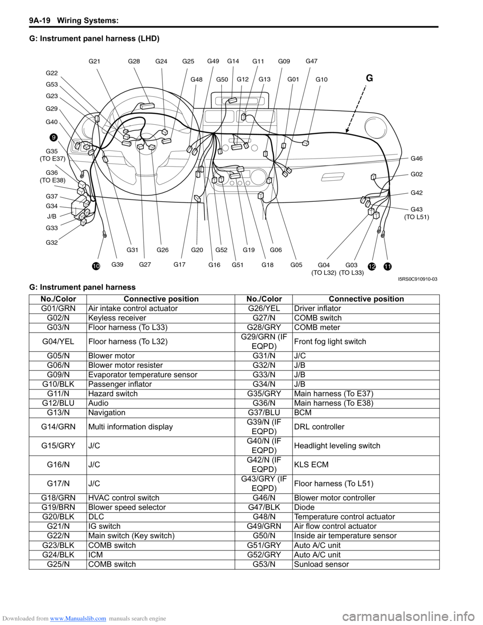
G: Instrument panel harness (LHD)
G: Instrument panel harness
J/B
9
10
G33
G32 G34 G35
(TO E37)
G36
(TO E38)
G29
G40
G23
G53
G22 G21
G28
G20G52
G27G39 G26
G31
1112G03
(TO L33)G04
(TO L32)
G46
G02
G42
G43
(TO L51)
G10
G47G11
G13G01
G14
G49
G50G48
G25
G24
G12
G17
G16G51G19
G18
G06
G05
G
G09
G37
I5RS0C910910-03
No./Color Connective position No./ColorConnective position
G01/GRN Air intake control ac tuatorG26/YEL Driver inflator
G02/N Keyless receiver G27/N COMB switch
G03/N Floor harness (To L33) G28/GRY COMB meter
G04/YEL Floor harness (To L32) G29/GRN (IF
EQPD) Front fog light switch
G05/N Blower motor G31/N J/C
G06/N Blower motor resister G32/N J/B
G09/N Evaporator temperature sensor G33/N J/B
G10/BLK Passenger inflator G34/N J/B
G11/N Hazard switch G35/GRY Main harness (To E37)
G12/BLU Audio G36/N Main harness (To E38)
G13/N Navigation G37/BLU BCM
G14/GRN Multi information display G39/N (IF
EQPD) DRL controller
G15/GRY J/C G40/N (IF
EQPD) Headlight leveling switch
G16/N J/C G42/N (IF
EQPD) KLS ECM
G17/N J/C G43/GRY (IF
EQPD) Floor harness (To L51)
G18/GRN HVAC control switch G46/N Blower motor controller
G19/BRN Blower speed selector G47/BLK Diode
G20/BLK DLC G48/N Temperature control actuator
G21/N IG switch G49/GRN Air flow control actuator
G22/N Main switch (Key switch) G50/N Inside air temperature sensor
G23/BLK COMB switch G51/GRY Auto A/C unit
G24/BLK ICM G52/GRY Auto A/C unit
G25/N COMB switch G53/N Sunload sensor