Lower SUZUKI SWIFT 2008 2.G Service Workshop Manual
[x] Cancel search | Manufacturer: SUZUKI, Model Year: 2008, Model line: SWIFT, Model: SUZUKI SWIFT 2008 2.GPages: 1496, PDF Size: 34.44 MB
Page 1205 of 1496
Downloaded from www.Manualslib.com manuals search engine Wiring Systems: 9A-34
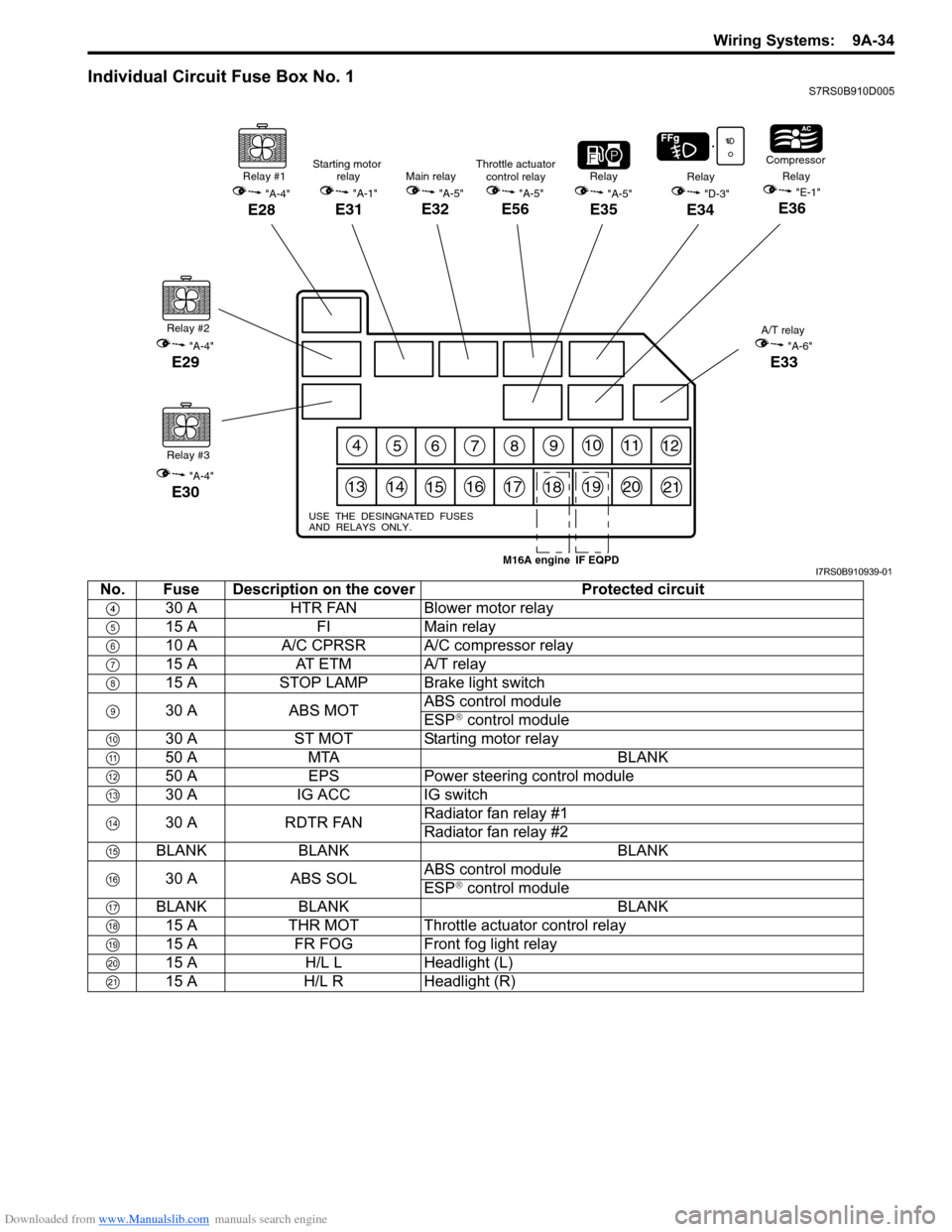
Individual Circuit Fuse Box No. 1S7RS0B910D005
456789101112
131415161718192021
USE THE DESINGNATED FUSES
AND RELAYS ONLY.
Relay #1
"A-4"
E28
Relay #2
"A-4"
E29
Relay #3
"A-4"
E30
"A-5"
E35
RelayRelay
"D-3"
E34
Compressor
Relay"E-1"
E36
A/T relay
"A-6"
E33
Main relay
"A-5"
E32
Starting motor relay
"A-1"
E31
Throttle actuatorcontrol relay
"A-5"
E56
IF EQPDM16A engineI7RS0B910939-01
No. Fuse Description on the cover Protected circuit
30 A HTR FAN Blower motor relay
15 A FIMain relay
10 A A/C CPRSR A/C compressor relay
15 A AT ETM A/T relay
15 A STOP LAMP Brake light switch
30 A ABS MOT ABS control module
ESP
® control module
30 A ST MOT Starting motor relay
50 A MTA BLANK
50 A EPS Power steering control module
30 A IG ACC IG switch
30 A RDTR FAN Radiator fan relay #1
Radiator fan relay #2
BLANK BLANK BLANK
30 A ABS SOL ABS control module
ESP
® control module
BLANK BLANK BLANK 15 A THR MOT Throttle actuator control relay
15 A FR FOG Front fog light relay
15 A H/L L Headlight (L)
15 A H/L R Headlight (R)
Page 1207 of 1496
Downloaded from www.Manualslib.com manuals search engine Wiring Systems: 9A-36
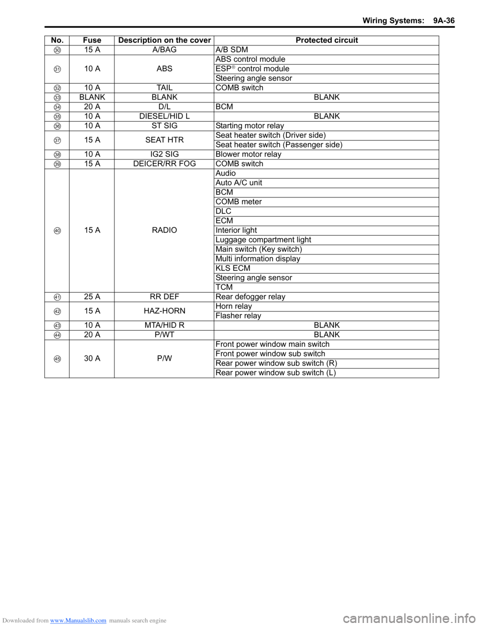
15 AA/BAG A/B SDM
10 A ABSABS control module
ESP
® control module
Steering angle sensor
10 A TAIL COMB switch
BLANK BLANK BLANK 20 A D/L BCM
10 A DIESEL/HID L BLANK
10 A ST SIG Starting motor relay
15 A SEAT HTR Seat heater switch (Driver side)
Seat heater switch (Passenger side)
10 A IG2 SIG Blower motor relay
15 A DEICER/RR FOG COMB switch
15 A RADIO Audio
Auto A/C unit
BCM
COMB meter
DLC
ECM
Interior light
Luggage compartment light
Main switch (Key switch)
Multi information display
KLS ECM
Steering angle sensor
TCM
25 A RR DEF Rear defogger relay
15 A HAZ-HORN Horn relay
Flasher relay
10 A MTA/HID R BLANK
20 A P/WT BLANK
30 A P/W Front power window main switch
Front power window sub switch
Rear power window sub switch (R)
Rear power window sub switch (L)
No. Fuse Description on the cover Protected circuit
Page 1210 of 1496
Downloaded from www.Manualslib.com manuals search engine 9A-39 Wiring Systems:
1IG2FL2
6
Lamp FL (FL BOX)
1A/B CONT4A/B SIG
3K-LINE2A/B SIGNAL
9A/B SIGNAL8K-LINE
2311BCM ;IG1
22D/UL-IN21D/L-IN D/SL-IN
18SECURITY IN6Serial OUT
14TAIL BCM WNG, etc12ANSWER BACK
17RR DEF CONTROL1D/L (+B)
2BCM15DEICER CONTROL
10ACC (BCM)7DOME LP CONT
20GND (POWER)16R-WIP (CONT)
3SIGNAL GND (BCM)
7IG
1LP-L5LP-R
8+B6SW-L
3GND4SW-R
2HAZ
DOME LP POWER5DOME LP DOOR4*3GND (Roof)6HTR4Starter SW1IG 25ACC SW3IG2SW2IG 1
18107G33415G347G3419G341G3412G339G3311G343G342G348G34166G336G345G33810511G3313G344G341G3320G342G339G343G3312G3414G34
10E395E4112E419E4114E411E418E412E4111E413E416E395E3916E417E414E392E399E393E397E3910E41
DEF LP
RR FOG SW DEICER LP
*TAIL SW (Upper)
TAIL SW (HAZ,ASH,ILL) TURN-L
TURN-R
METER (L)
METER (R)
HAZARD SW HORN SW
Serial INF DISP
A/C PANEL
*MTR Power,etc
IMMOBI IG
A/C PANEL
*
*
RADIO, CLOCK
A/B SIGCIGAR
*F-WIP*
*GND (IP)
SIGNAL GND (IP)
*
*
*
IG Coil, etc EPS AT
ABS CONT
BACK (SHIFT) STOP SW
ABS CONT EPI
BUL IN
HORN
FR TURN (R)
FR TURN (L) POSI LP
EPI
DEICER
*F-Washer
F.WIP
HTR Fuse (30A)
ST RLY COIL
4L0515L0516L055L059L05212L0513L0614L067L0615L0614L0511L056L065L068L057L056L0518L053L051L0510L059L0610L061L063L062L068L0611L064L06
SIGNAL GND (FL)
SEAT HEATER
P/W
R-WIP (+) R-WIP (-)*
ACC SOCKET
R/C MIR (ACC)
*
*
*
LUGGAGE LAMPMTA SHIFT LEVER SW
*
*
RR DEF
HTR MIR (L)
HTR MIR (R)
P/W DR
TAIL LP, LICENSE
R-TURN (L)
RR-TURN (R)
D/ULD/L
D-SL
BUL-L
STOP LP
MTA
*
*
IG COIL 15AMETER 10A A/BAG 15A
IG1 SIG 10A ABS 10A
BACK 10A
TAIL 10AD/L 20A
P/WT 20A
RR DEF 20A
DEICER/RR FOG 15A
MTA/HID R 10A
ACC 1 15A
ACC 2 15A
WIPER 15A P/W 30A
*Spare-1
SEAT HTR 15A IG2 SIG 10AST SIG 10A
HAZ-HORN 15A
DIESEL/HID L 10A *Spare-2 RR DEF RLY
DEICER RLY HORN RLY
P-WIP RLY
BLOWER MOTOR RLY
G34 G34
G33
G34
G33
G34 G33
L05
RADIO 15A
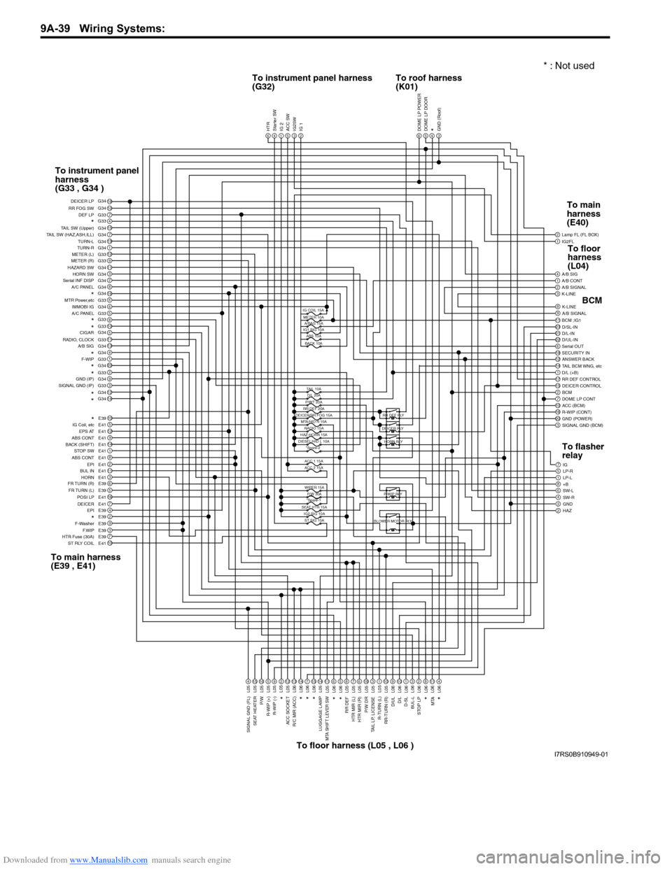
To instrument panel harness
(G32) To roof harness
(K01)
To instrument panel
harness
(G33 , G34 )
To main harness
(E39 , E41) To floor harness (L05 , L06 ) To main
harness
(E40)
BCM
To flasher
relay To floor
harness
(L04)
* : Not used
I7RS0B910949-01
Page 1215 of 1496
Downloaded from www.Manualslib.com manuals search engine Wiring Systems: 9A-44
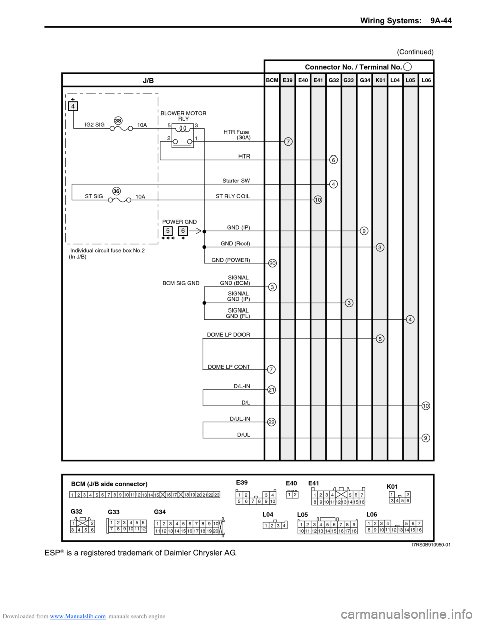
ESP® is a registered trademark of Daimler Chrysler AG.
BCM (J/B side connector)
34
1
2 5
15
14
12
13
10
11
9
8
6
7
17
161821 22
19
20
23
1234578 11 6
12
91034 6 52
1
G33
G32
G34
10
11 12 13 14 15 16 17 18 19 123456789
20
345612K01
23414
3
561214
11
10 157
2113 16
98
6
5
4
3
2
1
7
11
10
9
8
15
14
13
12 16
L04
L06
E41
21
12 34 5 6 78 9
15 16 17 18
1110 12 13 14
1
234
5 678 910
E39
L05
E40
E39 E41E40
BCM G34G33G32 K01 L04 L05 L06J/B
9
3
3
20
3
4
(Continued)
GND (IP)
POWER GND
BCM SIG GND GND (Roof)
GND (POWER)
SIGNAL
GND (FL) SIGNAL
GND (IP) SIGNAL
GND (BCM)
4
4
10
Starter SW
ST RLY COIL
ST SIG 10A36
Individual circuit fuse box No.2
(In J/B)
7
6
BLOWER MOTOR RLY
HTR
HTR Fuse
(30A)
IG2 SIG 10A38
5
7
DOME LP DOOR
DOME LP CONT
21
22
10
9
D/L-IN D/L
D/UL-IND/UL
3
5
2 1
Connector No. / Terminal No.
56
I7RS0B910950-01
Page 1223 of 1496
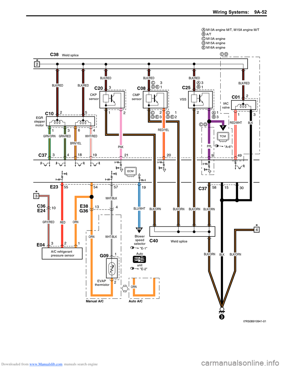
Downloaded from www.Manualslib.com manuals search engine Wiring Systems: 9A-52
"E-1"
"E-2"
EGR
stepper motor
PPL
P
"A-6"
AB
AB
CD
CD
ECM
2
3
REDORNGRY/RED
EVAP
thermistor
1
2G09
13
ORN
ORN
E38
G36
BW
Blower
speed
selector
Auto
unit
A/C refrigerant
pressure sensor
E04
C10
BRN/YEL
WHT/REDGRN/RED
6
4312
5
CKP
sensor CMP
sensor VSS
TCM
C37
BLK
3
155830
C25
21
3CDE12CDE23 3
1
CDE31
1 2
3
C08
C20
C37
18 19
4320
219
PNK
RED/YEL
E2354
55
C36
E2410
1
2
3
19
4
RED/WHT
49
BLK/RED
BLK
C012
1 3
IAC
valve
BLU/WHT
GRN/ORN
WHT/BLK
57
4
WHT/BLK
BLK/RED
BLK/ORNBLK/ORNBLK/ORNBLK/ORN
C40Weld splice
BLK/ORNBLK/ORN
C38Weld splice
BLK/REDBLK/RED
BLK/REDBLK/RED
M13A engine M/T, M15A engine M/T
A/T
M13A engine
M15A engine
M16A engine
ABCDE
Manual A/C
Auto A/C
I7RS0B910941-01
Page 1232 of 1496
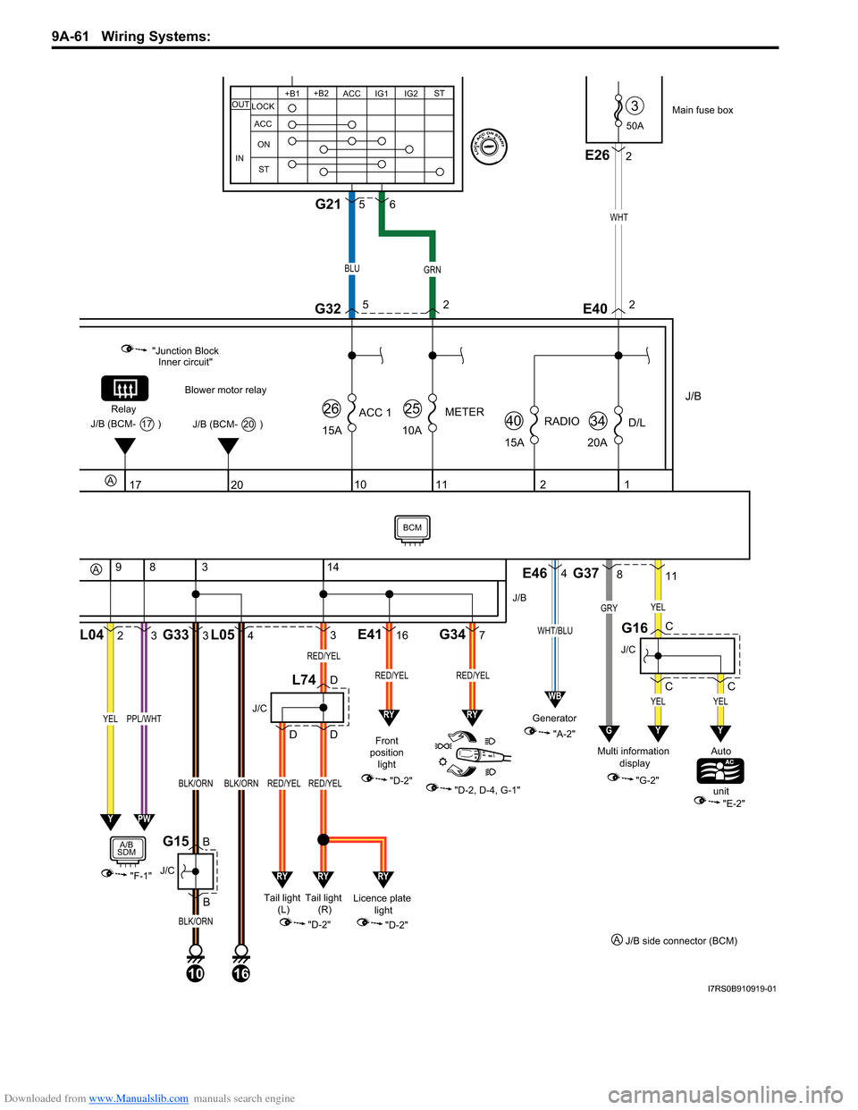
Downloaded from www.Manualslib.com manuals search engine 9A-61 Wiring Systems:
50A
3
J/B
15ARADIO
40
2
15A
ACC 1
26
10
1
20AD/L
34
11
10A
METER
25
Main fuse box
WHT
E402
20
Blower motor relay
"Junction Block Inner circuit"
Relay
J/B (BCM- 20 )J/B (BCM- 17 )
17
2L04
9
3
83
B BG33
3
4L05
10
J/C
G15
BLK/ORN
BLK/ORN
16
BLK/ORN
"F-1"
YELPPL/WHT
A/B
SDM
14
316E417G34
Front
position light
"D-2"
"D-2, D-4, G-1"
J/B
RED/YELRED/YEL
J/C
L74D
DD
Licence plate light
"D-2"
YPW
"A-2"
Generator
E464
WHT/BLU
WB
RYRY
RYRYRY
Tail light
(R)
Tail light
(L)
"D-2"
RED/YEL
RED/YEL
RED/YEL
811
C CG37
J/C
G16
YEL
GRYYEL
GY
C
YEL
Y
"G-2"
Multi information
display Auto
unit
"E-2"
A
A
J/C
2E26
+B1
LOCK
ACC
ON
ST ACC IG1 IG2
STOUT
IN
+B2
BLUGRN
G3252
56G21
J/B side connector (BCM)
A
BCM
I7RS0B910919-01
Page 1261 of 1496
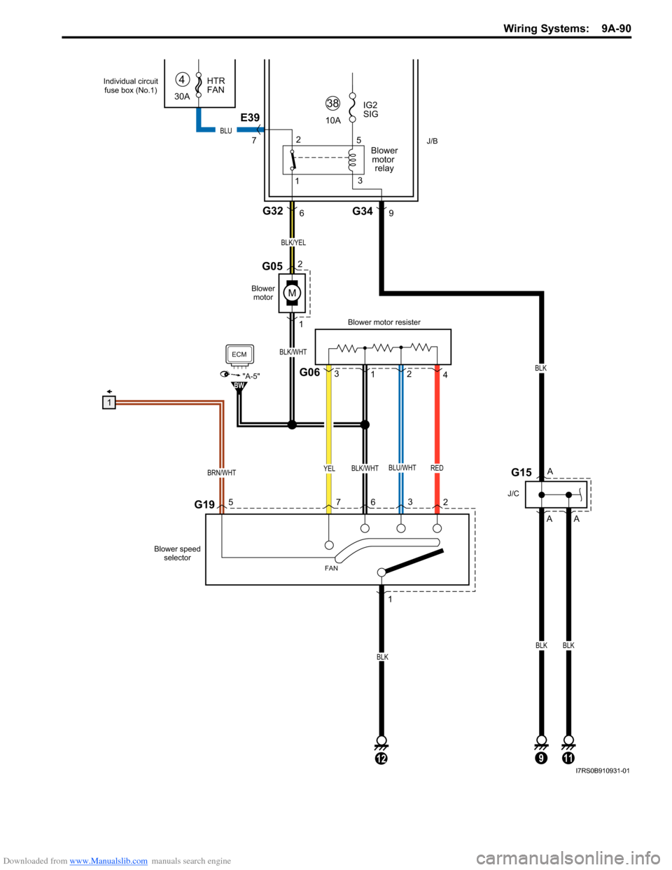
Downloaded from www.Manualslib.com manuals search engine Wiring Systems: 9A-90
RED
M
YELBLU/WHTBLK/WHT
G195
BRN/WHT
J/B
BLK/WHT
BLK/YEL
1
2G05
12
BLK
G06
Blower motor resister
1
3
4
2
Blower
motor
G326
1
72
3
6
FAN
ECM
"A-5"BW
Blower speed
selector
12
5
3
30A HTR
FAN
4
10A
38IG2
SIG
Blowermotor relay
E39
7
G349
G15
J/C
9
A
A
A
BLK
BLK
11
BLK
BLU
1
Individual circuit fuse box (No.1)
I7RS0B910931-01
Page 1263 of 1496
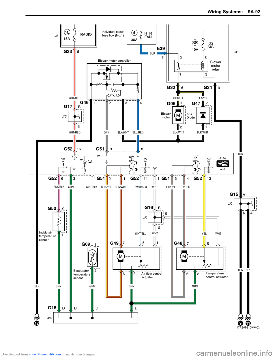
Downloaded from www.Manualslib.com manuals search engine Wiring Systems: 9A-92
G091
2
346
1698G52 G51
G52 G52
G51 G51G52
1
3
7
G495
6
M
G48
M
2
31141413
341
M
2G46
5G33
WHT/RED
WHT/RED
BLK/WHT
GRY/REDGRY/BLUWHTWHT/BLUBRN/WHTBRN/YELWHT/BLKGRN
WHTYELWHTWHT/BLU
GRNGRNBLKGRNGRN
BLK/YELBLK/YEL
BLK/WHTGRYBLK/WHTBLU/RED
Blower motor controller
A/C
DiodeAutounit
Blower
motor
15A RADIO
Evaporator
temperature
sensor Air flow control
actuator
Temperature
control actuator
40
635
71 2
G47
G051
2 1
5V5V
5V5V 12V
12V
12V
J/B
J/B
G326
1 2
5
3
30A HTR
FAN
4
10A
38IG2
SIG
Blowermotorrelay
E39
7
G349
G15
J/C
912
A
A
BLK
11
A
BLKBLK
BLU
J/C
B BG16
B
G16
J/C
DDDD
G17
J/C
B
B
Individual circuit fuse box (No.1)
G502
1
PNK/BLK
Inside air
temperature
sensor
5V
I7RS0B910946-02
Page 1302 of 1496
Downloaded from www.Manualslib.com manuals search engine 9C-7 Instrumentation / Driver Info. / Horn:
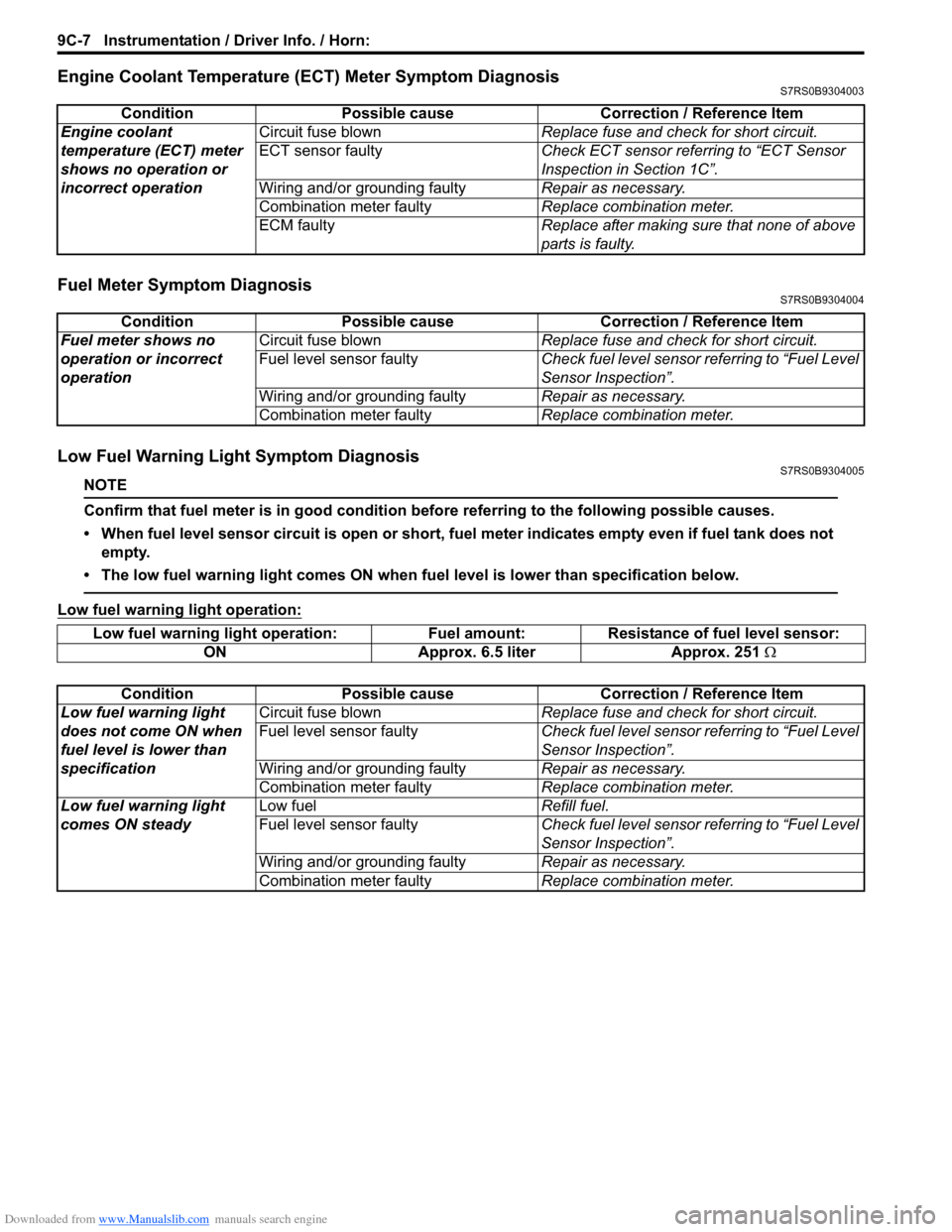
Engine Coolant Temperature (ECT) Meter Symptom DiagnosisS7RS0B9304003
Fuel Meter Symptom DiagnosisS7RS0B9304004
Low Fuel Warning Light Symptom DiagnosisS7RS0B9304005
NOTE
Confirm that fuel meter is in good condition before referring to the following possible causes.
• When fuel level sensor circuit is open or short, fuel meter indicates empty even if fuel tank does not empty.
• The low fuel warning light comes ON when fu el level is lower than specification below.
Low fuel warning light operation:
ConditionPossible cause Correction / Reference Item
Engine coolant
temperature (ECT) meter
shows no operation or
incorrect operation Circuit fuse blown
Replace fuse and check for short circuit.
ECT sensor faulty Check ECT sensor referring to “ECT Sensor
Inspection in Section 1C”.
Wiring and/or grounding faulty Repair as necessary.
Combination meter faulty Replace combination meter.
ECM faulty Replace after making sure that none of above
parts is faulty.
ConditionPossible cause Correction / Reference Item
Fuel meter shows no
operation or incorrect
operation Circuit fuse blown
Replace fuse and check for short circuit.
Fuel level sensor faulty Check fuel level sensor referring to “Fuel Level
Sensor Inspection”.
Wiring and/or grounding faulty Repair as necessary.
Combination meter faulty Replace combination meter.
Low fuel warning light operation: Fuel amount: Resistance of fuel level sensor:
ON Approx. 6.5 liter Approx. 251 Ω
Condition Possible cause Correction / Reference Item
Low fuel warning light
does not come ON when
fuel level is lower than
specification Circuit fuse blown
Replace fuse and check for short circuit.
Fuel level sensor faulty Check fuel level sensor referring to “Fuel Level
Sensor Inspection”.
Wiring and/or grounding faulty Repair as necessary.
Combination meter faulty Replace combination meter.
Low fuel warning light
comes ON steady Low fuel
Refill fuel.
Fuel level sensor faulty Check fuel level sensor referring to “Fuel Level
Sensor Inspection”.
Wiring and/or grounding faulty Repair as necessary.
Combination meter faulty Replace combination meter.
Page 1306 of 1496
Downloaded from www.Manualslib.com manuals search engine 9C-11 Instrumentation / Driver Info. / Horn:
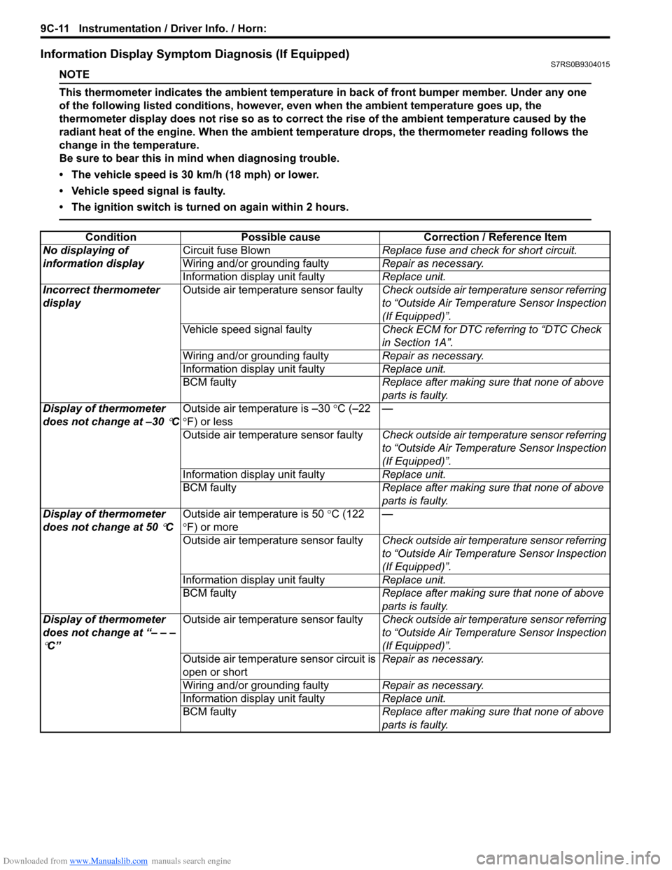
Information Display Symptom Diagnosis (If Equipped)S7RS0B9304015
NOTE
This thermometer indicates the ambient temperature in back of front bumper member. Under any one
of the following listed conditions, however, even when the ambient temperature goes up, the
thermometer display does not rise so as to correct the rise of the ambient temperature caused by the
radiant heat of the engine. When the ambient temperature drops, the thermometer reading follows the
change in the temperature.
Be sure to bear this in mind when diagnosing trouble.
• The vehicle speed is 30 km/h (18 mph) or lower.
• Vehicle speed signal is faulty.
• The ignition switch is turned on again within 2 hours.
ConditionPossible cause Correction / Reference Item
No displaying of
information display Circuit fuse Blown
Replace fuse and check for short circuit.
Wiring and/or grounding faulty Repair as necessary.
Information display unit faulty Replace unit.
Incorrect thermometer
display Outside air temperature sensor faulty
Check outside air temperature sensor referring
to “Outside Air Temperature Sensor Inspection
(If Equipped)”.
Vehicle speed signal faulty Check ECM for DTC referring to “DTC Check
in Section 1A”.
Wiring and/or grounding faulty Repair as necessary.
Information display unit faulty Replace unit.
BCM faulty Replace after making sure that none of above
parts is faulty.
Display of thermometer
does not change at –30
°C Outside air temperature is –30
°C (–22
° F) or less —
Outside air temperature sensor faulty Check outside air temperature sensor referring
to “Outside Air Temperature Sensor Inspection
(If Equipped)”.
Information display unit faulty Replace unit.
BCM faulty Replace after making sure that none of above
parts is faulty.
Display of thermometer
does not change at 50
°C Outside air temperature is 50
°C (122
° F) or more —
Outside air temperature sensor faulty Check outside air temperature sensor referring
to “Outside Air Temperature Sensor Inspection
(If Equipped)”.
Information display unit faulty Replace unit.
BCM faulty Replace after making sure that none of above
parts is faulty.
Display of thermometer
does not change at “– – –
°C” Outside air temperature sensor faulty
Check outside air temperature sensor referring
to “Outside Air Temperature Sensor Inspection
(If Equipped)”.
Outside air temperature sensor circuit is
open or short Repair as necessary.
Wiring and/or grounding faulty Repair as necessary.
Information display unit faulty Replace unit.
BCM faulty Replace after making sure that none of above
parts is faulty.