WIRE SUZUKI SWIFT 2008 2.G Service Workshop Manual
[x] Cancel search | Manufacturer: SUZUKI, Model Year: 2008, Model line: SWIFT, Model: SUZUKI SWIFT 2008 2.GPages: 1496, PDF Size: 34.44 MB
Page 475 of 1496
Downloaded from www.Manualslib.com manuals search engine Wheels and Tires: 2D-8
Tire Mounting and DismountingS7RS0B2406004
CAUTION!
When installing tire which has arrow
indicating tire rotation direction to wheel,
make sure that this tire rotation direction is
same as actual tire rotation direction when
vehicle is moving forward. Otherwise, it is
not possible to install wheel with tire to
vehicle in specified direction.
Use a tire changing machine to mount or dismount tires.
Follow equipment manufacturer’s instructions. Do not
use hand tools or tire irons al one to change tires as they
may damage tire beads or wheel rim.
Rim bead seats should be cleaned with a wire brush or
coarse steel wool to remove lubricants, old rubber and
light rust. Before mounting or dismounting a tire, bead
area should be well lubricated with approved tire
lubricant.
After mounting, inflate to specified pressure shown on
tire placard so that beads are completely seated.
WARNING!
Do not stand over tire when inflating. Bead
may break when bead snaps over rim’s safety
hump and cause serious personal injury.
Do not exceed 330 kpa (47.9 psi) pressure
when inflating. If 330 kpa (47.9 psi) pressure
will not seat beads, deflate, re-lubricate and
reinflate.
Over inflation may cause bead to break and
cause serious personal injury.
Install valve core and inflate to proper pressure.
Tire RepairS7RS0B2406005
There are many different materials and techniques on
the market to repair tires. As not all of these work on all
types of tires, tire manufacturers have published detailed
instructions on how and when to repair tires. These
instructions can be obtained from each tire
manufacturer.
Tire Repair for Emergency Repaired-Tire with
Sealant
S7RS0B2406006
WARNING!
Be sure to observe “Precaution for
Emergency Flat Tire Repair Kit”. Otherwise,
your health may be ruined.
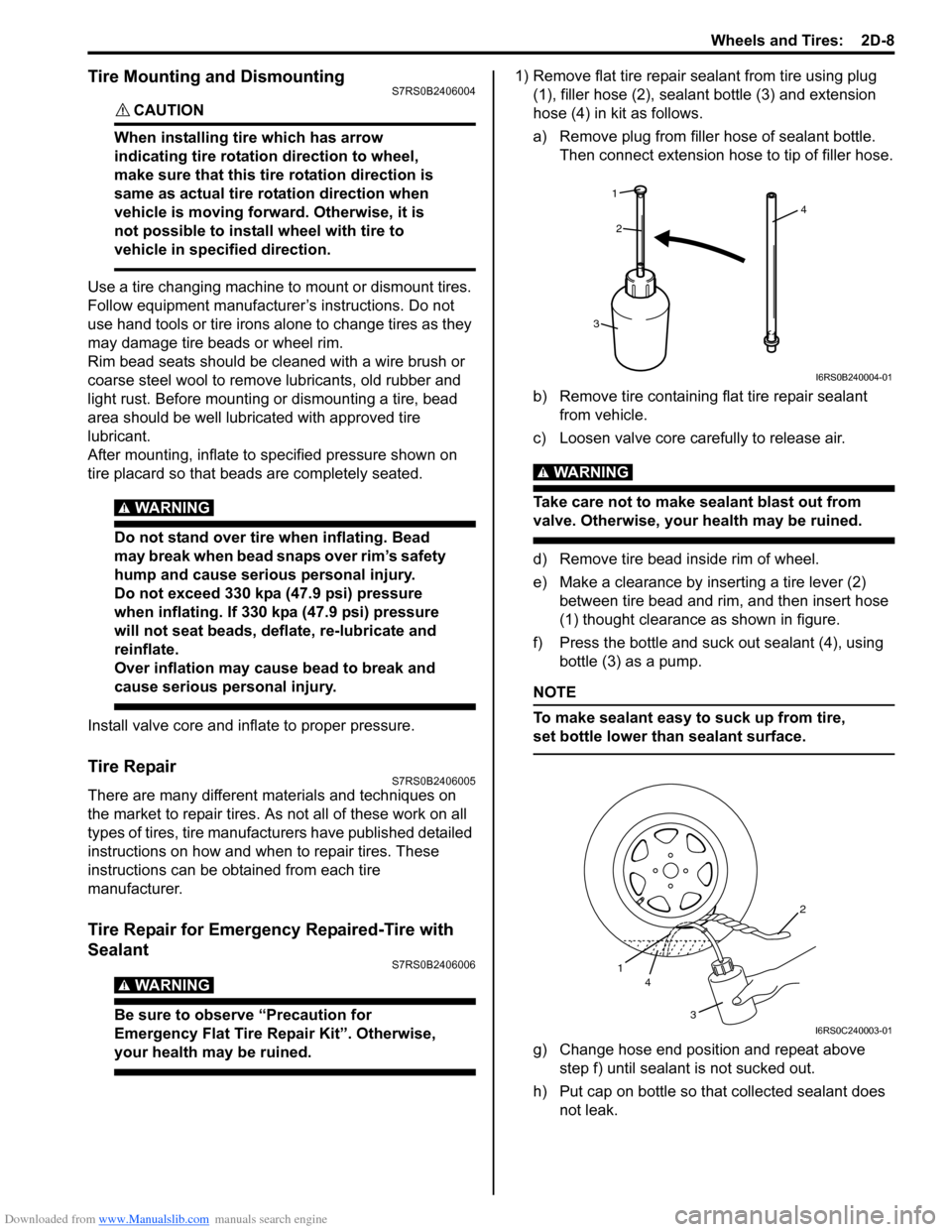
1) Remove flat tire repair sealant from tire using plug (1), filler hose (2), sealant bottle (3) and extension
hose (4) in kit as follows.
a) Remove plug from fille r hose of sealant bottle.
Then connect ext ension hose to tip of filler hose.
b) Remove tire containing flat tire repair sealant from vehicle.
c) Loosen valve core carefully to release air.
WARNING!
Take care not to make sealant blast out from
valve. Otherwise, your health may be ruined.
d) Remove tire bead inside rim of wheel.
e) Make a clearance by inserting a tire lever (2) between tire bead and rim, and then insert hose
(1) thought clearance as shown in figure.
f) Press the bottle and suck out sealant (4), using bottle (3) as a pump.
NOTE
To make sealant easy to suck up from tire,
set bottle lower than sealant surface.
g) Change hose end position and repeat above step f) until sealant is not sucked out.
h) Put cap on bottle so that collected sealant does not leak.
4
1
2
3
I6RS0B240004-01
1 4
3 2
I6RS0C240003-01
Page 518 of 1496
Downloaded from www.Manualslib.com manuals search engine 4B-2 Front Brakes:
Front Disc Brake Pad On-Vehicle InspectionS7RS0B4206002
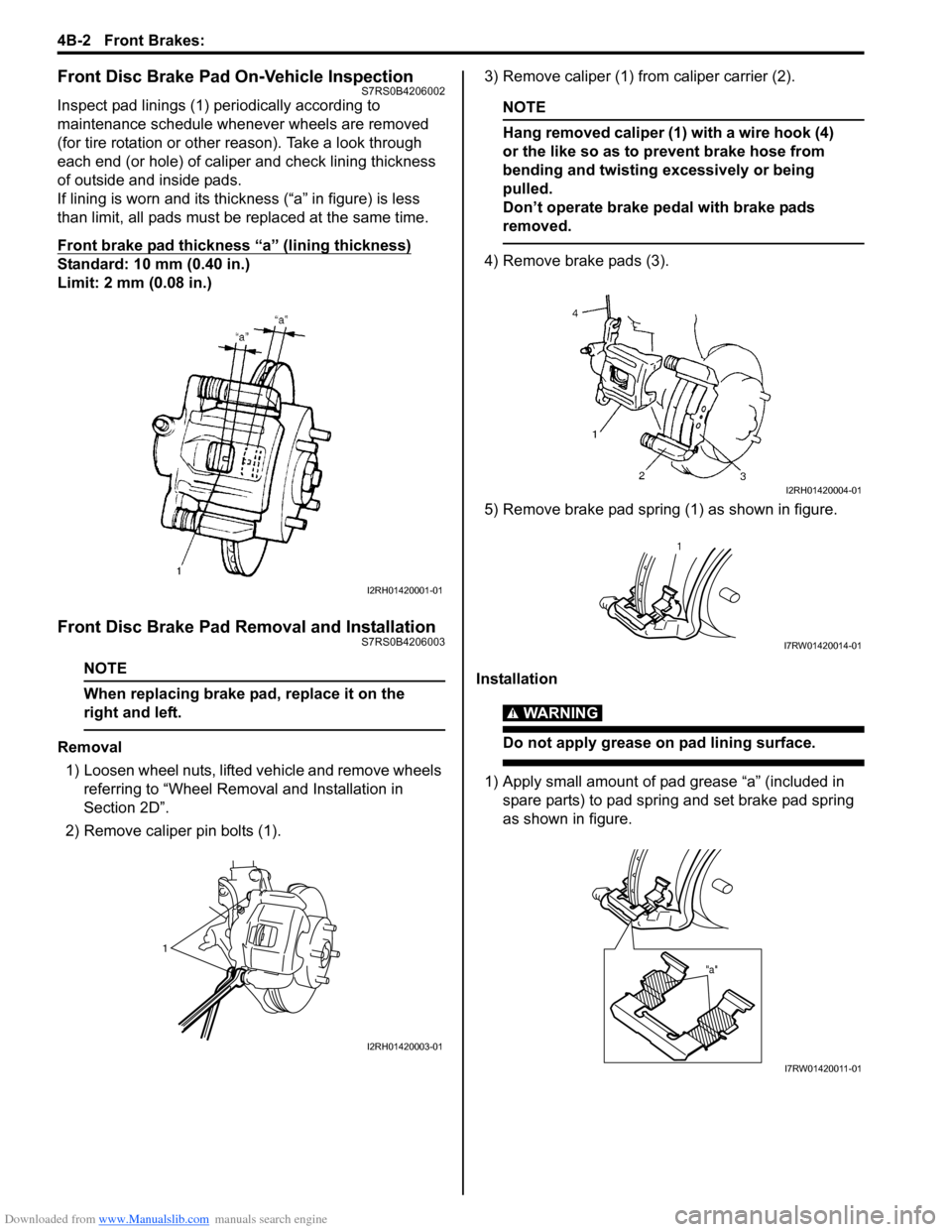
Inspect pad linings (1) periodically according to
maintenance schedule whenever wheels are removed
(for tire rotation or other reason). Take a look through
each end (or hole) of caliper and check lining thickness
of outside and inside pads.
If lining is worn and its thic kness (“a” in figure) is less
than limit, all pads must be replaced at the same time.
Front brake pad thickness “a” (lining thickness)
Standard: 10 mm (0.40 in.)
Limit: 2 mm (0.08 in.)
Front Disc Brake Pad Removal and InstallationS7RS0B4206003
NOTE
When replacing brake pad, replace it on the
right and left.
Removal
1) Loosen wheel nuts, lifted vehicle and remove wheels referring to “Wheel Remova l and Installation in
Section 2D”.
2) Remove caliper pin bolts (1). 3) Remove caliper (1) from caliper carrier (2).
NOTE
Hang removed caliper (1) with a wire hook (4)
or the like so as to prevent brake hose from
bending and twisting excessively or being
pulled.
Don’t operate brake pedal with brake pads
removed.
4) Remove brake pads (3).
5) Remove brake pad spring (1) as shown in figure.
Installation
WARNING!
Do not apply grease on pad lining surface.
1) Apply small amount of pad grease “a” (included in spare parts) to pad spring and set brake pad spring
as shown in figure.
I2RH01420001-01
1
I2RH01420003-01
I2RH01420004-01
1
I7RW01420014-01
"a"
I7RW01420011-01
Page 522 of 1496
Downloaded from www.Manualslib.com manuals search engine 4B-6 Front Brakes:
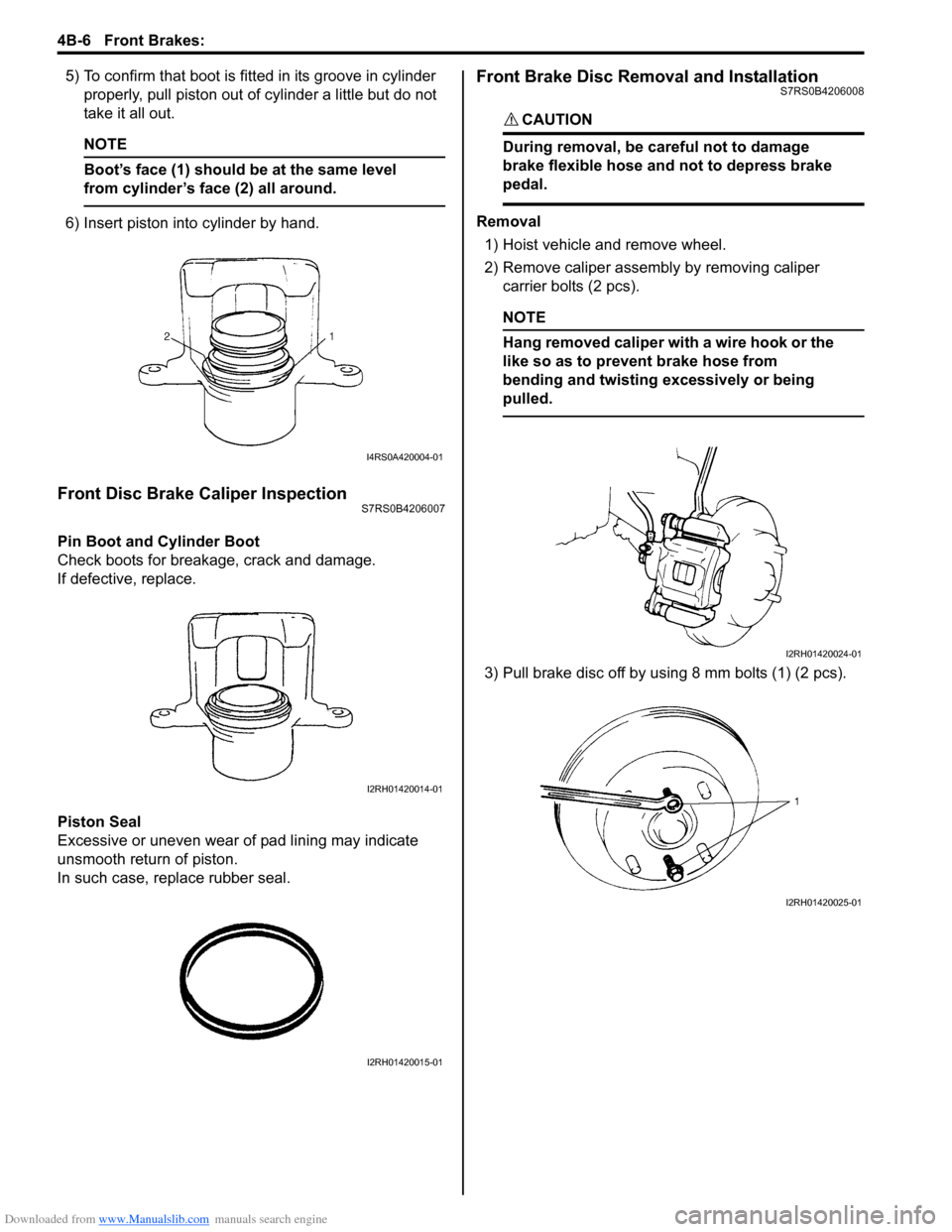
5) To confirm that boot is fitted in its groove in cylinder
properly, pull piston out of cylinder a little but do not
take it all out.
NOTE
Boot’s face (1) should be at the same level
from cylinder’s face (2) all around.
6) Insert piston into cylinder by hand.
Front Disc Brake Caliper InspectionS7RS0B4206007
Pin Boot and Cylinder Boot
Check boots for breakage, crack and damage.
If defective, replace.
Piston Seal
Excessive or uneven wear of pad lining may indicate
unsmooth return of piston.
In such case, replace rubber seal.
Front Brake Disc Removal and InstallationS7RS0B4206008
CAUTION!
During removal, be care ful not to damage
brake flexible hose and not to depress brake
pedal.
Removal
1) Hoist vehicle and remove wheel.
2) Remove caliper assembly by removing caliper carrier bolts (2 pcs).
NOTE
Hang removed caliper with a wire hook or the
like so as to prevent brake hose from
bending and twisting excessively or being
pulled.
3) Pull brake disc off by using 8 mm bolts (1) (2 pcs).
I4RS0A420004-01
I2RH01420014-01
I2RH01420015-01
I2RH01420024-01
I2RH01420025-01
Page 526 of 1496
Downloaded from www.Manualslib.com manuals search engine 4C-2 Rear Brakes:
Rear Disc Brake Pad Removal and InstallationS7RS0B4306002
NOTE
When replacing brake pad, replace it on the
right and left.
Removal1) Hoist vehicle and remove wheel.
2) Release parking brake lever.
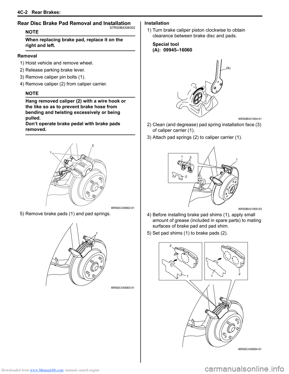
3) Remove caliper pin bolts (1).
4) Remove caliper (2) from caliper carrier.
NOTE
Hang removed caliper (2) with a wire hook or
the like so as to prevent brake hose from
bending and twisting excessively or being
pulled.
Don’t operate brake pedal with brake pads
removed.
5) Remove brake pads (1) and pad springs. Installation
1) Turn brake caliper piston clockwise to obtain clearance between brake disc and pads.
Special tool
(A): 09945–16060
2) Clean (and degrease) pad spring installation face (3) of caliper carrier (1).
3) Attach pad springs (2) to caliper carrier (1).
4) Before installing brake p ad shims (1), apply small
amount of grease (included in spare parts) to mating
surfaces of brake pad and pad shim.
5) Set pad shims (1) to brake pads (2).
1 2
I6RS0C430002-01
1
I6RS0C430003-01
(A)
I6RS0B431004-01
113
2
I6RS0B431005-03
2
1
1 2
I6RS0C430004-01
Page 533 of 1496
Downloaded from www.Manualslib.com manuals search engine Rear Brakes: 4C-9
Rear Brake Disc Removal and InstallationS7RS0B4306008
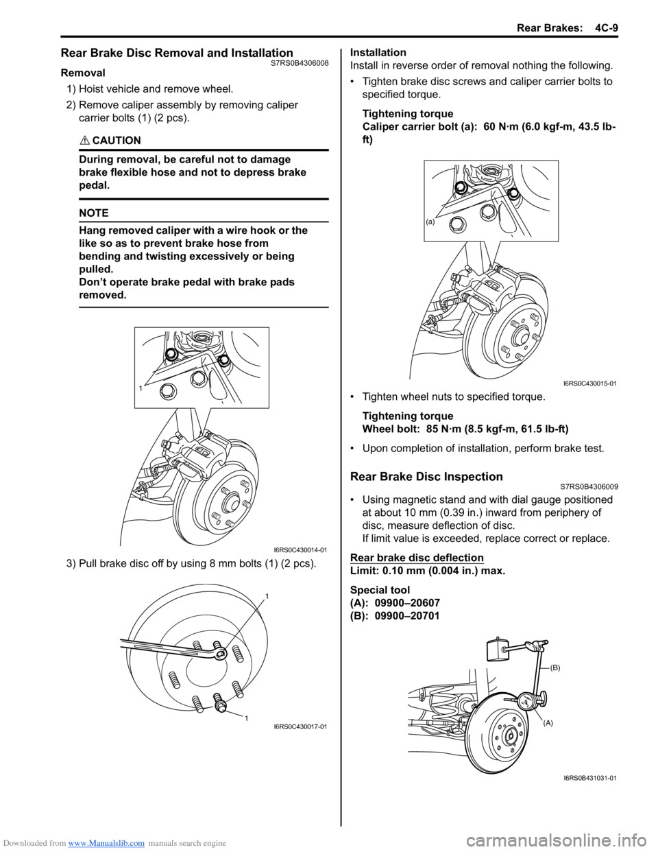
Removal1) Hoist vehicle and remove wheel.
2) Remove caliper assembly by removing caliper
carrier bolts (1) (2 pcs).
CAUTION!
During removal, be ca reful not to damage
brake flexible hose and not to depress brake
pedal.
NOTE
Hang removed caliper with a wire hook or the
like so as to prevent brake hose from
bending and twisting excessively or being
pulled.
Don’t operate brake pedal with brake pads
removed.
3) Pull brake disc off by using 8 mm bolts (1) (2 pcs). Installation
Install in reverse order of removal nothing the following.
• Tighten brake disc screws and caliper carrier bolts to
specified torque.
Tightening torque
Caliper carrier bolt (a): 60 N·m (6.0 kgf-m, 43.5 lb-
ft)
• Tighten wheel nuts to specified torque. Tightening torque
Wheel bolt: 85 N·m (8.5 kgf-m, 61.5 lb-ft)
• Upon completion of installation, perform brake test.
Rear Brake Disc InspectionS7RS0B4306009
• Using magnetic stand and with dial gauge positioned at about 10 mm (0.39 in.) inward from periphery of
disc, measure deflection of disc.
If limit value is exceeded, replace correct or replace.
Rear brake disc deflection
Limit: 0.10 mm (0.004 in.) max.
Special tool
(A): 09900–20607
(B): 09900–20701
1
I6RS0C430014-01
1 1I6RS0C430017-01
(a)
I6RS0C430015-01
(B)
(A)
I6RS0B431031-01
Page 538 of 1496
Downloaded from www.Manualslib.com manuals search engine 4D-3 Parking Brake:
6) Release parking brake lever and then make sure that there is no drag in rear wheel.
If there is, repeats go to step 2).
7) Make sure that the number of notch is between 4 and 9 when operating parking brake lever.
8) If the number of notch is not between 4 and 9, replace parking brake cable and/or inspect rear
brake caliper.
Parking brake stroke
When lever is pulled up at 200 N (20kg, 44lbs) : 4
to 9 notches
Parking Brake Cable Removal and InstallationS7RS0B4406002
Removal
NOTE
When it is necessary to remove both right
and left parking brake cables, repeat below
steps 2) and 5) on right and left wheels.
1) Hoist vehicle.
2) Remove wheel.
3) Disconnect parking brake cable from equalizer (parking brake lever) and clamps.
4) Disconnect parking brake cable from lever referring to “Rear Disc Brake Caliper Removal and Installation
in Section 4C”.
5) Remove parking brake cable and parking cable bracket.
Installation
Install it by reversing removal procedure, noting the
following points.
• Install clamps properly referring to “Parking Brake Cable Construction”.
• Tighten bolts and nuts to specified torque referring to “Parking Brake Cable Construction”.
Tightening torque
Parking brake lever bolt: 25 N·m (2.5 kgf-m, 18.0
lb-ft)
Parking cable clamp bolt: 11 N·m (1.1 kgf-m, 8.0
lb-ft)
Parking cable bracket bolt: 25 N·m (2.5 kgf-m,
18.0 lb-ft)
• Adjust parking brake cable. Refer to “Parking Brake Inspection and Adjustment”.
• Check brake disc for dragging and brake system for proper performance. Brake test should be performed.
Parking Brake Lever Removal and InstallationS7RS0B4406003
Removal
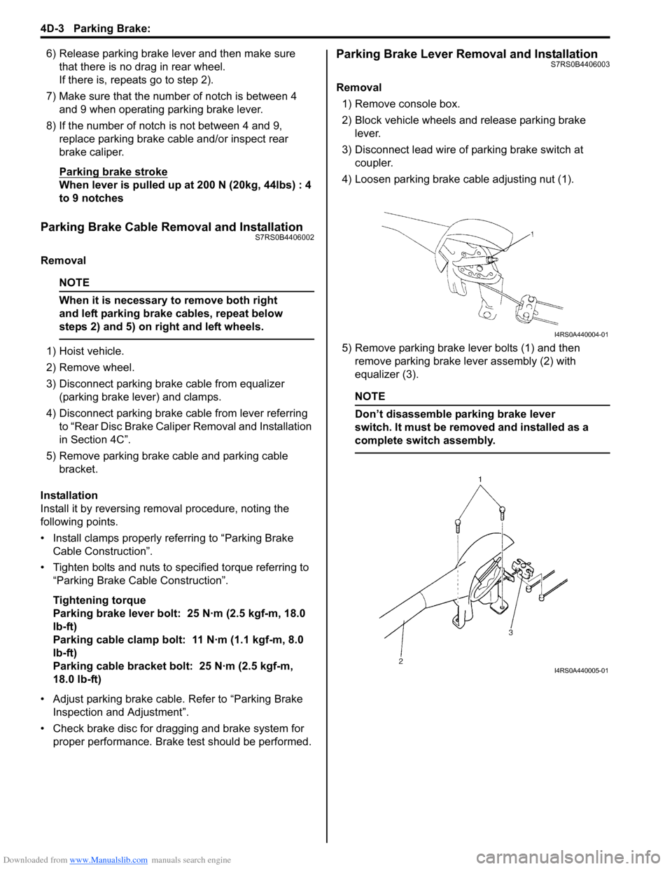
1) Remove console box.
2) Block vehicle wheels and release parking brake lever.
3) Disconnect lead wire of parking brake switch at coupler.
4) Loosen parking brake cable adjusting nut (1).
5) Remove parking brake lever bolts (1) and then remove parking brake lever assembly (2) with
equalizer (3).
NOTE
Don’t disassemble parking brake lever
switch. It must be removed and installed as a
complete switch assembly.
I4RS0A440004-01
I4RS0A440005-01
Page 545 of 1496
Downloaded from www.Manualslib.com manuals search engine ABS: 4E-6
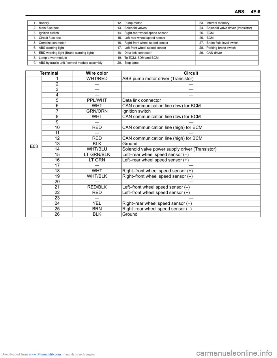
1. Battery12. Pump motor23. Internal memory
2. Main fuse box 13. Solenoid valves24. Solenoid valve driver (transistor)
3. Ignition switch 14. Right-rear wheel speed sensor25. ECM
4. Circuit fuse box 15. Left-rear wheel speed sensor26. BCM
5. Combination meter 16. Right-front wheel speed sensor27. Brake fluid level switch
6. ABS warning light 17. Left-front wheel speed sensor28. Parking brake switch
7. EBD warning light (Brake warning light) 18. Data link connector29. CAN driver
8. Lamp driver module 19. To ECM, SDM and BCM
9. ABS hydraulic unit / control module assembly 20. Stop lamp
Terminal Wire color Circuit
E03 1
WHT/RED ABS pump motor driver (Transistor)
2— —
3— —
4— —
5 PPL/WHT Data link connector
6 WHT CAN communication line (low) for BCM
7 GRN/ORN Ignition switch
8 WHT CAN communication line (low) for ECM
9— —
10 RED CAN communication line (high) for ECM
11 — —
12 RED CAN communication line (high) for BCM
13 BLK Ground
14 WHT/BLU Solenoid valve power supply driver (Transistor)
15 LT GRN/BLK Left–rear wheel speed sensor (–)
16 LT GRN Left–rear wheel speed sensor (+)
17 — —
18 WHT Right–front wheel speed sensor (+)
19 WHT/BLK Right–front wheel speed sensor (–)
20 — —
21 RED/BLK Left–front wheel speed sensor (–)
22 RED Left–front wheel speed sensor (+)
23 — —
24 YEL Right–rear wheel speed sensor (+)
25 BRN Right–rear wheel speed sensor (–)
26 BLK Ground
Page 549 of 1496
Downloaded from www.Manualslib.com manuals search engine ABS: 4E-10
Problem symptom confirmation
Check if what the customer claimed in “Customer
Questionnaire” is actually found in the vehicle and if that
symptom is found, whether it is identified as a failure.
(This step should be shared with the customer if
possible.) Check warning lights related to brake system
referring to “EBD Warning Light (Brake Warning Light)
Check” and “ABS Warning Light Check”.
DTC check, record and clearance
Perform “DTC Check” proced ure, record it and then
clear it referring to “DTC Clearance”.
Recheck DTC referring to “DTC Check”.
When DTC which is recorded at DTC check procedure is
detected again after performi ng DTC clearance, go to
“Step 4: ABS Check: ” to proceed the diagnosis.
When DTC which is recorded at DTC check procedure is
not indicated anymore after performing DTC clearance,
ABS control module does not perform the system
diagnosis, or temporary abnormality may occur,
therefore go to “Step 2: Driving Test: ” to proceed the
diagnosis.
Step 2: Driving Test
Test drive the vehicle at 40 km/h for more than a minute
and check if any trouble symptom (such as abnormal
lighting of ABS warn ing light) exists.
If the malfunction DTC is co nfirmed again at ignition
switch ON, driving test as described is not necessary.
Proceed to Step 3.
Step 3: DTC Check
Recheck DTC referring to “DTC Check”.
Step 4: ABS Check
According to ABS Check for the DTC confirmation in
Step 3, locate the cause of the trouble, namely in a
sensor, switch, wire harness, connector, actuator
assembly or other part and repair or replace faulty parts.
Step 5: Brakes Diagnosis
Check the parts or system suspected as a possible
cause referring to “Brakes Symptom Diagnosis in
Section 4A” and based on symptoms appearing on the
vehicle (symptom obtained through Steps 1 and 2 and
repair or replace faulty parts, if any).
Step 6: Check for Intermittent Problem
Check parts where an intermittent trouble is easy to
occur (e.g., wire harness, con nector, etc.), referring to
“Intermittent and Poor Connection Inspection in Section
00” and related circuit of trouble code recorded in Step 1
to 3.
Step 7: Final Confirmation Test
Confirm that the problem symptom has gone and the
ABS is free from any abnormal conditions. If what has
been repaired is related to the malfunction DTC, clear
the DTC once referring to “DTC Clearance” and perform
test driving and confirm that no DTC is indicated.ABS Warning Light CheckS7RS0B4504002
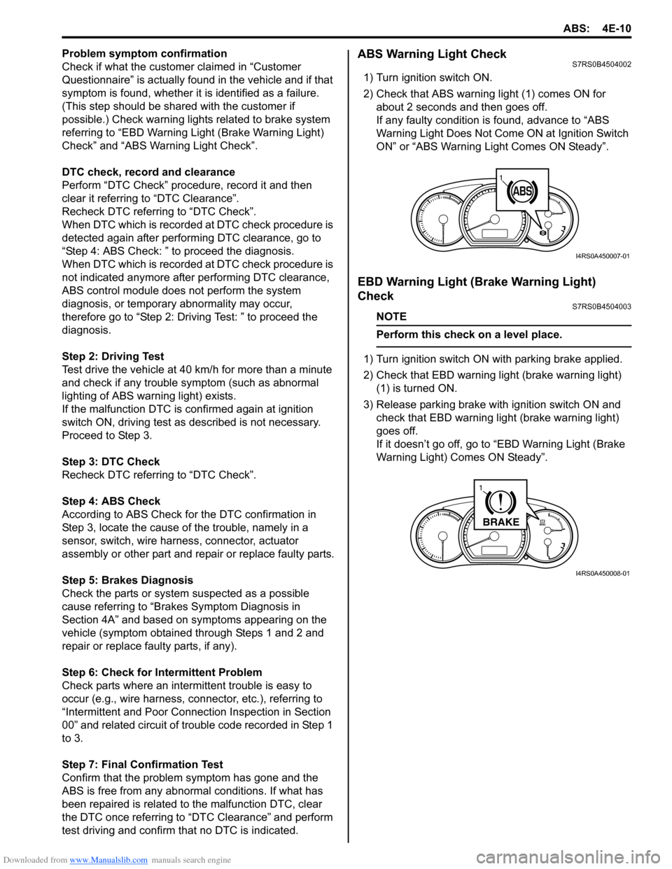
1) Turn ignition switch ON.
2) Check that ABS warning light (1) comes ON for
about 2 seconds and then goes off.
If any faulty condition is found, advance to “ABS
Warning Light Does Not Come ON at Ignition Switch
ON” or “ABS Warning Light Comes ON Steady”.
EBD Warning Light (Brake Warning Light)
Check
S7RS0B4504003
NOTE
Perform this check on a level place.
1) Turn ignition switch ON with parking brake applied.
2) Check that EBD warning lig ht (brake warning light)
(1) is turned ON.
3) Release parking brake with ignition switch ON and check that EBD warning lig ht (brake warning light)
goes off.
If it doesn’t go off, go to “EBD Warning Light (Brake
Warning Light) Comes ON Steady”.
11
I4RS0A450007-01
BRAKE
1
I4RS0A450008-01
Page 553 of 1496
Downloaded from www.Manualslib.com manuals search engine ABS: 4E-14
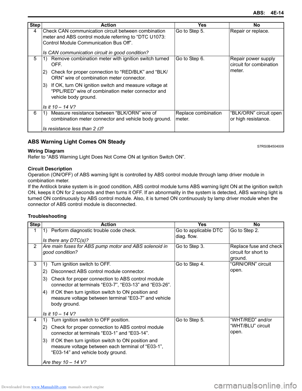
ABS Warning Light Comes ON SteadyS7RS0B4504009
Wiring Diagram
Refer to “ABS Warning Light Does Not Come ON at Ignition Switch ON”.
Circuit Description
Operation (ON/OFF) of ABS wa rning light is controlled by ABS contro l module through lamp driver module in
combination meter.
If the Antilock brake system is in good condition, ABS control module turns ABS warning lig ht ON at the ignition switch
ON, keeps it ON for 2 seconds and then turns it OFF. If an abnormality in the system is detected, ABS warning light is
turned ON continuously by ABS c ontrol module. Also, it is turned ON continuously by la mp driver module when the
connector of ABS control module is disconnected.
Troubleshooting 4 Check CAN communication circuit between combination
meter and ABS control module referring to “DTC U1073:
Control Module Communication Bus Off”.
Is CAN communication circuit in good condition? Go to Step 5.
Repair or replace.
5 1) Remove combination meter wit h ignition switch turned
OFF.
2) Check for proper connection to “RED/BLK” and “BLK/ ORN” wire of combinat ion meter connector.
3) If OK, turn ON ignition switch and measure voltage at “PPL/RED” wire of combi nation meter connector and
vehicle body ground.
Is it 10 – 14 V? Go to Step 6.
Repair power supply
circuit for combination
meter.
6 1) Measure resistance between “BLK/ORN” wire of combination meter connector and vehicle body ground.
Is resistance less than 2
Ω? Replace combination
meter.
“BLK/ORN” circuit open
or high resistance.
Step Action Yes No
Step
Action YesNo
1 1) Perform diagnostic trouble code check.
Is there any DTC(s)? Go to applicable DTC
diag. flow.
Go to Step 2.
2 Are main fuses for ABS pump motor and ABS solenoid in
good condition? Go to Step 3.
Replace fuse and check
circuit for short to
ground.
3 1) Turn ignition switch to OFF.
2) Disconnect ABS control module connector.
3) Check for proper connection to ABS control module connector at terminals “E03-7”, “E03-13” and “E03-26”.
4) If OK then turn ignition switch to ON position and measure voltage between terminal “E03-7” and vehicle
body ground.
Is it 10 – 14 V? Go to Step 4.
“GRN/ORN” circuit
open.
4 1) Turn ignition switch to OFF position. 2) Check for proper connection to ABS control module connector at terminals “E03-1” and “E03-14”.
3) If OK then turn ignition switch to ON position and measure voltage between each terminal of “E03-1”,
“E03-14” and vehicle body ground.
Are they 10 – 14 V? Go to Step 5.
“WHT/RED” and/or
“WHT/BLU” circuit
open.
Page 555 of 1496
Downloaded from www.Manualslib.com manuals search engine ABS: 4E-16
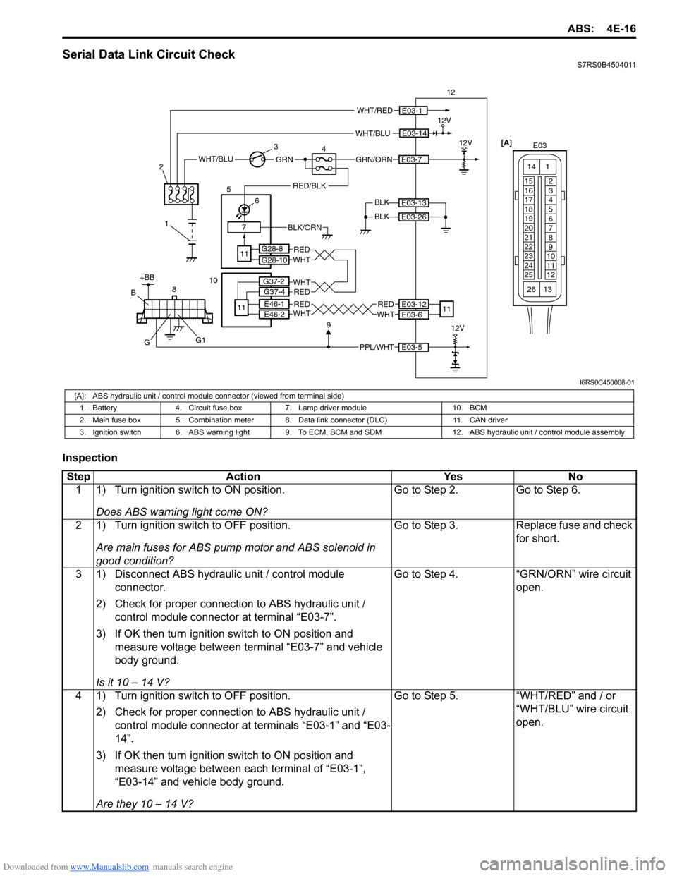
Serial Data Link Circuit CheckS7RS0B4504011
Inspection
WHT/BLU
BLK12V
12
BLK
E03-14
E03-13
E03-26
WHT/RED
GRN/ORNE03-7WHT/BLUGRN
1
2
3
47
RED/BLK
6
5
11
E03-112V
[A]
E03
15
16
17
18
19
20
21
22
23
24
25 2
3
4
5
6
7
8
9
10
11
12
1
13
14
26
BLK/ORN
PPL/WHT
8E03-5
912V
+BB
G
B
G1
E03-12
E03-6
REDWHT
11
G28-8
G28-10
REDWHTE46-1
E46-2RED
RED
WHT
WHT
10
11
G37-2
G37-4
I6RS0C450008-01
[A]: ABS hydraulic unit / control module connector (viewed from terminal side)
1. Battery 4. Circuit fuse box 7. Lamp driver module 10. BCM
2. Main fuse box 5. Combination meter 8. Data link connector (DLC) 11. CAN driver
3. Ignition switch 6. ABS warning light 9. To ECM, BCM and SDM 12. ABS hydraulic unit / control module assembly
Step Action YesNo
1 1) Turn ignition switch to ON position.
Does ABS warning light come ON? Go to Step 2.
Go to Step 6.
2 1) Turn ignition switch to OFF position. Are main fuses for ABS pump motor and ABS solenoid in
good condition? Go to Step 3.
Replace fuse and check
for short.
3 1) Disconnect ABS hydraulic unit / control module connector.
2) Check for proper connection to ABS hydraulic unit / control module connector at terminal “E03-7”.
3) If OK then turn ignition switch to ON position and measure voltage between terminal “E03-7” and vehicle
body ground.
Is it 10 – 14 V? Go to Step 4.
“GRN/ORN” wire circuit
open.
4 1) Turn ignition switch to OFF position. 2) Check for proper connection to ABS hydraulic unit / control module connector at terminals “E03-1” and “E03-
14”.
3) If OK then turn ignition switch to ON position and measure voltage between each terminal of “E03-1”,
“E03-14” and vehicle body ground.
Are they 10 – 14 V? Go to Step 5.
“WHT/RED” and / or
“WHT/BLU” wire circuit
open.