Request switch SUZUKI SWIFT 2008 2.G Service User Guide
[x] Cancel search | Manufacturer: SUZUKI, Model Year: 2008, Model line: SWIFT, Model: SUZUKI SWIFT 2008 2.GPages: 1496, PDF Size: 34.44 MB
Page 667 of 1496
Downloaded from www.Manualslib.com manuals search engine Automatic Transmission/Transaxle: 5A-23
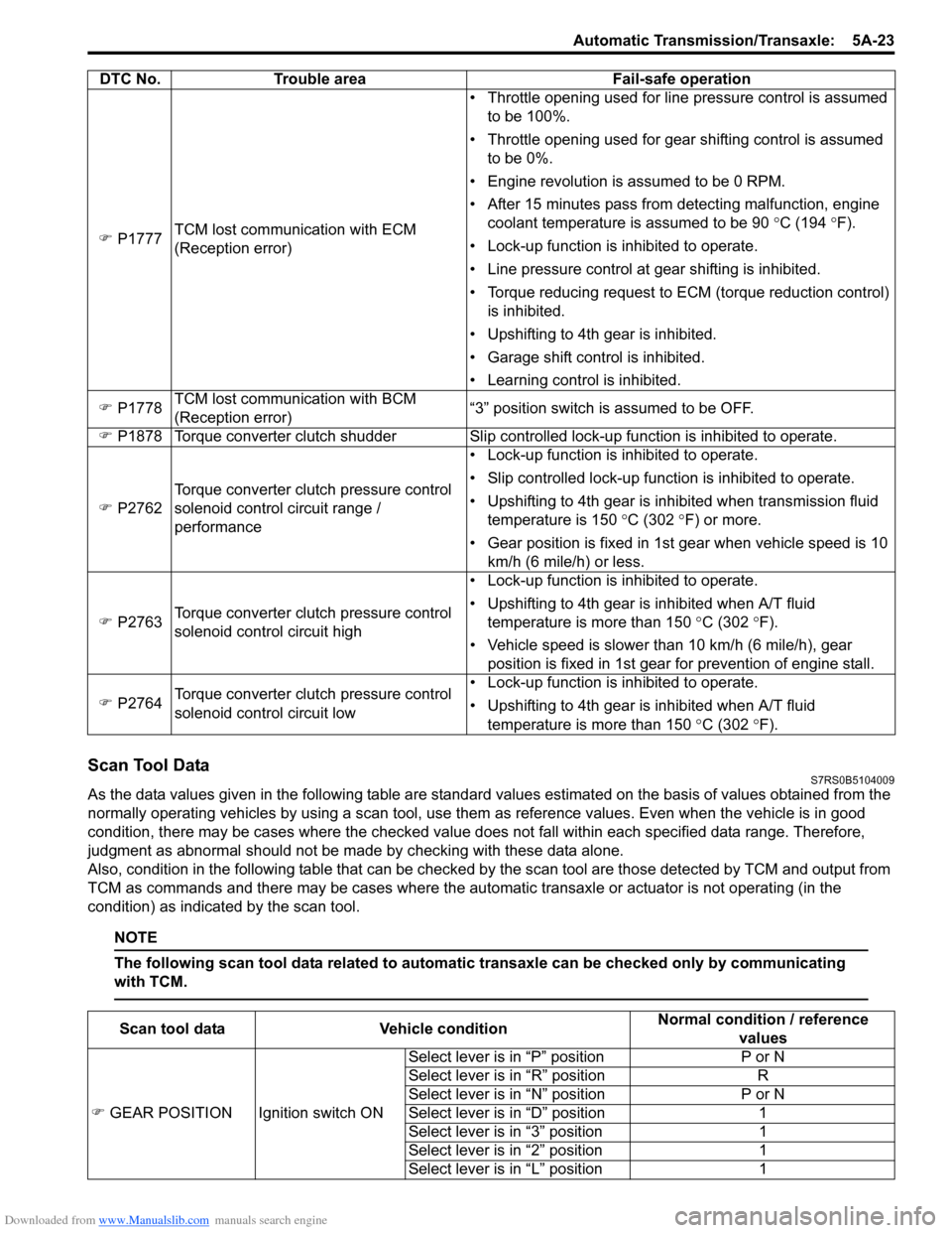
Scan Tool DataS7RS0B5104009
As the data values given in the following table are standard values estimated on the basis of values obtained from the
normally operating vehicles by using a scan tool, use them as reference values. Even when the vehicle is in good
condition, there may be cases where the checked value does not fall within each specified data range. Therefore,
judgment as abnormal should not be made by checking with these data alone.
Also, condition in the following table that can be checked by the scan tool are those detected by TCM and output from
TCM as commands and there may be cases where the auto matic transaxle or actuator is not operating (in the
condition) as indicated by the scan tool.
NOTE
The following scan tool data related to automatic transaxle can be checked only by communicating
with TCM.
�) P1777 TCM lost communication with ECM
(Reception error) • Throttle opening used for line pressure control is assumed
to be 100%.
• Throttle opening used for gear shifting control is assumed to be 0%.
• Engine revolution is assumed to be 0 RPM.
• After 15 minutes pass from detecting malfunction, engine coolant temperature is assumed to be 90 °C (194 °F).
• Lock-up function is inhibited to operate.
• Line pressure control at gear shifting is inhibited.
• Torque reducing request to ECM (torque reduction control) is inhibited.
• Upshifting to 4th gear is inhibited.
• Garage shift control is inhibited.
• Learning control is inhibited.
�) P1778 TCM lost communication with BCM
(Reception error) “3” position switch is assumed to be OFF.
�) P1878 Torque converter clutch shudder Slip contro lled lock-up function is inhibited to operate.
�) P2762 Torque converter clutch pressure control
solenoid control circuit range /
performance • Lock-up function is inhibited to operate.
• Slip controlled lock-up function is inhibited to operate.
• Upshifting to 4th gear is inhibited when transmission fluid
temperature is 150 °C (302 ° F) or more.
• Gear position is fixed in 1st gear when vehicle speed is 10 km/h (6 mile/h) or less.
�) P2763 Torque converter clutch pressure control
solenoid control circuit high • Lock-up function is inhibited to operate.
• Upshifting to 4th gear is inhibited when A/T fluid
temperature is more than 150 °C (302 °F).
• Vehicle speed is slower than 10 km/h (6 mile/h), gear position is fixed in 1st gear for prevention of engine stall.
�) P2764 Torque converter clutch pressure control
solenoid control circuit low • Lock-up function is inhibited to operate.
• Upshifting to 4th gear is inhibited when A/T fluid
temperature is more than 150 °C (302 °F).
DTC No. Trouble area Fail-safe operation
Scan tool data
Vehicle condition Normal condition / reference
values
�) GEAR POSITION Ignition switch ON Select lever is in “P” position
P or N
Select lever is in “R” position R
Select lever is in “N” position P or N
Select lever is in “D” position 1
Select lever is in “3” position 1
Select lever is in “2” position 1
Select lever is in “L” position 1
Page 669 of 1496
Downloaded from www.Manualslib.com manuals search engine Automatic Transmission/Transaxle: 5A-25
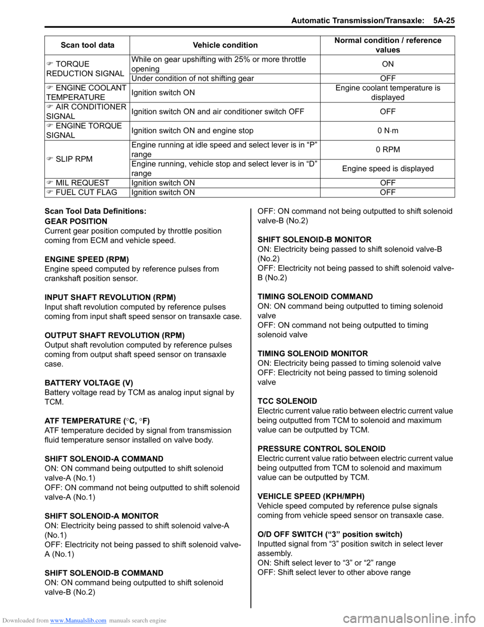
Scan Tool Data Definitions:
GEAR POSITION
Current gear position computed by throttle position
coming from ECM and vehicle speed.
ENGINE SPEED (RPM)
Engine speed computed by reference pulses from
crankshaft position sensor.
INPUT SHAFT REVOLUTION (RPM)
Input shaft revolution computed by reference pulses
coming from input shaft speed sensor on transaxle case.
OUTPUT SHAFT REVOLUTION (RPM)
Output shaft revolution computed by reference pulses
coming from output shaft speed sensor on transaxle
case.
BATTERY VOLTAGE (V)
Battery voltage read by TCM as analog input signal by
TCM.
ATF TEMPERATURE (°C, °F)
ATF temperature decided by signal from transmission
fluid temperature sensor installed on valve body.
SHIFT SOLENOID-A COMMAND
ON: ON command being outputted to shift solenoid
valve-A (No.1)
OFF: ON command not being outputted to shift solenoid
valve-A (No.1)
SHIFT SOLENOID-A MONITOR
ON: Electricity being passed to shift solenoid valve-A
(No.1)
OFF: Electricity not being passed to shift solenoid valve-
A (No.1)
SHIFT SOLENOID-B COMMAND
ON: ON command being outputted to shift solenoid
valve-B (No.2) OFF: ON command not being outputted to shift solenoid
valve-B (No.2)
SHIFT SOLENOID-B MONITOR
ON: Electricity being passed to shift solenoid valve-B
(No.2)
OFF: Electricity not being passed to shift solenoid valve-
B (No.2)
TIMING SOLENOID COMMAND
ON: ON command being outputted to timing solenoid
valve
OFF: ON command not being outputted to timing
solenoid valve
TIMING SOLENOID MONITOR
ON: Electricity being passed to timing solenoid valve
OFF: Electricity not being passed to timing solenoid
valve
TCC SOLENOID
Electric current value ratio between electric current value
being outputted from TCM to solenoid and maximum
value can be outputted by TCM.
PRESSURE CONTROL SOLENOID
Electric current value ratio between electric current value
being outputted from TCM to solenoid and maximum
value can be outputted by TCM.
VEHICLE SPEED (KPH/MPH)
Vehicle speed computed by reference pulse signals
coming from vehicle speed sensor on transaxle case.
O/D OFF SWITCH (“3” position switch)
Inputted signal from “3” position switch in select lever
assembly.
ON: Shift select lever to “3” or “2” range
OFF: Shift select lever to other above range
�)
TORQUE
REDUCTION SIGNAL While on gear upshifting with 25% or more throttle
opening
ON
Under condition of not shifting gear OFF
�) ENGINE COOLANT
TEMPERATURE Ignition switch ON Engine coolant temperature is
displayed
�) AIR CONDITIONER
SIGNAL Ignition switch ON and air conditioner switch OFF OFF
�) ENGINE TORQUE
SIGNAL Ignition switch ON and engine stop 0 N
⋅m
�) SLIP RPM Engine running at idle speed
and select lever is in “P”
range 0 RPM
Engine running, vehicle stop and select lever is in “D”
range Engine speed is displayed
�) MIL REQUEST Ignition switch ON OFF
�) FUEL CUT FLAG Ignition switch ON OFFScan tool data Vehicle condition
Normal condition / reference
values
Page 670 of 1496
Downloaded from www.Manualslib.com manuals search engine 5A-26 Automatic Transmission/Transaxle:
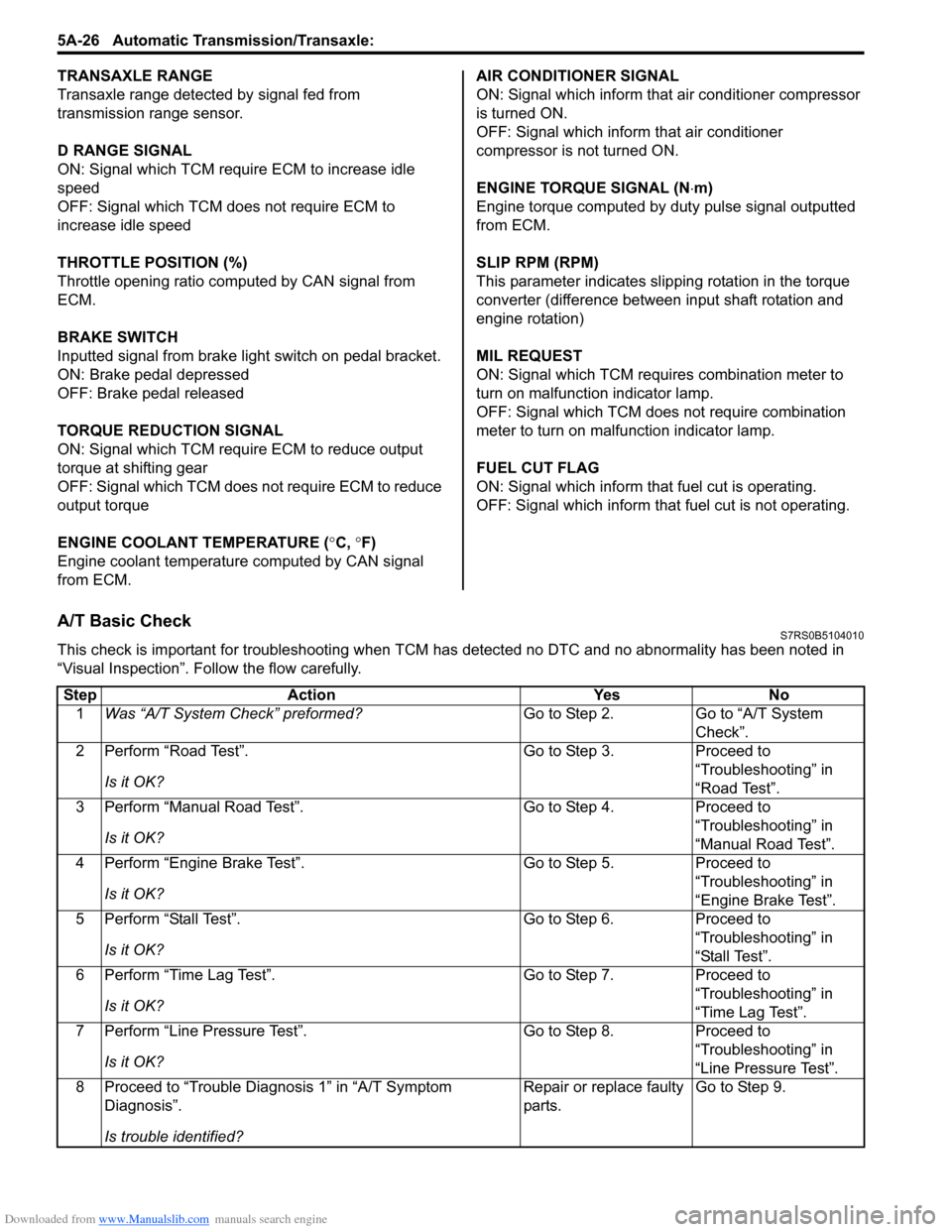
TRANSAXLE RANGE
Transaxle range detected by signal fed from
transmission range sensor.
D RANGE SIGNAL
ON: Signal which TCM require ECM to increase idle
speed
OFF: Signal which TCM does not require ECM to
increase idle speed
THROTTLE POSITION (%)
Throttle opening ratio computed by CAN signal from
ECM.
BRAKE SWITCH
Inputted signal from brake light switch on pedal bracket.
ON: Brake pedal depressed
OFF: Brake pedal released
TORQUE REDUCTION SIGNAL
ON: Signal which TCM require ECM to reduce output
torque at shifting gear
OFF: Signal which TCM does not require ECM to reduce
output torque
ENGINE COOLANT TEMPERATURE ( °C, °F)
Engine coolant temperature computed by CAN signal
from ECM. AIR CONDITIONER SIGNAL
ON: Signal which inform that air conditioner compressor
is turned ON.
OFF: Signal which inform that air conditioner
compressor is not turned ON.
ENGINE TORQUE SIGNAL (N
⋅m)
Engine torque computed by duty pulse signal outputted
from ECM.
SLIP RPM (RPM)
This parameter indicates slip ping rotation in the torque
converter (difference between input shaft rotation and
engine rotation)
MIL REQUEST
ON: Signal which TCM requires combination meter to
turn on malfunction indicator lamp.
OFF: Signal which TCM does not require combination
meter to turn on malf unction indicator lamp.
FUEL CUT FLAG
ON: Signal which inform that fuel cut is operating.
OFF: Signal which inform that fuel cut is not operating.
A/T Basic CheckS7RS0B5104010
This check is important for troubleshooting when TCM has detected no DTC and no abnormality has been noted in
“Visual Inspection”. Fo llow the flow carefully.
Step Action YesNo
1 Was “A/T System Check” preformed? Go to Step 2.Go to “A/T System
Check”.
2 Perform “Road Test”.
Is it OK? Go to Step 3.
Proceed to
“Troubleshooting” in
“Road Test”.
3 Perform “Manual Road Test”.
Is it OK? Go to Step 4.
Proceed to
“Troubleshooting” in
“Manual Road Test”.
4 Perform “Engine Brake Test”.
Is it OK? Go to Step 5.
Proceed to
“Troubleshooting” in
“Engine Brake Test”.
5 Perform “Stall Test”.
Is it OK? Go to Step 6.
Proceed to
“Troubleshooting” in
“Stall Test”.
6 Perform “Time Lag Test”.
Is it OK? Go to Step 7.
Proceed to
“Troubleshooting” in
“Time Lag Test”.
7 Perform “Line Pressure Test”.
Is it OK? Go to Step 8.
Proceed to
“Troubleshooting” in
“Line Pressure Test”.
8 Proceed to “Trouble Diag nosis 1” in “A/T Symptom
Diagnosis”.
Is trouble identified? Repair or replace faulty
parts.
Go to Step 9.
Page 1019 of 1496
Downloaded from www.Manualslib.com manuals search engine Air Conditioning System: Automatic Type 7B-71
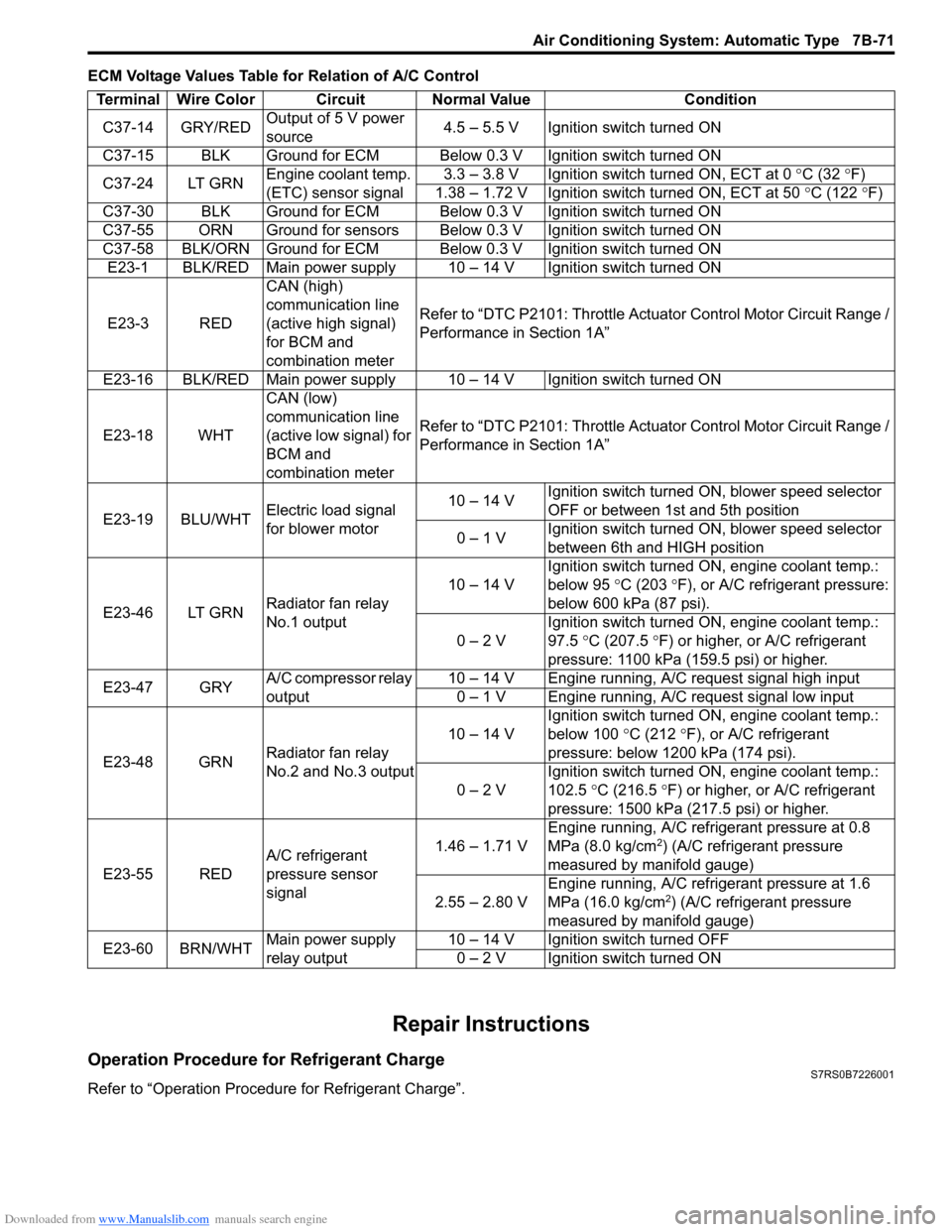
ECM Voltage Values Table for Relation of A/C Control
Repair Instructions
Operation Procedure for Refrigerant ChargeS7RS0B7226001
Refer to “Operation Procedure for Refrigerant Charge”.Terminal Wire Color Circuit Normal Value Condition
C37-14 GRY/RED Output of 5 V power
source 4.5 – 5.5 V Ignition switch turned ON
C37-15 BLK Ground for ECM Below 0.3 V Ignition switch turned ON
C37-24 LT GRN Engine coolant temp.
(ETC) sensor signal 3.3 – 3.8 V Ignition switch turned ON, ECT at 0
°C (32 ° F)
1.38 – 1.72 V Ignition switch turned ON, ECT at 50 °C (122 °F)
C37-30 BLK Ground for ECM Below 0.3 V Ignition switch turned ON
C37-55 ORN Ground for sensors Below 0.3 V Ignition switch turned ON
C37-58 BLK/ORN Ground for ECM Below 0.3 V Ignition switch turned ON E23-1 BLK/RED Main power supply 10 – 14 V Ignition switch turned ON
E23-3 RED CAN (high)
communication line
(active high signal)
for BCM and
combination meterRefer to “DTC P2101: Throttle Actu
ator Control Motor Circuit Range /
Performance in Section 1A”
E23-16 BLK/RED Main power supply 10 – 14 V Ignition switch turned ON
E23-18 WHT CAN (low)
communication line
(active low signal) for
BCM and
combination meterRefer to “DTC P2101: Throttle Actu
ator Control Motor Circuit Range /
Performance in Section 1A”
E23-19 BLU/WHT Electric load signal
for blower motor 10 – 14 V
Ignition switch turned ON, blower speed selector
OFF or between 1st and 5th position
0 – 1 V Ignition switch turned ON, blower speed selector
between 6th and HIGH position
E23-46 LT GRN Radiator fan relay
No.1 output 10 – 14 V
Ignition switch turned ON, engine coolant temp.:
below 95
°C (203 ° F), or A/C refrigerant pressure:
below 600 kPa (87 psi).
0 – 2 V Ignition switch turned ON, engine coolant temp.:
97.5
°C (207.5 °F) or higher, or A/C refrigerant
pressure: 1100 kPa (159.5 psi) or higher.
E23-47 GRY A/C compressor relay
output 10 – 14 V Engine running, A/C request signal high input
0 – 1 V Engine running, A/C request signal low input
E23-48 GRN Radiator fan relay
No.2 and No.3 output 10 – 14 V
Ignition switch turned ON, engine coolant temp.:
below 100
°C (212 °F), or A/C refrigerant
pressure: below 1200 kPa (174 psi).
0 – 2 V Ignition switch turned ON, engine coolant temp.:
102.5
°C (216.5 ° F) or higher, or A/C refrigerant
pressure: 1500 kPa (217.5 psi) or higher.
E23-55 RED A/C refrigerant
pressure sensor
signal 1.46 – 1.71 V
Engine running, A/C refrigerant pressure at 0.8
MPa (8.0 kg/cm
2) (A/C refrigerant pressure
measured by manifold gauge)
2.55 – 2.80 V Engine running, A/C refrigerant pressure at 1.6
MPa (16.0 kg/cm
2) (A/C refrigerant pressure
measured by manifold gauge)
E23-60 BRN/WHT Main power supply
relay output 10 – 14 V Ignition switch turned OFF
0 – 2 V Ignition switch turned ON
Page 1192 of 1496
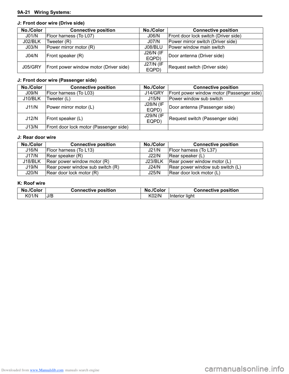
Downloaded from www.Manualslib.com manuals search engine 9A-21 Wiring Systems:
J: Front door wire (Drive side)
J: Front door wire (Passenger side)
J: Rear door wire
K: Roof wireNo./Color Connective position No.
/Color Connective position
J01/N Floor harness (To L07) J06/N Front door lock switch (Driver side)
J02/BLK Tweeter (R) J07/N Power mirror switch (Driver side) J03/N Power mirror motor (R) J08/BLU Power window main switch
J04/N Front speaker (R) J26/N (IF
EQPD) Door antenna (Driver side)
J05/GRY Front power window motor (Driver side) J27/N (IF
EQPD) Request switch (Driver side)
No./Color
Connective position No./ColorConnective position
J09/N Floor harness (To L03) J14/GRY Front power window motor (Passenger side)
J10/BLK Tweeter (L) J15/N Power window sub switch
J11/N Power mirror motor (L) J28/N (IF
EQPD) Door antenna (Passenger side)
J12/N Front speaker (L) J29/N (IF
EQPD) Request switch (Passenger side)
J13/N Front door lock motor (Passenger side)
No./Color Connective position No./ColorConnective position
J16/N Floor harness (To L13) J21/N Floor harness (To L37)
J17/N Rear speaker (R) J22/N Rear speaker (L)
J18/BLK Rear power window motor (R) J23/BLK Rear power window motor (L)
J19/N Rear power window sub switch (R) J24/N Rear power window sub switch (L)
J20/N Rear door lock motor (R) J25/N Rear door lock motor (L)
No./ColorConnective position No./Color Connective position
K01/N J/B K02/N Interior light
Page 1193 of 1496
Downloaded from www.Manualslib.com manuals search engine Wiring Systems: 9A-22
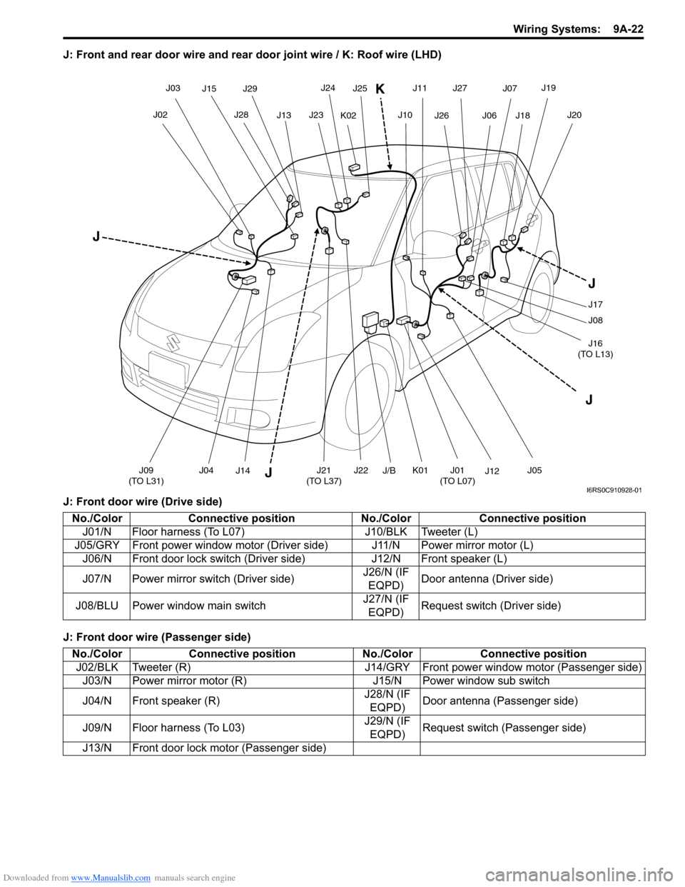
J: Front and rear door wire and rear door joint wire / K: Roof wire (LHD)
J: Front door wire (Drive side)
J: Front door wire (Passenger side)
J04J21
(TO L37)
J02
J03
J13
J15J29
J28 J25J23
J24
JJ09
(TO L31) J22J01
(TO L07)J12
J10J06J18
J19
J20
J J
J17
J08
J16
(TO L13)
J05
J11
J26
J07
J27
J14
J
K02
K
J/BK01
I6RS0C910928-01
No./Color Connective position No./Color Connective position
J01/N Floor harness (To L07) J10/BLK Tweeter (L)
J05/GRY Front power window motor (Driver side) J11/N Power mirror motor (L) J06/N Front door lock switch (Dri ver side)J12/N Front speaker (L)
J07/N Power mirror switch (Driver side) J26/N (IF
EQPD) Door antenna (Driver side)
J08/BLU Power window main switch J27/N (IF
EQPD) Request switch (Driver side)
No./Color
Connective position No./ColorConnective position
J02/BLK Tweeter (R) J14/GRY Front power window motor (Passenger side)
J03/N Power mirror motor (R) J15/N Power window sub switch
J04/N Front speaker (R) J28/N (IF
EQPD) Door antenna (Passenger side)
J09/N Floor harness (To L03) J29/N (IF
EQPD) Request switch (Passenger side)
J13/N Front door lock motor (Passenger side)
Page 1243 of 1496
Downloaded from www.Manualslib.com manuals search engine Wiring Systems: 9A-72
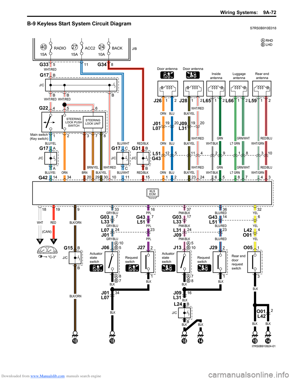
B-9 Keyless Start System Circuit DiagramS7RS0B910E018
BLKBLK
BLK
BLKBLK
YELBLU/REDPNK/BLKPPLGRY/BLU
YELBLU/REDPNK/BLKPPLGRY/BLU
YELBLU/REDPNK/BLKPPLGRY/BLU
G33
KLS
ECM
WHT/RED
WHT/REDWHT/RED
BLU/YEL
WHTRED
ORN
BLU/YEL
"C-3"
WR
G42143420
1819
BLK/ORN
BLK/ORN
9
5
J/B
15A RADIO
40
G348
10A
BACK
24
11
15A
ACC2
27
B
B
B
J/C
G17
B
A
A
J/C
BLU/WHT
BLU/WHT
C
C
J/C
G17
Main switch
(Key switch)
STEERING
LOCK PUSH SWITCH
G22456
1
O051
3
2
BRN29
BRN/YEL
301011RED/BLK
RED/BLK
B
B
J/C
Rear end
door
request
switch
G31
15ORN
ORN
ORN
1BLK/YEL
WHT/RED
378
STEERING
LOCK UNIT
Door antenna
L51
G4312
J01
L07 J261912
BLU
BLU
BLU
2
5
20
WHT/BLK
WHT/BLK6
Inside
antenna
2
12
GRN
GRN
5
9
LT GRN
LT GRN8
Luggage antenna
1
12
GRN/WHT
GRN/WHT
7
8
BLK/YEL
BLK/YEL
BLK/YEL
23
Door antenna
11
J09
L31 J28 L65 L66
WHT/GRN
WHT/GRN4
Rear end
antenna
3
12
RED/BLU
RED/BLU
3
10
L59
1912
WHT/RED
WHT/RED
WHT/RED
24
4
20
G17
B
B
J/C
G15
10
BLK
BLKBLK
32
J292
1
Request
switch
36
1914
J13
Actuator
state
switch
O01 L422
16
BLK
37
1814
J09
L31
J272
1
Request
switch
16
J06
Actuator
state
switch
34
BLK
BLK
33
18
J01
L07
(CAN) RHD
A
LHD
B
AB10
5AB5
10
AB8
7AB7
8
614G43
L5117G03 L337G43 L517G03 L33
423242324L42
O01
L31
J09
L07
J01
B
J/C
B
L24
I7RS0B910924-01
Page 1347 of 1496
Downloaded from www.Manualslib.com manuals search engine Security and Locks: 9F-1
Body, Cab and Accessories
Security and Locks
General Description
Key Coding ConstructionS7RS0B9601001
Key Usage and Identification
Key is used for ignition and door lock cylinders. Key is cut on both edges to make them reversible.
Key identification is obtained from five character key code stamped on key code tag. Using this key code, key code
cutting combination can be determined from a code list (ava ilable to owners of key cutting equipment from suppliers).
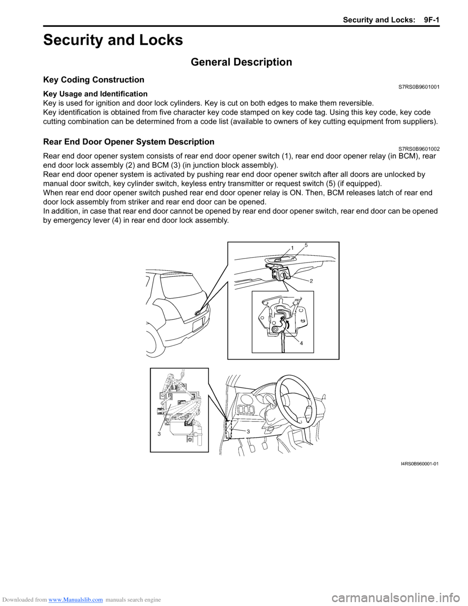
Rear End Door Opener System DescriptionS7RS0B9601002
Rear end door opener system consists of rear end door opener switch (1), rear end door opener relay (in BCM), rear
end door lock assembly (2) and BCM (3) (in junction block assembly).
Rear end door opener system is activated by pushing re ar end door opener switch after all doors are unlocked by
manual door switch, key cylinder s witch, keyless entry transmitter or request switch (5) (if equipped).
When rear end door opener switch pushed rear end door opener relay is ON. Then, BCM releases latch of rear end
door lock assembly from striker and rear end door can be opened.
In addition, in case that rear end door cannot be opened by rear end door opener switch, rear end door can be opened
by emergency lever (4) in rear end door lock assembly.
I4RS0B960001-01
Page 1351 of 1496
Downloaded from www.Manualslib.com manuals search engine Security and Locks: 9F-5
Keyless Entry System Operation InspectionS7RS0B9604004
NOTE
When performing the this inspection, make
sure to have any of the door once opened/
closed after the ignition key has been
removed from the ignition key cylinder.
1) Confirm that power door lock system operates normally, refer to “Power Door Lock System
Operation Inspection”.
2) All doors are closed and unlocked.
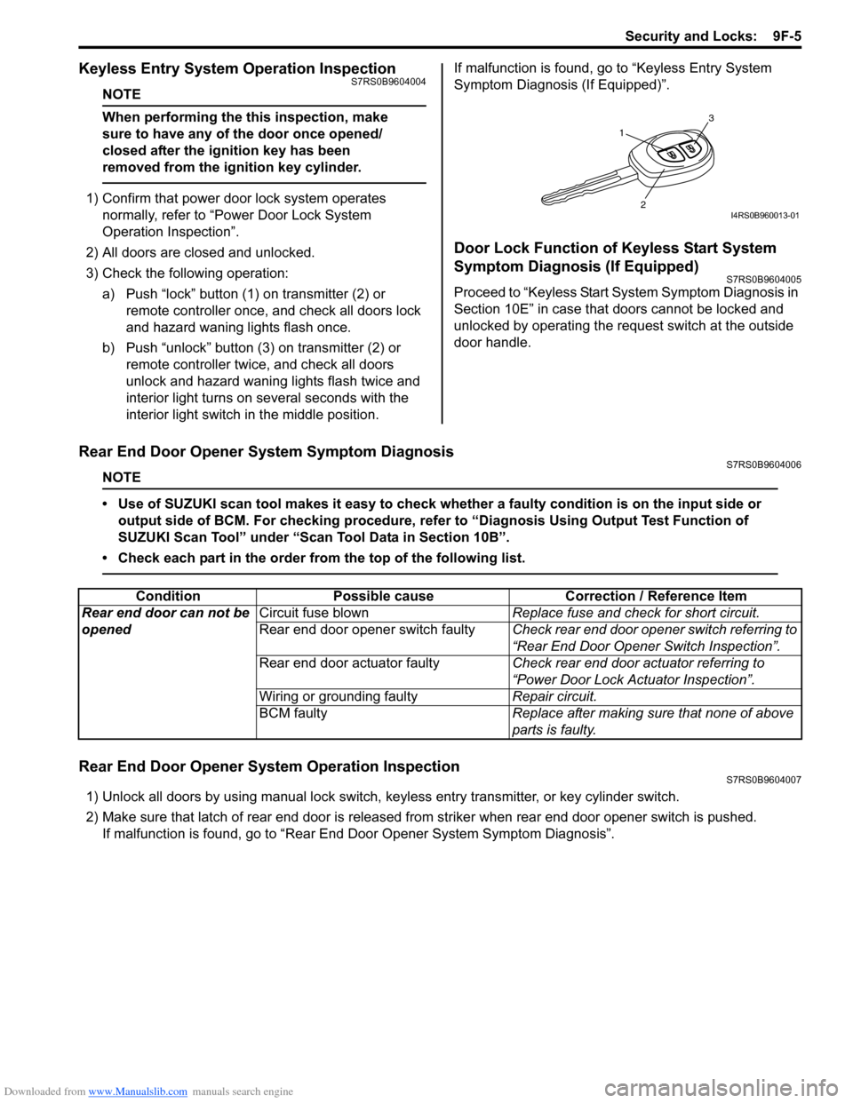
3) Check the following operation: a) Push “lock” button (1 ) on transmitter (2) or
remote controller once, and check all doors lock
and hazard waning lights flash once.
b) Push “unlock” button (3) on transmitter (2) or remote controller twice, and check all doors
unlock and hazard waning lights flash twice and
interior light turns on several seconds with the
interior light switch in the middle position. If malfunction is found, go to “Keyless Entry System
Symptom Diagnosis (If Equipped)”.
Door Lock Function of Keyless Start System
Symptom Diagnosis (If Equipped)
S7RS0B9604005
Proceed to “Keyless Start System Symptom Diagnosis in
Section 10E” in case that doors cannot be locked and
unlocked by operating the request switch at the outside
door handle.
Rear End Door Opener System Symptom DiagnosisS7RS0B9604006
NOTE
• Use of SUZUKI scan tool makes it easy to check wh
ether a faulty condition is on the input side or
output side of BCM. For checking procedure, re fer to “Diagnosis Using Output Test Function of
SUZUKI Scan Tool” under “Scan Tool Data in Section 10B”.
• Check each part in the order from the top of the following list.
Rear End Door Opener System Operation InspectionS7RS0B9604007
1) Unlock all doors by using manu al lock switch, keyless entry transmitter, or key cylinder switch.
2) Make sure that latch of rear end door is released from striker when rear end door opener switch is pushed. If malfunction is found, go to “Rear End Door Opener System Symptom Diagnosis”.
1
3
2I4RS0B960013-01
ConditionPossible cause Correction / Reference Item
Rear end door can not be
opened Circuit fuse blown
Replace fuse and check for short circuit.
Rear end door opener switch faulty Check rear end door opener switch referring to
“Rear End Door Opener Switch Inspection”.
Rear end door actuator faulty Check rear end door actuator referring to
“Power Door Lock Actuator Inspection”.
Wiring or grounding faulty Repair circuit.
BCM faulty Replace after making sure that none of above
parts is faulty.
Page 1357 of 1496
Downloaded from www.Manualslib.com manuals search engine Security and Locks: 9F-11
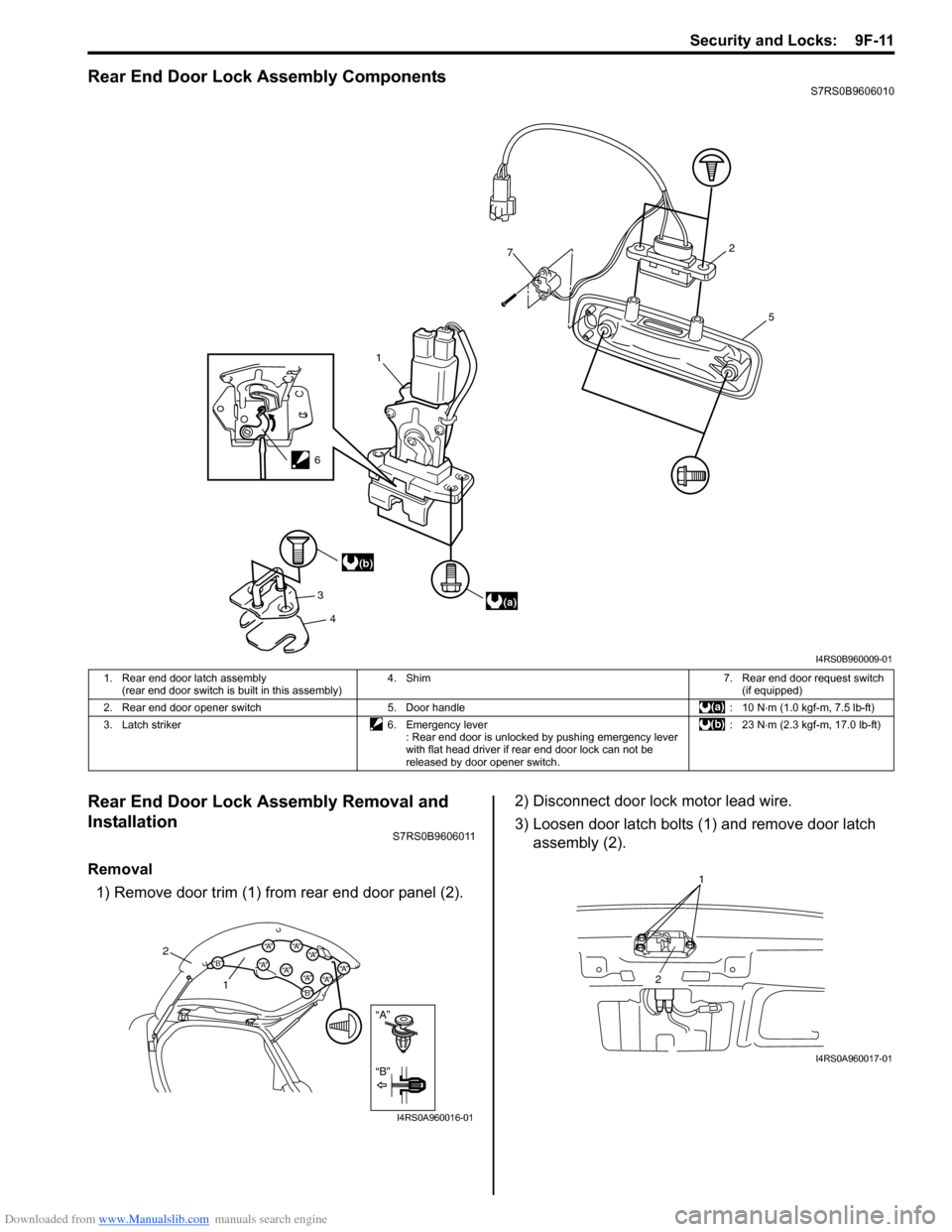
Rear End Door Lock Assembly ComponentsS7RS0B9606010
Rear End Door Lock Assembly Removal and
Installation
S7RS0B9606011
Removal1) Remove door trim (1) from rear end door panel (2). 2) Disconnect door lock motor lead wire.
3) Loosen door latch bolts (1) and remove door latch
assembly (2).
1
7
3 4 5
2
(a)
(b)
6
I4RS0B960009-01
1. Rear end door latch assembly
(rear end door switch is built in this assembly) 4. Shim 7. Rear end door request switch
(if equipped)
2. Rear end door opener switch 5. Door handle : 10 N⋅ m (1.0 kgf-m, 7.5 lb-ft)
3. Latch striker 6. Emergency lever : Rear end door is unlocked by pushing emergency lever
with flat head driver if rear end door lock can not be
released by door opener switch. :23 N
⋅m (2.3 kgf-m, 17.0 lb-ft)
“A”
“B”
“B”
“A”“B”“A”“A”“A”
“A”“A”“A”
“A”
2
1
I4RS0A960016-01
1
2
I4RS0A960017-01