brake pedal SUZUKI SWIFT 2008 2.G Service User Guide
[x] Cancel search | Manufacturer: SUZUKI, Model Year: 2008, Model line: SWIFT, Model: SUZUKI SWIFT 2008 2.GPages: 1496, PDF Size: 34.44 MB
Page 147 of 1496
Downloaded from www.Manualslib.com manuals search engine Engine General Information and Diagnosis: 1A-97
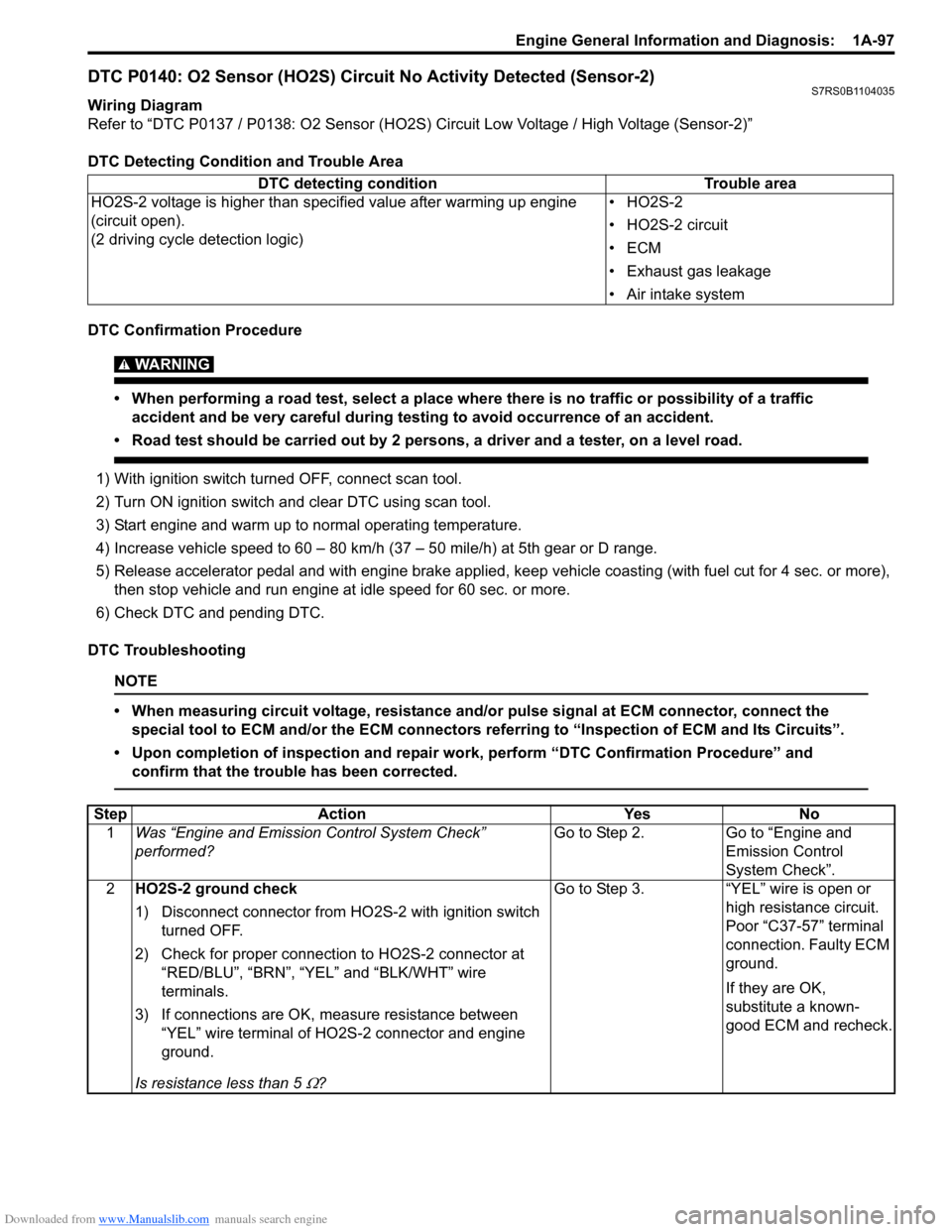
DTC P0140: O2 Sensor (HO2S) Circuit No Activity Detected (Sensor-2)S7RS0B1104035
Wiring Diagram
Refer to “DTC P0137 / P0138: O2 Sensor (HO2S) Circuit Low Voltage / High Voltage (Sensor-2)”
DTC Detecting Condition and Trouble Area
DTC Confirmation Procedure
WARNING!
• When performing a road test, select a place where there is no traffic or possibility of a traffic accident and be very careful during testing to avoid occurrence of an accident.
• Road test should be carried out by 2 persons, a driver and a tester, on a level road.
1) With ignition switch turned OFF, connect scan tool.
2) Turn ON ignition switch and clear DTC using scan tool.
3) Start engine and warm up to normal operating temperature.
4) Increase vehicle speed to 60 – 80 km/h (37 – 50 mile/h) at 5th gear or D range.
5) Release accelerator pedal and with engine brake applied, ke ep vehicle coasting (with fuel cut for 4 sec. or more),
then stop vehicle and run engine at idle speed for 60 sec. or more.
6) Check DTC and pending DTC.
DTC Troubleshooting
NOTE
• When measuring circuit voltage, resistance and/ or pulse signal at ECM connector, connect the
special tool to ECM and/or the ECM connectors re ferring to “Inspection of ECM and Its Circuits”.
• Upon completion of inspection and repair work, perform “DTC Confirmation Procedure” and confirm that the trouble has been corrected.
DTC detecting condition Trouble area
HO2S-2 voltage is higher than specified value after warming up engine
(circuit open).
(2 driving cycle detection logic) •HO2S-2
• HO2S-2 circuit
•ECM
• Exhaust gas leakage
• Air intake system
Step
Action YesNo
1 Was “Engine and Emission Control System Check”
performed? Go to Step 2.
Go to “Engine and
Emission Control
System Check”.
2 HO2S-2 ground check
1) Disconnect connector from HO 2S-2 with ignition switch
turned OFF.
2) Check for proper connection to HO2S-2 connector at “RED/BLU”, “BRN”, “YEL” and “BLK/WHT” wire
terminals.
3) If connections are OK, m easure resistance between
“YEL” wire terminal of HO2S-2 connector and engine
ground.
Is resistance less than 5
Ω? Go to Step 3. “YEL” wire is open or
high resistance circuit.
Poor “C37-57” terminal
connection. Faulty ECM
ground.
If they are OK,
substitute a known-
good ECM and recheck.
Page 167 of 1496
Downloaded from www.Manualslib.com manuals search engine Engine General Information and Diagnosis: 1A-117
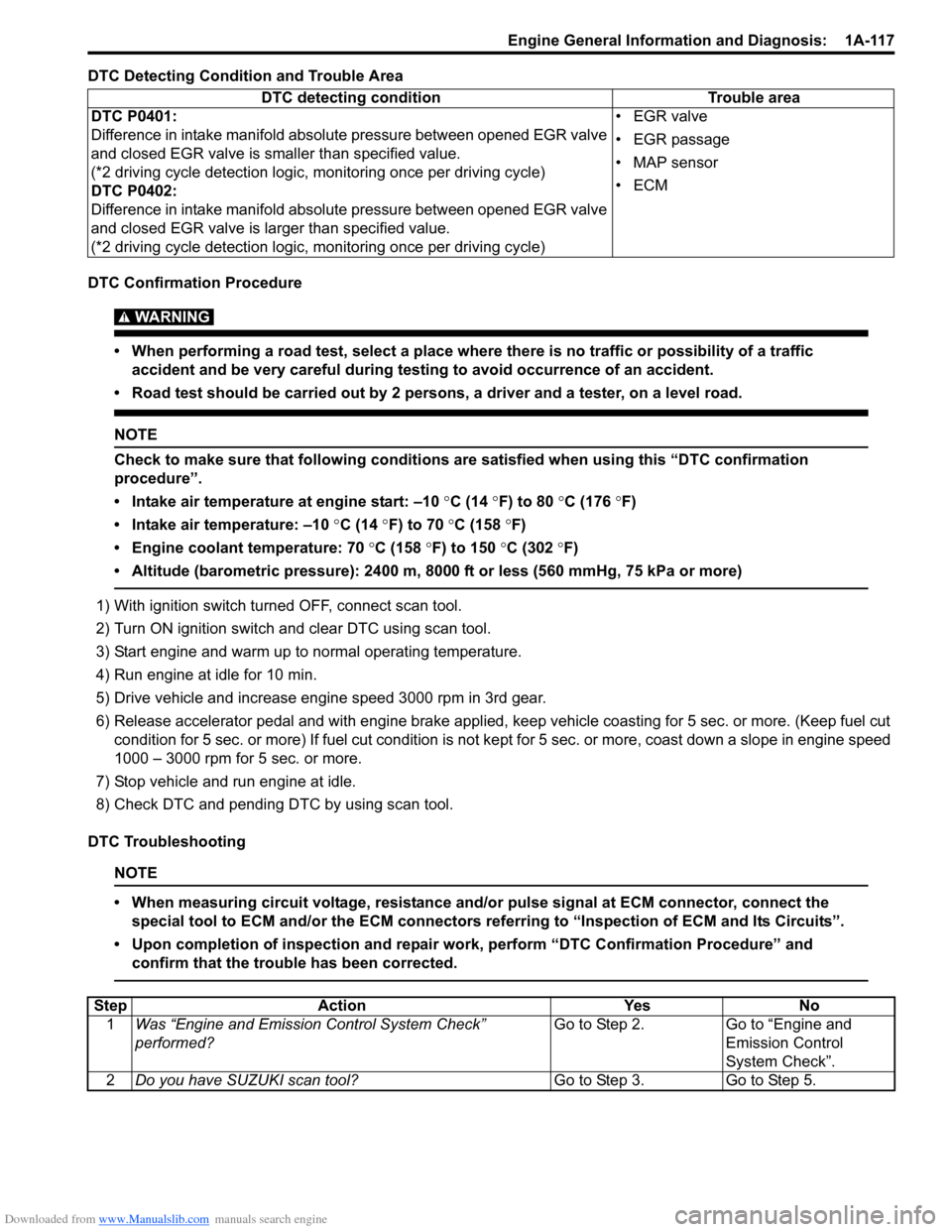
DTC Detecting Condition and Trouble Area
DTC Confirmation Procedure
WARNING!
• When performing a road test, select a place where there is no traffic or possibility of a traffic accident and be very careful during testing to avoid occurrence of an accident.
• Road test should be carried out by 2 persons, a driver and a tester, on a level road.
NOTE
Check to make sure that following conditions ar e satisfied when using this “DTC confirmation
procedure”.
• Intake air temperature at engine start: –10 °C (14 ° F) to 80 °C (176 °F)
• Intake air temperature: –10 °C (14 °F) to 70 °C (158 °F)
• Engine coolant temperature: 70 °C (158 °F) to 150 °C (302 °F)
• Altitude (barometric pressure): 2400 m, 8000 ft or less (560 mmHg, 75 kPa or more)
1) With ignition switch turned OFF, connect scan tool.
2) Turn ON ignition switch and clear DTC using scan tool.
3) Start engine and warm up to normal operating temperature.
4) Run engine at idle for 10 min.
5) Drive vehicle and increase engine speed 3000 rpm in 3rd gear.
6) Release accelerator pedal and with engine brake applied, keep vehicle coasting for 5 sec. or more. (Keep fuel cut condition for 5 sec. or more) If fuel cut condition is not ke pt for 5 sec. or more, coast down a slope in engine speed
1000 – 3000 rpm for 5 sec. or more.
7) Stop vehicle and run engine at idle.
8) Check DTC and pending DTC by using scan tool.
DTC Troubleshooting
NOTE
• When measuring circuit voltage, resistance and/ or pulse signal at ECM connector, connect the
special tool to ECM and/or the ECM connectors re ferring to “Inspection of ECM and Its Circuits”.
• Upon completion of inspection and repair work, perform “DTC Confirmation Procedure” and confirm that the trouble has been corrected.
DTC detecting condition Trouble area
DTC P0401:
Difference in intake manifold absolute pressure between opened EGR valve
and closed EGR valve is smaller than specified value.
(*2 driving cycle detection logic, monitoring once per driving cycle)
DTC P0402:
Difference in intake manifold absolute pressure between opened EGR valve
and closed EGR valve is la rger than specified value.
(*2 driving cycle detection logic, monitoring once per driving cycle) •EGR valve
• EGR passage
• MAP sensor
•ECM
Step
Action YesNo
1 Was “Engine and Emission Control System Check”
performed? Go to Step 2.
Go to “Engine and
Emission Control
System Check”.
2 Do you have SUZUKI scan tool? Go to Step 3.Go to Step 5.
Page 179 of 1496
Downloaded from www.Manualslib.com manuals search engine Engine General Information and Diagnosis: 1A-129
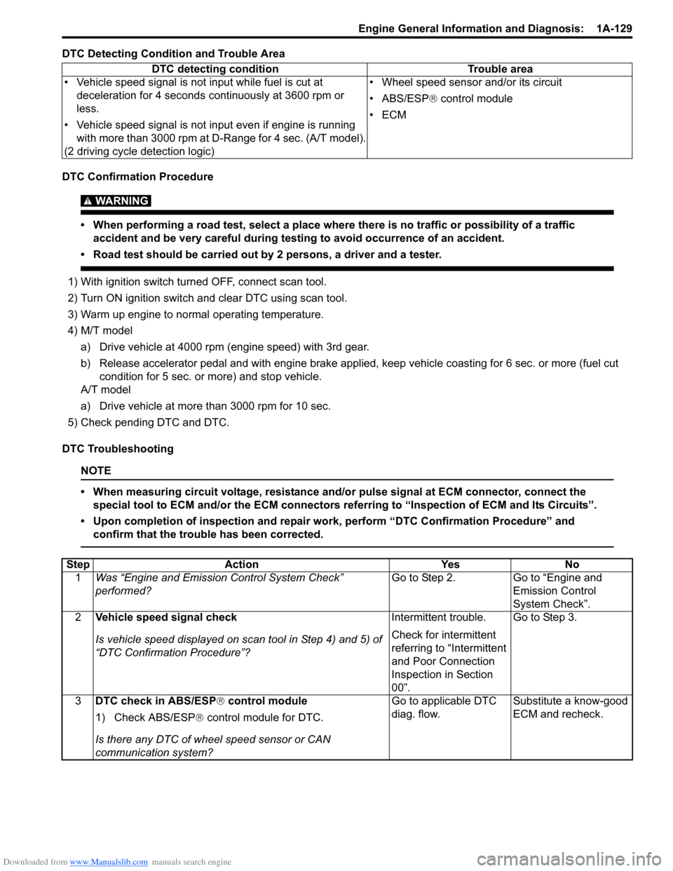
DTC Detecting Condition and Trouble Area
DTC Confirmation Procedure
WARNING!
• When performing a road test, select a place where there is no traffic or possibility of a traffic accident and be very careful during testing to avoid occurrence of an accident.
• Road test should be carried out by 2 persons, a driver and a tester.
1) With ignition switch turned OFF, connect scan tool.
2) Turn ON ignition switch and clear DTC using scan tool.
3) Warm up engine to normal operating temperature.
4) M/T model
a) Drive vehicle at 4000 rpm (e ngine speed) with 3rd gear.
b) Release accelerator pedal and with engine brake applied, keep vehicle coasting for 6 sec. or more (fuel cut condition for 5 sec. or more) and stop vehicle.
A/T model
a) Drive vehicle at more than 3000 rpm for 10 sec.
5) Check pending DTC and DTC.
DTC Troubleshooting
NOTE
• When measuring circuit voltage, resistance and/ or pulse signal at ECM connector, connect the
special tool to ECM and/or the ECM connectors re ferring to “Inspection of ECM and Its Circuits”.
• Upon completion of inspection and repair work, perform “DTC Confirmation Procedure” and confirm that the trouble has been corrected.
DTC detecting condition Trouble area
• Vehicle speed signal is not input while fuel is cut at deceleration for 4 seconds continuously at 3600 rpm or
less.
• Vehicle speed signal is not input even if engine is running with more than 3000 rpm at D-Range for 4 sec. (A/T model).
(2 driving cycle detection logic) • Wheel speed sensor and/or its circuit
• ABS/ESP®
control module
•ECM
Step Action YesNo
1 Was “Engine and Emission Control System Check”
performed? Go to Step 2.
Go to “Engine and
Emission Control
System Check”.
2 Vehicle speed signal check
Is vehicle speed displayed on scan tool in Step 4) and 5) of
“DTC Confirmation Procedure”? Intermittent trouble.
Check for intermittent
referring to “Intermittent
and Poor Connection
Inspection in Section
00”.Go to Step 3.
3 DTC check in ABS/ESP ® control module
1) Check ABS/ESP ® control module for DTC.
Is there any DTC of wheel speed sensor or CAN
communication system? Go to applicable DTC
diag. flow.
Substitute a know-good
ECM and recheck.
Page 268 of 1496
Downloaded from www.Manualslib.com manuals search engine 1B-1 Aux. Emission Control Devices:
Engine
Aux. Emission Control Devices
Diagnostic Information and Procedures
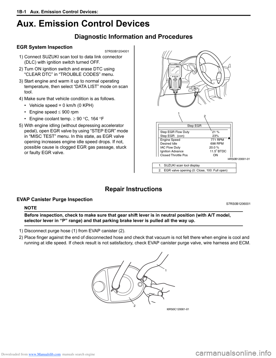
EGR System InspectionS7RS0B1204001
1) Connect SUZUKI scan tool to data link connector (DLC) with ignition switch turned OFF.
2) Turn ON ignition switch and erase DTC using “CLEAR DTC” in “TROUBLE CODES” menu.
3) Start engine and warm it up to normal operating temperature, then select “DATA LIST” mode on scan
tool.
4) Make sure that vehicle condition is as follows.
• Vehicle speed = 0 km/h (0 KPH)
• Engine speed ≤ 900 rpm
• Engine coolant temp. ≥ 90 °C, 164 °F
5) With engine idling (without depressing accelerator pedal), open EGR valve by using “STEP EGR” mode
in “MISC TEST” menu. In this state, as EGR valve
opening increases engine idle speed drops. If not,
possible cause is clogged EGR gas passage, stuck
or faulty EGR valve.
Repair Instructions
EVAP Canister Purge InspectionS7RS0B1206001
NOTE
Before inspection, check to make sure that gear shift lever is in neutral position (with A/T model,
selector lever in “P” range) and that parking brake lever is pulled all the way up.
1) Disconnect purge hose (1) from EVAP canister (2).
2) Place finger against the end of disconne cted hose and check that vacuum is not felt there when engine is cool and
running at idle speed. If check result is not satisfacto ry, check EVAP canister purge valve, wire harness and ECM.
1. SUZUKI scan tool display
2. EGR valve opening (0: Close, 100: Full open)
Step EGR
Step EGR Flow Duty 21 %
Step EGR (con) 23%
Engine Speed 771 RPM
Desired Idle 698 RPM
IAC Flow Duty 20.0 %
Ignition Advance 11.5 BTDC
Closed Throttle Pos ON
1 2
I4RS0B120001-01
1
2
I6RS0C120001-01
Page 290 of 1496
Downloaded from www.Manualslib.com manuals search engine 1D-5 Engine Mechanical:
11) Connect negative cable at battery.
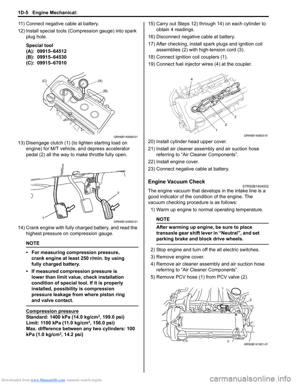
12) Install special tools (Compression gauge) into spark plug hole.
Special tool
(A): 09915–64512
(B): 09915–64530
(C): 09915–67010
13) Disengage clutch (1) (to lighten starting load on engine) for M/T vehicle, and depress accelerator
pedal (2) all the way to make throttle fully open.
14) Crank engine with fully charged battery, and read the highest pressure on compression gauge.
NOTE
• For measuring compression pressure, crank engine at least 250 r/min. by using
fully charged battery.
• If measured compression pressure is lower than limit value, check installation
condition of special tool. If it is properly
installed, possibility is compression
pressure leakage from where piston ring
and valve contact.
Compression pressure
Standard: 1400 kPa (14.0 kg/cm2, 199.0 psi)
Limit: 1100 kPa (11.0 kg/cm2, 156.0 psi)
Max. difference between any two cylinders: 100
kPa (1.0 kg/cm
2, 14.2 psi) 15) Carry out Steps 12) through 14) on each cylinder to
obtain 4 readings.
16) Disconnect negative cable at battery.
17) After checking, install spark plugs and ignition coil assemblies (2) with high-tension cord (3).
18) Connect ignition coil couplers (1).
19) Connect fuel injector wires (4) at the coupler.
20) Install cylinder head upper cover.
21) Install air cleaner assembly and air suction hose referring to “Air Cleaner Components”.
22) Install engine cover.
23) Connect negative cable at battery.
Engine Vacuum CheckS7RS0B1404002
The engine vacuum that develops in the intake line is a
good indicator of the condition of the engine. The
vacuum checking procedure is as follows:
1) Warm up engine to normal operating temperature.
NOTE
After warming up engine, be sure to place
transaxle gear shift lever in “Neutral”, and set
parking brake and block drive wheels.
2) Stop engine and turn off the all electric switches.
3) Remove engine cover.
4) Remove air cleaner assembly and air suction hose referring to “Air Cleaner Components”.
5) Remove PCV hose (1) from PCV valve (2).
(A)
(C)
(B)
I3RH0B140009-01
I2RH0B140005-01
I2RH0B140003-01
2
1
I6RS0B141001-01
Page 441 of 1496
Downloaded from www.Manualslib.com manuals search engine Front Suspension: 2B-8
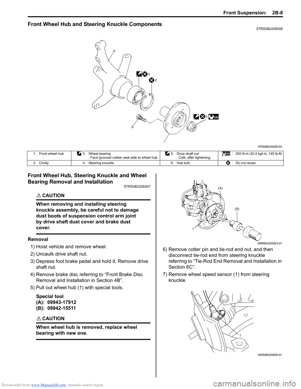
Front Wheel Hub and Steering Knuckle ComponentsS7RS0B2206006
Front Wheel Hub, Steering Knuckle and Wheel
Bearing Removal and Installation
S7RS0B2206007
CAUTION!
When removing and installing steering
knuckle assembly, be careful not to damage
dust boots of suspension control arm joint
by drive shaft dust cover and brake dust
cover.
Removal1) Hoist vehicle and remove wheel.
2) Uncaulk drive shaft nut.
3) Depress foot brake pedal and hold it. Remove drive shaft nut.
4) Remove brake disc referring to “Front Brake Disc Removal and Installa tion in Section 4B”.
5) Pull out wheel hub (1) with special tools.
Special tool
(A): 09943-17912
(B): 09942-15511
CAUTION!
When wheel hub is removed, replace wheel
bearing with new one.
6) Remove cotter pin and tie-rod end nut, and then disconnect tie-rod end from steering knuckle
referring to “Tie-Rod End Removal and Installation in
Section 6C”.
7) Remove wheel speed sensor (1) from steering knuckle.
I7RS0B220005-03
1. Front wheel hub 3. Wheel bearing
: Face grooved rubber seal side to wheel hub. 5. Drive shaft nut
: Calk, after tightening. : 200 N
⋅m (20.0 kgf-m, 145 lb-ft)
2. Circlip 4. Steering knuckle 6. Hub bolt: Do not reuse.
I3RM0A220023-01
1
I4RS0B220005-01
Page 444 of 1496
Downloaded from www.Manualslib.com manuals search engine 2B-11 Front Suspension:
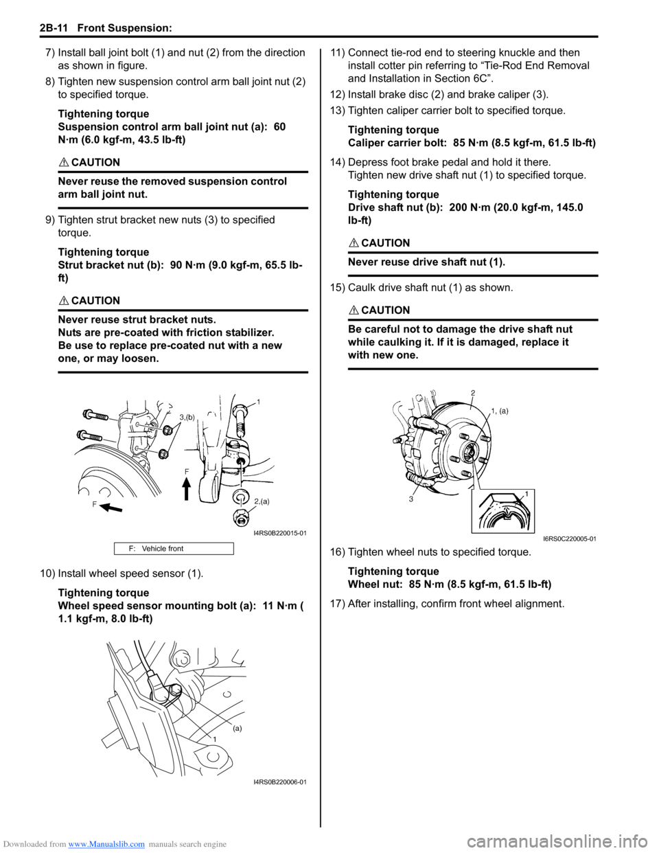
7) Install ball joint bolt (1) and nut (2) from the direction
as shown in figure.
8) Tighten new suspension co ntrol arm ball joint nut (2)
to specified torque.
Tightening torque
Suspension control arm ball joint nut (a): 60
N·m (6.0 kgf-m, 43.5 lb-ft)
CAUTION!
Never reuse the removed suspension control
arm ball joint nut.
9) Tighten strut bracket new nuts (3) to specified torque.
Tightening torque
Strut bracket nut (b): 90 N·m (9.0 kgf-m, 65.5 lb-
ft)
CAUTION!
Never reuse strut bracket nuts.
Nuts are pre-coated with friction stabilizer.
Be use to replace pre-coated nut with a new
one, or may loosen.
10) Install wheel speed sensor (1).
Tightening torque
Wheel speed sensor mounting bolt (a): 11 N·m (
1.1 kgf-m, 8.0 lb-ft) 11) Connect tie-rod end to steering knuckle and then
install cotter pin referrin g to “Tie-Rod End Removal
and Installation in Section 6C”.
12) Install brake disc (2) and brake caliper (3).
13) Tighten caliper carrier bolt to specified torque.
Tightening torque
Caliper carrier bolt: 85 N·m (8.5 kgf-m, 61.5 lb-ft)
14) Depress foot brake pedal and hold it there. Tighten new drive shaft nut (1) to specified torque.
Tightening torque
Drive shaft nut (b): 200 N·m (20.0 kgf-m, 145.0
lb-ft)
CAUTION!
Never reuse drive shaft nut (1).
15) Caulk drive shaft nut (1) as shown.
CAUTION!
Be careful not to damage the drive shaft nut
while caulking it. If it is damaged, replace it
with new one.
16) Tighten wheel nuts to specified torque.
Tightening torque
Wheel nut: 85 N·m (8.5 kgf-m, 61.5 lb-ft)
17) After installing, confirm front wheel alignment.F: Vehicle front
I4RS0B220015-01
1 (a)
I4RS0B220006-01
I6RS0C220005-01
Page 495 of 1496
Downloaded from www.Manualslib.com manuals search engine Table of Contents 4- i
4
Section 4
CONTENTS
Brakes
Precautions ................................................. 4-1
Precautions............................................................. 4-1
Precautions for Brakes .......................................... 4-1
Brake Control System and Diagnosis ... 4A-1
Precautions........................................................... 4A-1Precautions on Brake .......................................... 4A-1
General Description ............................................. 4A-1 Brakes Construction ............................................ 4A-1
Brake Pedal Foot Protection System Construction ...................................................... 4A-2
Front Brake Hose / Pipe Co nstruction................. 4A-3
Rear Brake Hose / Pipe Construction ................. 4A-4
Diagnostic Information and Procedures ............ 4A-4 Brakes Diagnosis Note ....................................... 4A-4
Brakes Symptom Diagnosis ................................ 4A-5
Repair Instructions .............................................. 4A-7 Brake Pedal Components ................................... 4A-7
Brake Pedal Free Height Inspection ................... 4A-7
Brake Pedal Play Inspection ............................... 4A-7
Excessive Pedal Travel Inspection ..................... 4A-8
Brake Fluid Level Inspection ............................... 4A-8
Stop Light Switch Adjustment ............................. 4A-8
Air Bleeding of Brake System ............................. 4A-9
Front Brake Hose / Pipe Removal and Installation ....................................................... 4A-10
Rear Brake Hose / Pipe Removal and Installation ....................................................... 4A-10
Brake Hose and Pipe Inspection ....................... 4A-11
Master Cylinder Components............................ 4A-11
Master Cylinder Assembly Removal and Installation ....................................................... 4A-12
Master Cylinder Rese rvoir Removal and
Installation ....................................................... 4A-13
Master Cylinder Assemb ly Disassembly and
Assembly ........................................................ 4A-14
Master Cylinder Assembly Inspection ............... 4A-15
Brake Booster Components .............................. 4A-15
Booster Operation Inspection ........................... 4A-16
Brake Booster Removal and Installation ........... 4A-17
Brake Booster Inspection and Adjustment ........ 4A-18
Specifications ..................................................... 4A-18
Tightening Torque Specifications ...................... 4A-18
Special Tools and Equipmen t ........................... 4A-18 Recommended Service Material ....................... 4A-18
Front Brakes .......
..................................... 4B-1
Repair Instructions ........... ...................................4B-1
Front Disc Brake Components ............................ 4B-1
Front Disc Brake Pad On-Vehicle Inspection ...... 4B-2
Front Disc Brake Pad Removal and Installation ......................................................... 4B-2
Front Disc Brake Pad Inspection......................... 4B-3
Front Disc Brake Ca liper Removal and
Installation ......................................................... 4B-3
Front Disc Brake Caliper Disassembly and Assembly........................................................... 4B-4
Front Disc Brake Caliper In spection.................... 4B-6
Front Brake Disc Removal and Installation ......... 4B-6
Front Brake Disc Inspection ................................ 4B-7
Specifications .................... ...................................4B-8
Tightening Torque Specifications ........................ 4B-8
Special Tools and Equipmen t .............................4B-8
Recommended Service Material ......................... 4B-8
Special Tool ........................................................ 4B-8
Rear Brakes................... ........................... 4C-1
Repair Instructions ........... ...................................4C-1
Rear Disc Brake Components.............................4C-1
Rear Disc Brake Pad Removal and Installation .........................................................4C-2
Rear Disc Brake Caliper Removal and Installation .........................................................4C-3
Rear Disc Brake Pad Inspection .........................4C-6
Rear Disc Brake Caliper Disassembly and Assembly...........................................................4C-6
Rear Disc Brake Caliper Inspection ....................4C-8
Rear Flexible Hose Remova l and Installation .....4C-8
Rear Brake Disc Removal and Installation..........4C-9
Rear Brake Disc Inspection.................................4C-9
Specifications .................... .................................4C-10
Tightening Torque Specifications ......................4C-10
Special Tools and Equipmen t ...........................4C-11
Recommended Service Material .......................4C-11
Special Tool ......................................................4C-11
Parking Brake ................. ......................... 4D-1
General Description .............................................4D-1
Parking Brake Cable Construction ......................4D-1
Page 499 of 1496
Downloaded from www.Manualslib.com manuals search engine Brake Control System and Diagnosis: 4A-1
Brakes
Brake Control System and Diagnosis
Precautions
Precautions on BrakeS7RS0B4100001
Air Bag Warning
Refer to “Air Bag System Service Warning in Section 00”.
Brakes Diagnosis Note
Refer to “Brakes Diagnosis Note”.
General Description
Brakes ConstructionS7RS0B4101001
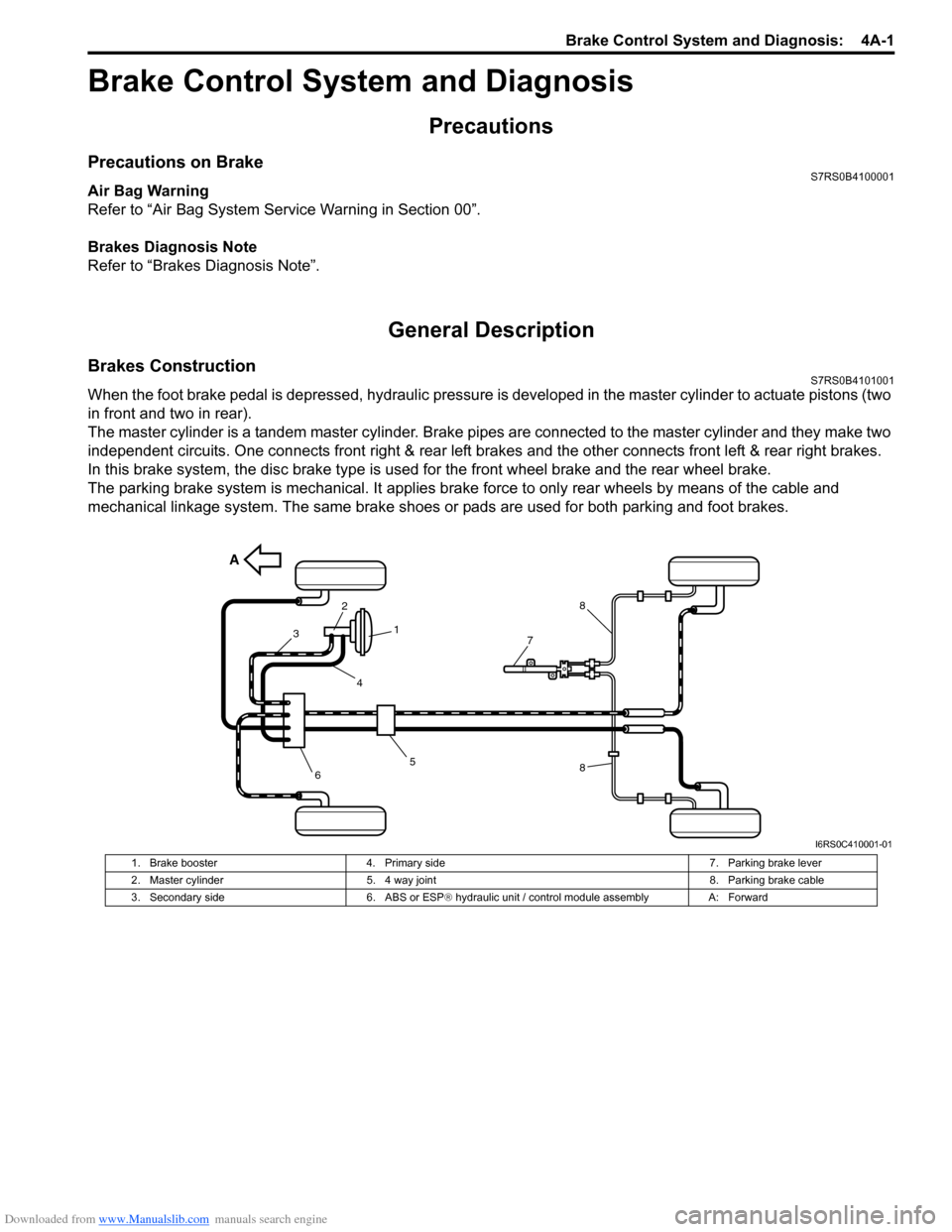
When the foot brake pedal is depressed, hydraulic pressure is developed in the master cylinder to actuate pistons (two
in front and two in rear).
The master cylinder is a tandem master cylinder. Brake pipes are connected to the master cylinder and they make two
independent circuits. One connects front right & rear left brakes and the other connects front left & rear right brakes.
In this brake system, the disc brake type is used for the front wheel brake and the rear wheel brake.
The parking brake system is mechanical. It applies brake force to only rear wheels by means of the cable and
mechanical linkage system. The same brake shoes or pads are used for both parking and foot brakes.
A
5
3
2
1
4
8
8
6
7
I6RS0C410001-01
1. Brake booster 4. Primary side 7. Parking brake lever
2. Master cylinder 5. 4 way joint 8. Parking brake cable
3. Secondary side 6. ABS or ESP® hydraulic unit / control module assembly A: Forward
Page 500 of 1496
Downloaded from www.Manualslib.com manuals search engine 4A-2 Brake Control System and Diagnosis:
Brake Pedal Foot Protection System ConstructionS7RS0B4101004
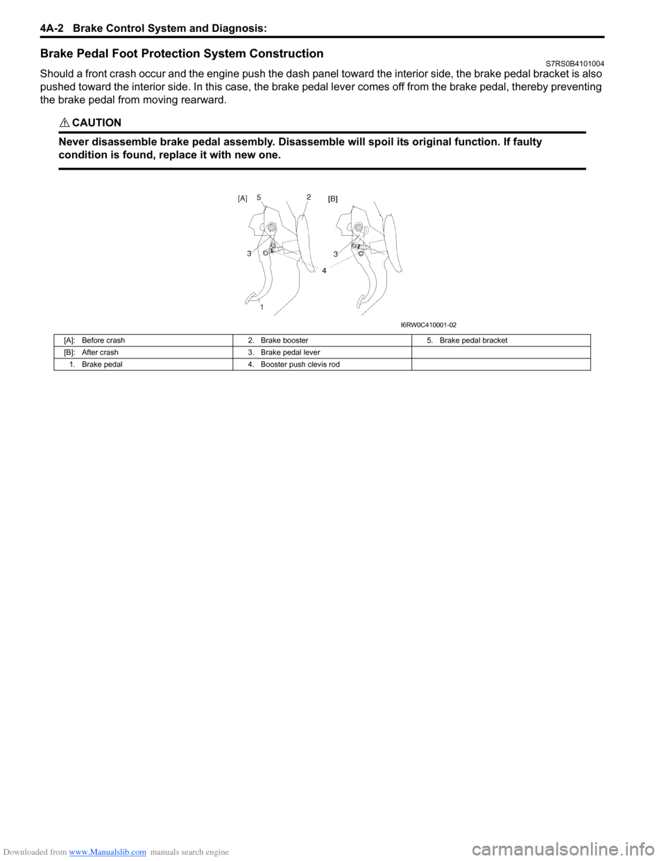
Should a front crash occur and the engine push the dash panel toward the interior side, the brake pedal bracket is also
pushed toward the interior side. In this case, the brake pedal lever comes off from the brake pedal, thereby preventing
the brake pedal from moving rearward.
CAUTION!
Never disassemble brake pedal assembly. Disassemble will spoil its original function. If faulty
condition is found, replace it with new one.
[A]: Before crash2. Brake booster5. Brake pedal bracket
[B]: After crash 3. Brake pedal lever
1. Brake pedal 4. Booster push clevis rod
I6RW0C410001-02