wheels SUZUKI SWIFT 2008 2.G Service User Guide
[x] Cancel search | Manufacturer: SUZUKI, Model Year: 2008, Model line: SWIFT, Model: SUZUKI SWIFT 2008 2.GPages: 1496, PDF Size: 34.44 MB
Page 290 of 1496
Downloaded from www.Manualslib.com manuals search engine 1D-5 Engine Mechanical:
11) Connect negative cable at battery.
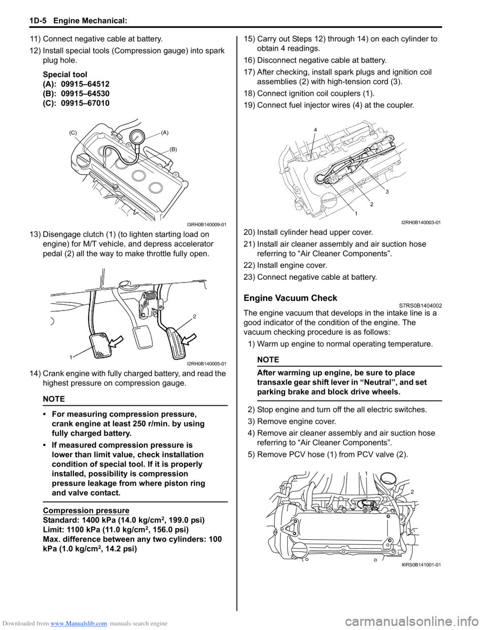
12) Install special tools (Compression gauge) into spark plug hole.
Special tool
(A): 09915–64512
(B): 09915–64530
(C): 09915–67010
13) Disengage clutch (1) (to lighten starting load on engine) for M/T vehicle, and depress accelerator
pedal (2) all the way to make throttle fully open.
14) Crank engine with fully charged battery, and read the highest pressure on compression gauge.
NOTE
• For measuring compression pressure, crank engine at least 250 r/min. by using
fully charged battery.
• If measured compression pressure is lower than limit value, check installation
condition of special tool. If it is properly
installed, possibility is compression
pressure leakage from where piston ring
and valve contact.
Compression pressure
Standard: 1400 kPa (14.0 kg/cm2, 199.0 psi)
Limit: 1100 kPa (11.0 kg/cm2, 156.0 psi)
Max. difference between any two cylinders: 100
kPa (1.0 kg/cm
2, 14.2 psi) 15) Carry out Steps 12) through 14) on each cylinder to
obtain 4 readings.
16) Disconnect negative cable at battery.
17) After checking, install spark plugs and ignition coil assemblies (2) with high-tension cord (3).
18) Connect ignition coil couplers (1).
19) Connect fuel injector wires (4) at the coupler.
20) Install cylinder head upper cover.
21) Install air cleaner assembly and air suction hose referring to “Air Cleaner Components”.
22) Install engine cover.
23) Connect negative cable at battery.
Engine Vacuum CheckS7RS0B1404002
The engine vacuum that develops in the intake line is a
good indicator of the condition of the engine. The
vacuum checking procedure is as follows:
1) Warm up engine to normal operating temperature.
NOTE
After warming up engine, be sure to place
transaxle gear shift lever in “Neutral”, and set
parking brake and block drive wheels.
2) Stop engine and turn off the all electric switches.
3) Remove engine cover.
4) Remove air cleaner assembly and air suction hose referring to “Air Cleaner Components”.
5) Remove PCV hose (1) from PCV valve (2).
(A)
(C)
(B)
I3RH0B140009-01
I2RH0B140005-01
I2RH0B140003-01
2
1
I6RS0B141001-01
Page 355 of 1496
Downloaded from www.Manualslib.com manuals search engine Engine Lubrication System: 1E-3
6) Start engine and warm engine up to normal operating temperature.
NOTE
Be sure to shift transaxle gear shift lever in
“Neutral” (shift select lever in “P” range for
A/T vehicle), set parking brake and block
drive wheels.
7) After warming up, raise engine speed to 4,000 r/min. and measure oil pressure.
Oil pressure specification
More than 270 kPa (2.7 kg/cm2, 39.8 psi) at 4,000
r/min. (rpm)
8) After checking oil pressure, stop engine and remove oil pressure gauge and attachment.
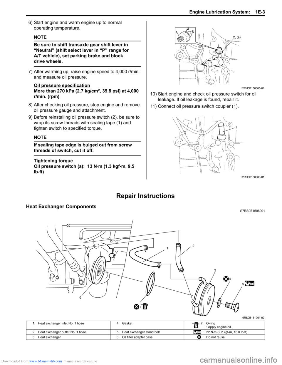
9) Before reinstalling oil pressure switch (2), be sure to
wrap its screw threads with sealing tape (1) and
tighten switch to specified torque.
NOTE
If sealing tape edge is bulged out from screw
threads of switch, cut it off.
Tightening torque
Oil pressure switch (a): 13 N·m (1.3 kgf-m, 9.5
lb-ft) 10) Start engine and check oil pressure switch for oil
leakage. If oil leakage is found, repair it.
11) Connect oil pressure switch coupler (1).
Repair Instructions
Heat Exchanger ComponentsS7RS0B1506001
I2RH0B150005-01
I2RH0B150006-01
3
4
5
7
6
(a)
2
1
I6RS0B151001-02
1. Heat exchanger inlet No. 1 hose 4. Gasket7. O-ring
: Apply engine oil.
2. Heat exchanger outlet No. 1 hose 5. Heat exchanger stand bolt : 22 N⋅m (2.2 kgf-m, 16.0 lb-ft)
3. Heat exchanger 6. Oil filter adapter case : Do not reuse.
Page 382 of 1496
Downloaded from www.Manualslib.com manuals search engine 1G-7 Fuel System:
Fuel Pressure Relief ProcedureS7RS0B1706003
CAUTION!
This work must not be done when engine is
hot. If done so, it may cause adverse effect to
catalyst.
NOTE
If ECM detects DTC(s) after servicing, clear
DTC(s) referring to “DTC Clearance in
Section 1A”.
1) Make sure that engine is cold.
2) Shift transaxle gear shift lever in “Neutral” (shift select lever in “P” range for A/T model), set parking
brake and block drive wheels.
3) Remove relay / fuse box cover.
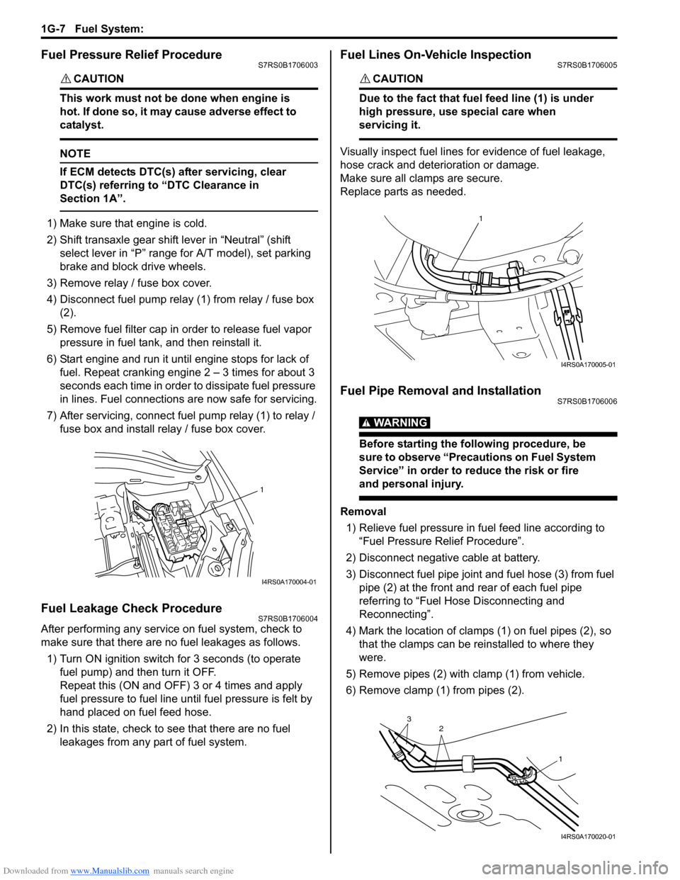
4) Disconnect fuel pump relay (1) from relay / fuse box (2).
5) Remove fuel filter cap in order to release fuel vapor pressure in fuel tank, and then reinstall it.
6) Start engine and run it until engine stops for lack of fuel. Repeat cranking engine 2 – 3 times for about 3
seconds each time in order to dissipate fuel pressure
in lines. Fuel connections are now safe for servicing.
7) After servicing, connect fuel pump relay (1) to relay / fuse box and install re lay / fuse box cover.
Fuel Leakage Check ProcedureS7RS0B1706004
After performing any service on fuel system, check to
make sure that there are no fuel leakages as follows.
1) Turn ON ignition switch for 3 seconds (to operate fuel pump) and then turn it OFF.
Repeat this (ON and OFF) 3 or 4 times and apply
fuel pressure to fuel line until fuel pressure is felt by
hand placed on fuel feed hose.
2) In this state, check to see that there are no fuel leakages from any part of fuel system.
Fuel Lines On-Vehicle InspectionS7RS0B1706005
CAUTION!
Due to the fact that fuel feed line (1) is under
high pressure, use special care when
servicing it.
Visually inspect fuel lines for evidence of fuel leakage,
hose crack and deterioration or damage.
Make sure all cl amps are secure.
Replace parts as needed.
Fuel Pipe Removal and InstallationS7RS0B1706006
WARNING!
Before starting the following procedure, be
sure to observe “Precautions on Fuel System
Service” in order to reduce the risk or fire
and personal injury.
Removal
1) Relieve fuel pressure in fuel feed line according to “Fuel Pressure Relief Procedure”.
2) Disconnect negative cable at battery.
3) Disconnect fuel pipe joint and fuel hose (3) from fuel pipe (2) at the front and rear of each fuel pipe
referring to “Fuel Hose Disconnecting and
Reconnecting”.
4) Mark the location of clamps (1) on fuel pipes (2), so that the clamps can be reinstalled to where they
were.
5) Remove pipes (2) with clamp (1) from vehicle.
6) Remove clamp (1) from pipes (2).
1
I4RS0A170004-01
1
I4RS0A170005-01
2
13
I4RS0A170020-01
Page 429 of 1496
Downloaded from www.Manualslib.com manuals search engine Table of Contents 2- i
2
Section 2
CONTENTS
Suspension
Precautions ................................................. 2-1
Precautions............................................................. 2-1
Precautions on Suspension .................................. 2-1
Suspension General Dia gnosis.............. 2A-1
Diagnostic Information and Procedures ............ 2A-1
Suspension, Wheels and Tires Symptom Diagnosis .......................................................... 2A-1
Front Suspension ........... ......................... 2B-1
General Description ............................................. 2B-1
Front Suspension Construction ........................... 2B-1
Front Wheel Alignment Cons truction .................. 2B-2
Repair Instructions .............................................. 2B-2 Front Wheel Alignment Inspection and Adjustment ........................................................ 2B-2
Front Strut Assembly Comp onents ..................... 2B-4
Front Strut Assembly Removal and Installation ......................................................... 2B-4
Front Strut Assembly Disassembly and Assembly .......................................................... 2B-6
Front Strut Assembly Chec k ............................... 2B-7
Front Wheel Hub and Steering Knuckle Components...................................................... 2B-8
Front Wheel Hub, Steering Knuckle and Wheel Bearing Removal and Installation .......... 2B-8
Front Wheel Hub, Disc, Nut and Bearing Check .............................................................. 2B-12
Suspension Control Arm / Bushing Removal and Installation ................................................ 2B-12
Suspension Control Arm / Bushing Disassembly and Assembly ............................ 2B-13
Suspension Control Arm / Steering Knuckle Check .............................................................. 2B-14
Suspension Control Arm Bushing Check .......... 2B-14
Suspension Control Arm Joint Check ............... 2B-14
Front Suspension Fram e, Stabilizer Bar and/
or Bushings Components................................ 2B-15
Front Suspension Fram e, Stabilizer Bar and/
or Bushings Removal and Installation ............. 2B-15
Front Suspension Frame Ch eck ....................... 2B-19
Front Stabilizer Bar, Bushing and/or Joint Check .............................................................. 2B-19
Front Suspension Fastener s Check .................. 2B-19
Specifications ..................................................... 2B-20 Tightening Torque Specifications ...................... 2B-20
Special Tools and Equipmen t ...........................2B-21
Special Tool ...................................................... 2B-21
Rear Suspension ............ ......................... 2C-1
General Description .............................................2C-1
Rear Suspension Construction ...........................2C-1
Repair Instructions ........... ...................................2C-2
Rear Wheel Alignment Inspection .......................2C-2
Rear Shock Absorber Removal and Installation .........................................................2C-2
Rear Shock Absorber Ins pection ........................2C-3
Rear Shock Absorber Bush Removal and Installation .........................................................2C-4
Rear Shock Absorber Bush Inspection ...............2C-4
Rear Coil Spring Removal and Installation .........2C-4
Spring Upper Seat / Spring Lower Seat Inspection ..........................................................2C-5
Spring Upper Seat and Lower Seat Removal and Installation ..................................................2C-6
Rear Axle Removal and Inst allation ....................2C-6
Trailing Arm, Rear Axle and Coil Spring Inspection ..........................................................2C-9
Rear Axle Bush Inspection ..................................2C-9
Rear Wheel Hub Components ..........................2C-10
Rear Wheel Hub Removal an d Installation .......2C-10
Rear Wheel Disc, bolt and Bearing Inspection ..2C-11
Spindle Removal and Installation ......................2C-12
Spindle Inspection .............................................2C-13
Rear Suspension Fasteners Inspection ............2C-13
Specifications .................... .................................2C-13
Tightening Torque Specifications ......................2C-13
Special Tools and Equipmen t ...........................2C-13
Special Tool ......................................................2C-13
Wheels and Tires ............ ......................... 2D-1
Precautions...........................................................2D-1
Precaution for Emergency Flat Tire Repair Kit ....2D-1
General Description .............................................2D-1 Tires Description .................................................2D-1
Wheels Description .............................................2D-2
Irregular and/or Premature Wear Description .....2D-3
Wear Indicators Description ................................2D-3
Radial Tire Waddle Description...........................2D-4
Radial Tire Lead / Pull Description ......................2D-5
Page 430 of 1496
Downloaded from www.Manualslib.com manuals search engine 2-ii Table of Contents
Balancing Wheels Description ............................ 2D-5
Repair Instructions ..............................................2D-6 General Balance Procedures ..............................2D-6
Tire Rotation........................................................2D-6
Wheel Removal and Installation..........................2D-7
Tire Mounting and Dismounting ..........................2D-8 Tire Repair ..........................................................2D-8
Tire Repair for Emergency Repaired-Tire with
Sealant ..............................................................2D-8
Specifications ..................... ..................................2D-9
Wheels and Tires Specifications .........................2D-9
Tightening Torque Specifications ........................2D-9
Page 431 of 1496
Downloaded from www.Manualslib.com manuals search engine Precautions: 2-1
Suspension
Precautions
Precautions
Precautions on SuspensionS7RS0B2000001
Emergency Flat Tire Repair Kit handle Warning
Refer to “Warning for Handling Emergency Flat Tire Repair Kit in Section 00”.
Suspension Caution
Refer to “Suspension Caution in Section 00”.
Wheels and Tires Caution
Refer to “Wheels and Tires Caution in Section 00”.
General Precautions
Refer to “General Precautions in Section 00”.
Vehicle Lifting Points
Refer to “Vehicle Lifting Points in Section 0A”.
Fastener Caution
Refer to “Fastener Caution in Section 00”.
Fastener Information
Refer to “Fasteners Information in Section 0A”.
Brake Caution
Refer to “Brake Caution in Section 00”.
Page 432 of 1496
Downloaded from www.Manualslib.com manuals search engine 2A-1 Suspension General Diagnosis:
Suspension
Suspension General Diagnosis
Diagnostic Information and Procedures
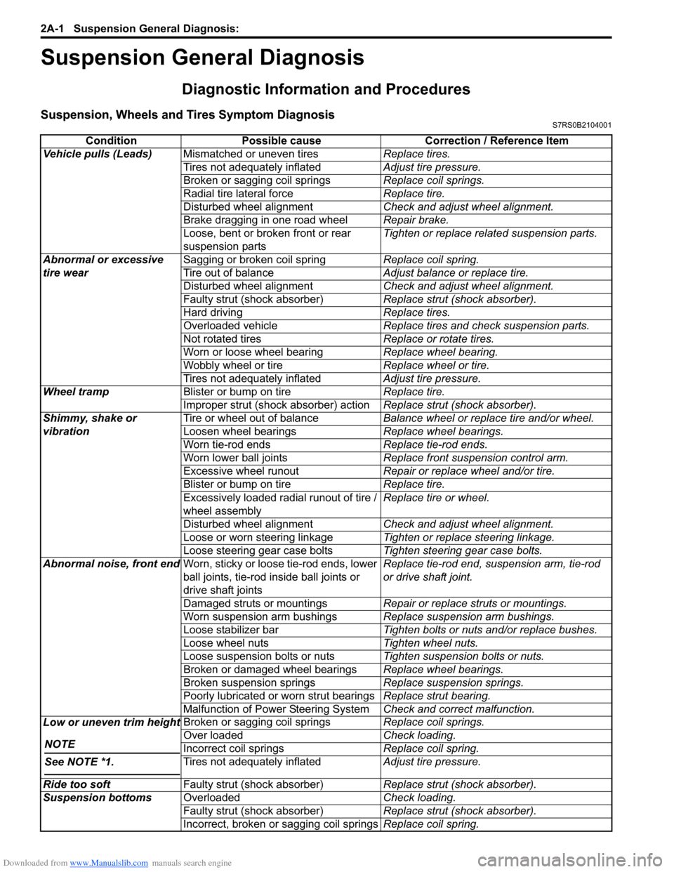
Suspension, Wheels and Tires Symptom DiagnosisS7RS0B2104001
ConditionPossible cause Correction / Reference Item
Vehicle pulls (Leads) Mismatched or uneven tires Replace tires.
Tires not adequately inflated Adjust tire pressure.
Broken or sagging coil springs Replace coil springs.
Radial tire lateral force Replace tire.
Disturbed wheel alignment Check and adjust wheel alignment.
Brake dragging in one road wheel Repair brake.
Loose, bent or broken front or rear
suspension parts Tighten or replace related suspension parts.
Abnormal or excessive
tire wear Sagging or broken coil spring
Replace coil spring.
Tire out of balance Adjust balance or replace tire.
Disturbed wheel alignment Check and adjust wheel alignment.
Faulty strut (shock absorber) Replace strut (shock absorber).
Hard driving Replace tires.
Overloaded vehicle Replace tires and check suspension parts.
Not rotated tires Replace or rotate tires.
Worn or loose wheel bearing Replace wheel bearing.
Wobbly wheel or tire Replace wheel or tire.
Tires not adequately inflated Adjust tire pressure.
Wheel tramp Blister or bump on tire Replace tire.
Improper strut (shock absorber) action Replace strut (shock absorber).
Shimmy, shake or
vibration Tire or wheel out of balance
Balance wheel or replace tire and/or wheel.
Loosen wheel bearings Replace wheel bearings.
Worn tie-rod ends Replace tie-rod ends.
Worn lower ball joints Replace front suspension control arm.
Excessive wheel runout Repair or replace wheel and/or tire.
Blister or bump on tire Replace tire.
Excessively loaded radial runout of tire /
wheel assembly Replace tire or wheel.
Disturbed wheel alignment Check and adjust wheel alignment.
Loose or worn steering linkage Tighten or replace steering linkage.
Loose steering gear case bolts Tighten steering gear case bolts.
Abnormal noise, front end Worn, sticky or loose tie-rod ends, lower
ball joints, tie-rod in side ball joints or
drive shaft joints Replace tie-rod end, su
spension arm, tie-rod
or drive shaft joint.
Damaged struts or mountings Repair or replace struts or mountings.
Worn suspension arm bushings Replace suspension arm bushings.
Loose stabilizer bar Tighten bolts or nuts and/or replace bushes.
Loose wheel nuts Tighten wheel nuts.
Loose suspension bolts or nuts Tighten suspension bolts or nuts.
Broken or damaged wheel bearings Replace wheel bearings.
Broken suspension springs Replace suspension springs.
Poorly lubricated or worn strut bearings Replace strut bearing.
Malfunction of Power Steering System Check and correct malfunction.
Low or uneven trim height
NOTE
See NOTE *1.
Broken or sagging coil springs Replace coil springs.
Over loaded Check loading.
Incorrect coil springs Replace coil spring.
Tires not adequately inflated Adjust tire pressure.
Ride too soft Faulty strut (shock absorber) Replace strut (shock absorber).
Suspension bottoms Overloaded Check loading.
Faulty strut (shock absorber) Replace strut (shock absorber).
Incorrect, broken or sagging coil springs Replace coil spring.
Page 435 of 1496
Downloaded from www.Manualslib.com manuals search engine Front Suspension: 2B-2
Front Wheel Alignment ConstructionS7RS0B2201002
Among factors for front wheel alignment, only toe setting
can be adjusted. Camber and caster are not adjustable.
Therefore, should camber or caster be out of
specification due to the damage caused by hazardous
road conditions or collision, whether the damage is in
body or in suspension should be determined and
damaged body should be repaired or damaged
suspension should be replaced.
Preliminary Checks Prior to Adjustment Front Wheel
Alignment
Steering and vibration complaints are not always the
result of improper wheel alignment. An additional item to
be checked is the possibility of tire lead due to worn or
improperly manufactured tires. “Lead” is the vehicle
deviation from a straight path on a level road without
hand pressure on the steering wheel. Refer to “Radial
Tire Lead / Pull Description in Section 2D” in order to
determine if the vehicle has a tire lead problem. Before
making any adjustment affecting wheel alignment, the
following checks and inspections should be made to
ensure correctness of alignment readings and alignment
adjustments:
• Check all tires for proper inflation pressures and approximately the same tread wear. • Check for loose of ball join
ts. Check tie-rod ends; if
excessive looseness is noted, it must be corrected
before adjusting.
• Check for run-out of wheels and tires.
• Check vehicle trim heights; if it is out of limit and a
correction is needed, it must be done before adjusting
toe.
• Check for loose of suspension control arms.
• Check for loose or missin g stabilizer bar attachments.
• Consideration must be given to excess loads, such as
tool boxes. If this excess load is normally carried in
vehicle, it should remain in vehicle during alignment
checks.
• Consider condition of equipment being used to check alignment and follow manufa cturer’s instructions.
• Regardless of equipment used to check alignment, vehicle must be placed on a level surface.
NOTE
To prevent possible incorrect reading of toe,
camber or caster, vehicle front and rear end
must be moved up and down a few times
before inspection.
Repair Instructions
Front Wheel Alignment Inspection and
Adjustment
S7RS0B2206001
Toe Inspection and Adjustment
Preparation for toe inspection and adjustment.
• Place vehicle in unloaded state on level surface.
• Set steering wheel in straight state.
• Check that inflation pressure of each tire is adjusted properly and wheel is free from deflection.
• Check that each suspension part is free from bend, dent, wear or damage in any other form.
• Check that ground clearance at the right and left is just about the same.
Inspection
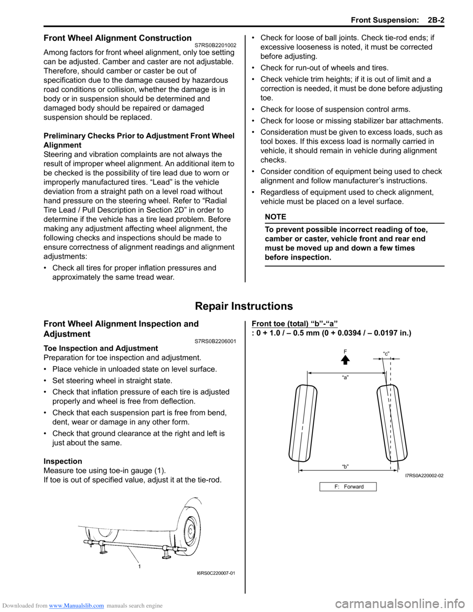
Measure toe using toe-in gauge (1).
If toe is out of specified value, adjust it at the tie-rod. Front toe (total) “b”-“a”
: 0 + 1.0 / – 0.5 mm (0 + 0.0394 / – 0.0197 in.)
I6RS0C220007-01
F: Forward
“a”
“c”
“b” F
I7RS0A220002-02
Page 448 of 1496
Downloaded from www.Manualslib.com manuals search engine 2B-15 Front Suspension:
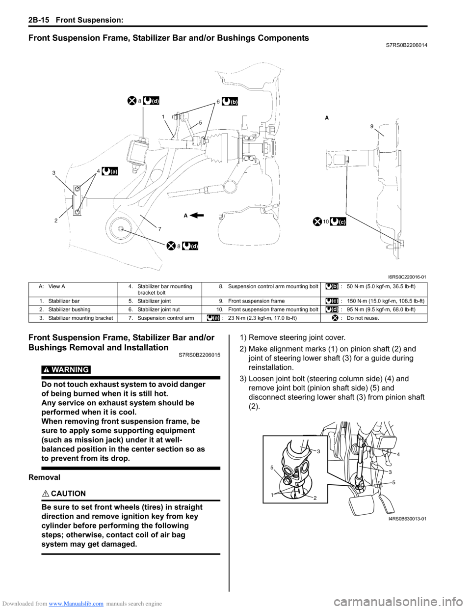
Front Suspension Frame, Stabilizer Bar and/or Bushings ComponentsS7RS0B2206014
Front Suspension Frame, Stabilizer Bar and/or
Bushings Removal and Installation
S7RS0B2206015
WARNING!
Do not touch exhaust system to avoid danger
of being burned when it is still hot.
Any service on exhaust system should be
performed when it is cool.
When removing front suspension frame, be
sure to apply some supporting equipment
(such as mission jack) under it at well-
balanced position in the center section so as
to prevent from its drop.
Removal
CAUTION!
Be sure to set front wheels (tires) in straight
direction and remove ignition key from key
cylinder before performing the following
steps; otherwise, contact coil of air bag
system may get damaged.
1) Remove steering joint cover.
2) Make alignment marks (1) on pinion shaft (2) and joint of steering lower shaft (3) for a guide during
reinstallation.
3) Loosen joint bolt (steering column side) (4) and remove joint bolt (pin ion shaft side) (5) and
disconnect steering lower shaft (3) from pinion shaft
(2).
I6RS0C220016-01
A: View A 4. Stabilizer bar mounting
bracket bolt 8. Suspension control arm mounting bolt : 50 N
⋅m (5.0 kgf-m, 36.5 lb-ft)
1. Stabilizer bar 5. Stabilizer joint 9. Front suspension frame : 150 N⋅m (15.0 kgf-m, 108.5 lb-ft)
2. Stabilizer bushing 6. Stabilizer joint nut10. Front suspension frame mounting bolt : 95 N ⋅m (9.5 kgf-m, 68.0 lb-ft)
3. Stabilizer mounting bracket 7. Suspension control arm : 23 N⋅m (2.3 kgf-m, 17.0 lb-ft) : Do not reuse.
5
2
1
5
34
3
I4RS0B630013-01
Page 449 of 1496
Downloaded from www.Manualslib.com manuals search engine Front Suspension: 2B-16
4) Hoist vehicle and remove both wheels referring to “Wheel Removal and Installation in Section 2D”.
5) Remove cotter pins and tie-rod end nuts, and then disconnect both tie-rod ends from steering knuckles
referring to “Tie-Rod End Re moval and Installation in
Section 6C”.
6) Disconnect couplers of torque sensor and P/S motor.
7) Remove suspension control arm referring to “Suspension Control Arm / Bushing Removal and
Installation”.
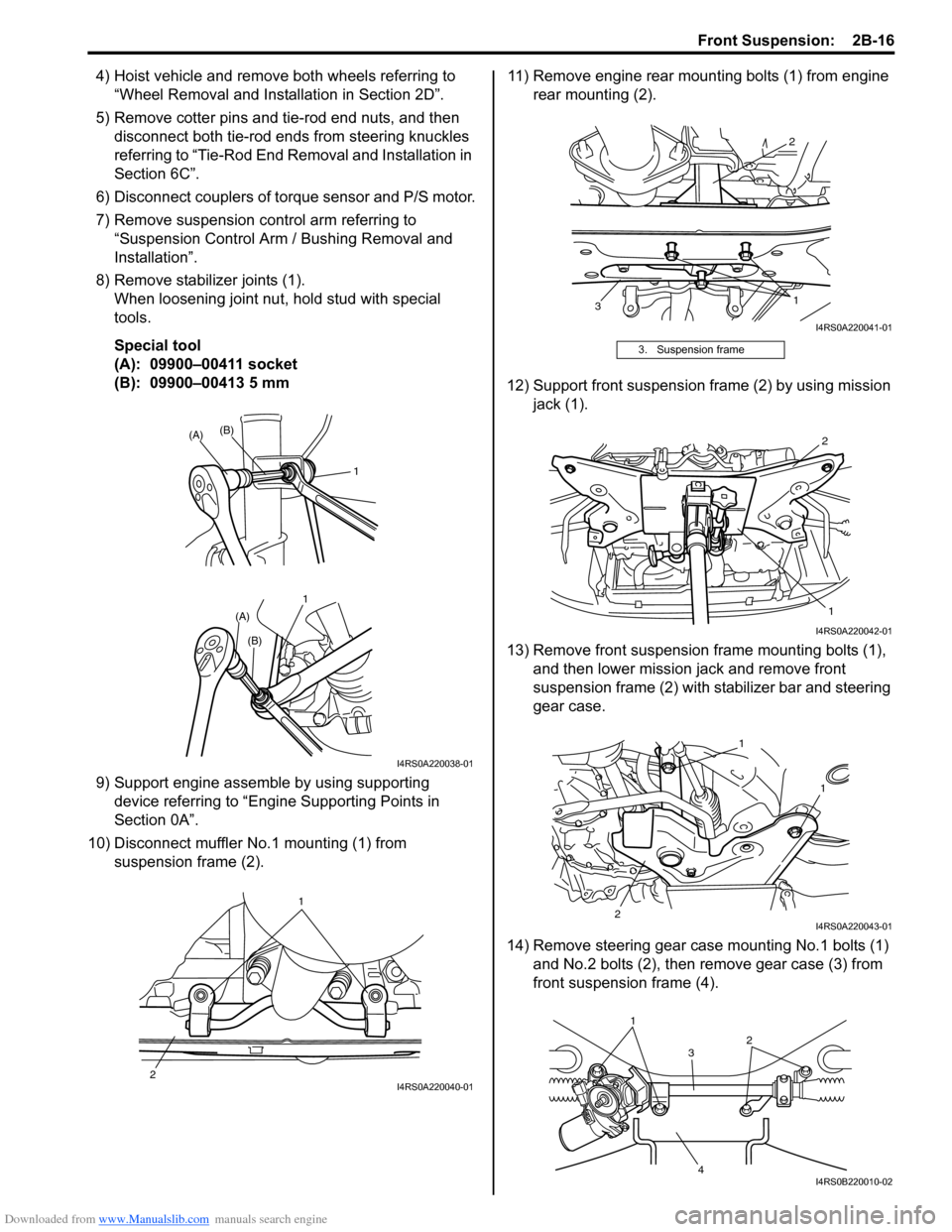
8) Remove stabilizer joints (1). When loosening joint nu t, hold stud with special
tools.
Special tool
(A): 09900–00411 socket
(B): 09900–00413 5 mm
9) Support engine assemble by using supporting device referring to “Engine Supporting Points in
Section 0A”.
10) Disconnect muffler No.1 mounting (1) from suspension frame (2). 11) Remove engine rear mounting bolts (1) from engine
rear mounting (2).
12) Support front suspension frame (2) by using mission jack (1).
13) Remove front suspension frame mounting bolts (1), and then lower mission jack and remove front
suspension frame (2) with st abilizer bar and steering
gear case.
14) Remove steering gear case mounting No.1 bolts (1) and No.2 bolts (2), then remove gear case (3) from
front suspensio n frame (4).
11
(A)
(A)
(B)
(B)
I4RS0A220038-01
1
2
I4RS0A220040-01
3. Suspension frame
2
3 1
I4RS0A220041-01
2
1
I4RS0A220042-01
1
2 1
I4RS0A220043-01
1
3
4 2
I4RS0B220010-02